
Microstructure Effect of Heat Input on Ballistic Performance of Welded High Strength Armor Steel

 , ,
, ,  and
and
Abstract
:1. Introduction
2. Materials and Methods
2.1. Materials
2.2. Welding Process
2.3. Metallographic and Microstructure Analysis
2.4. Microhardness Measurements
2.5. Charpy Impact
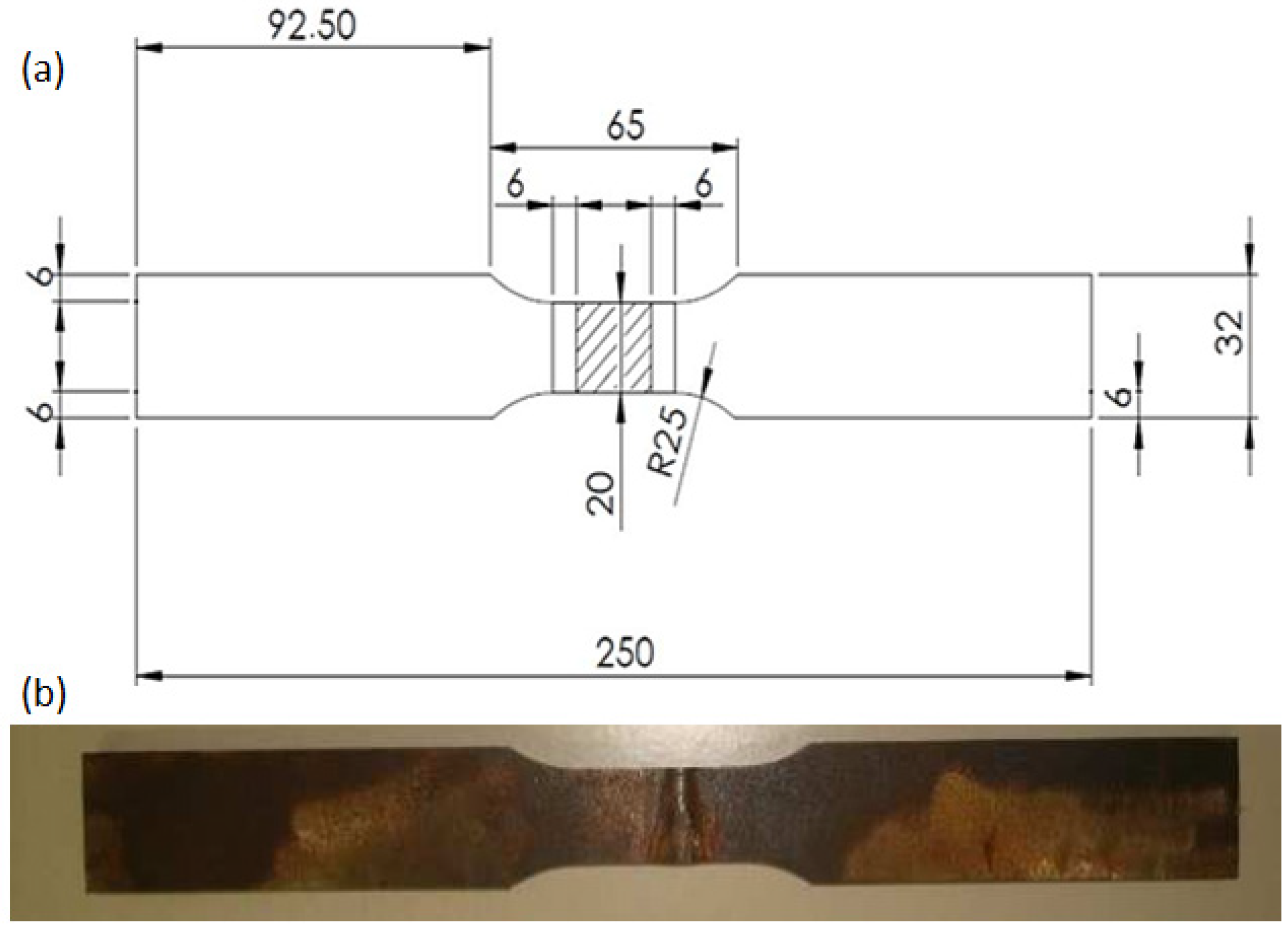
2.6. Tensile Test
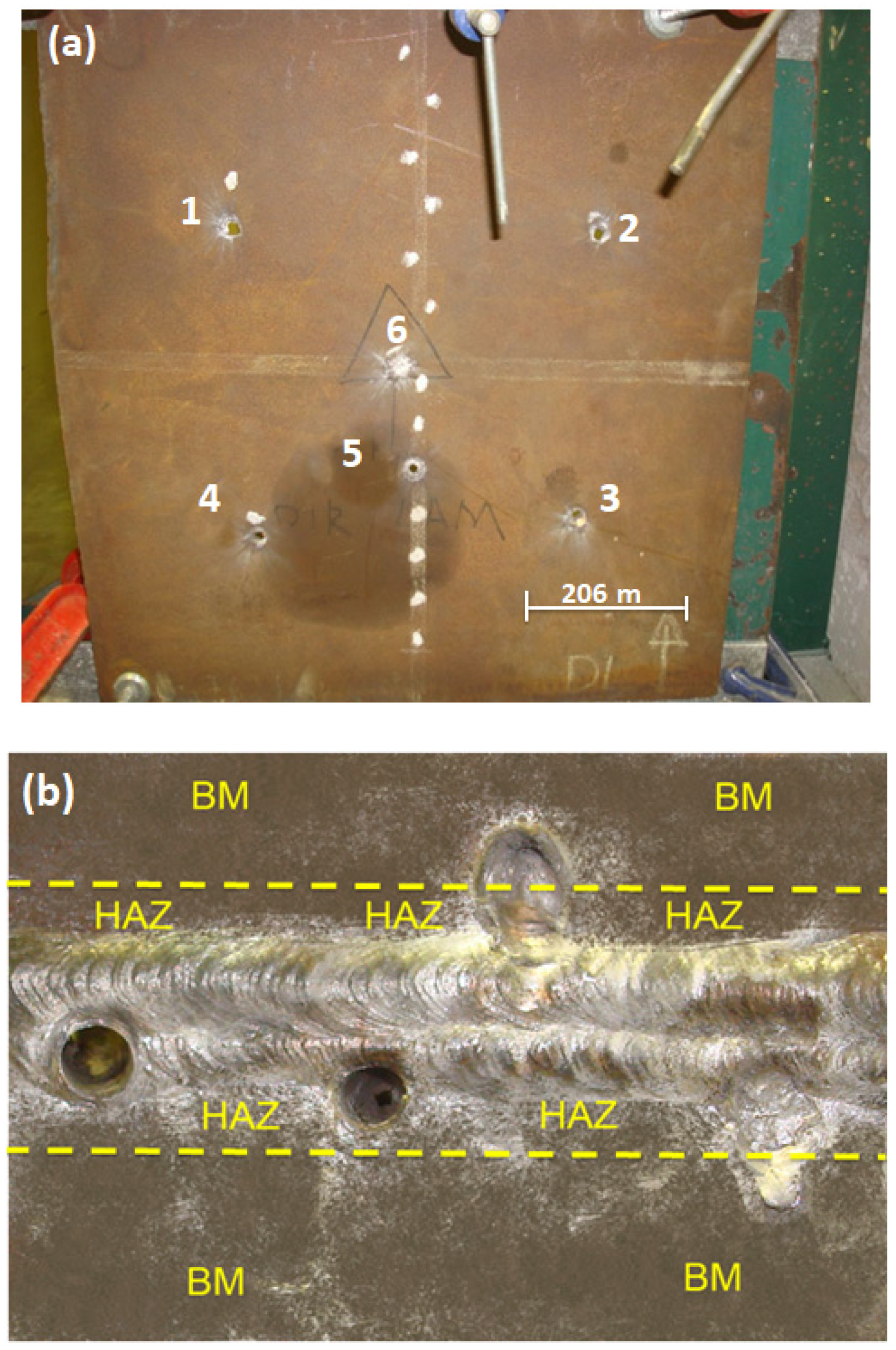
2.7. Ballistic Testing
3. Results and Discussion
3.1. Characterization of Base Metal Steel
3.2. Metallographic Analysis
3.3. Vickers Microhardness Profile
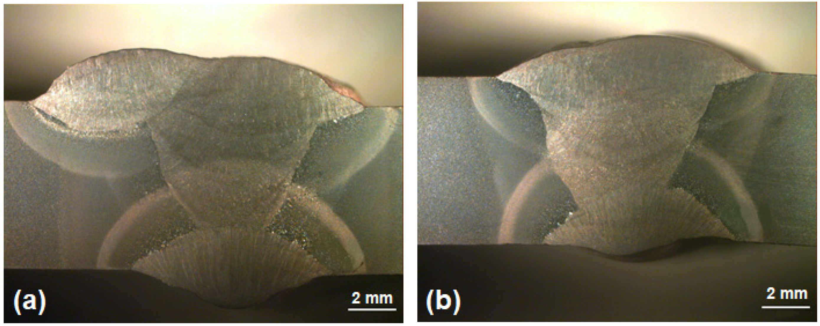
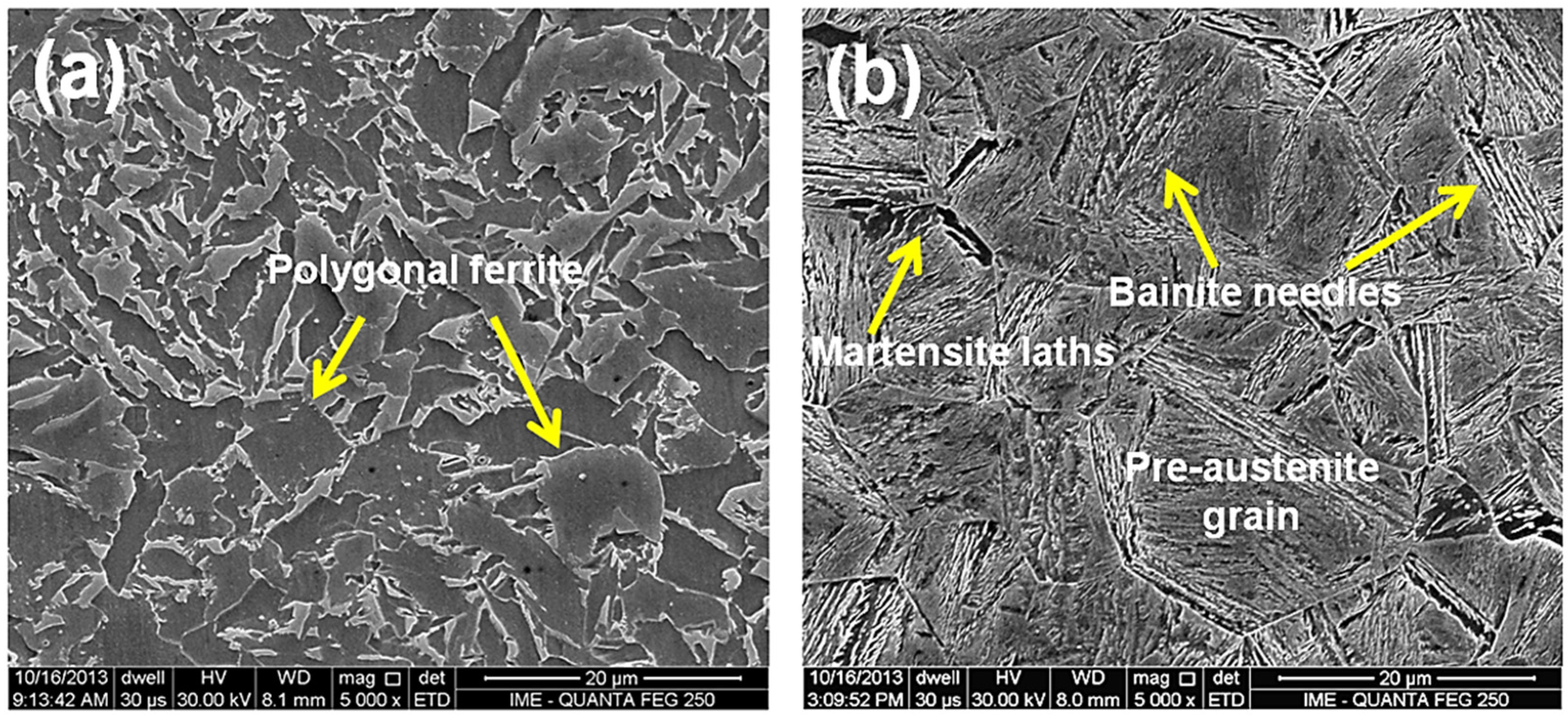
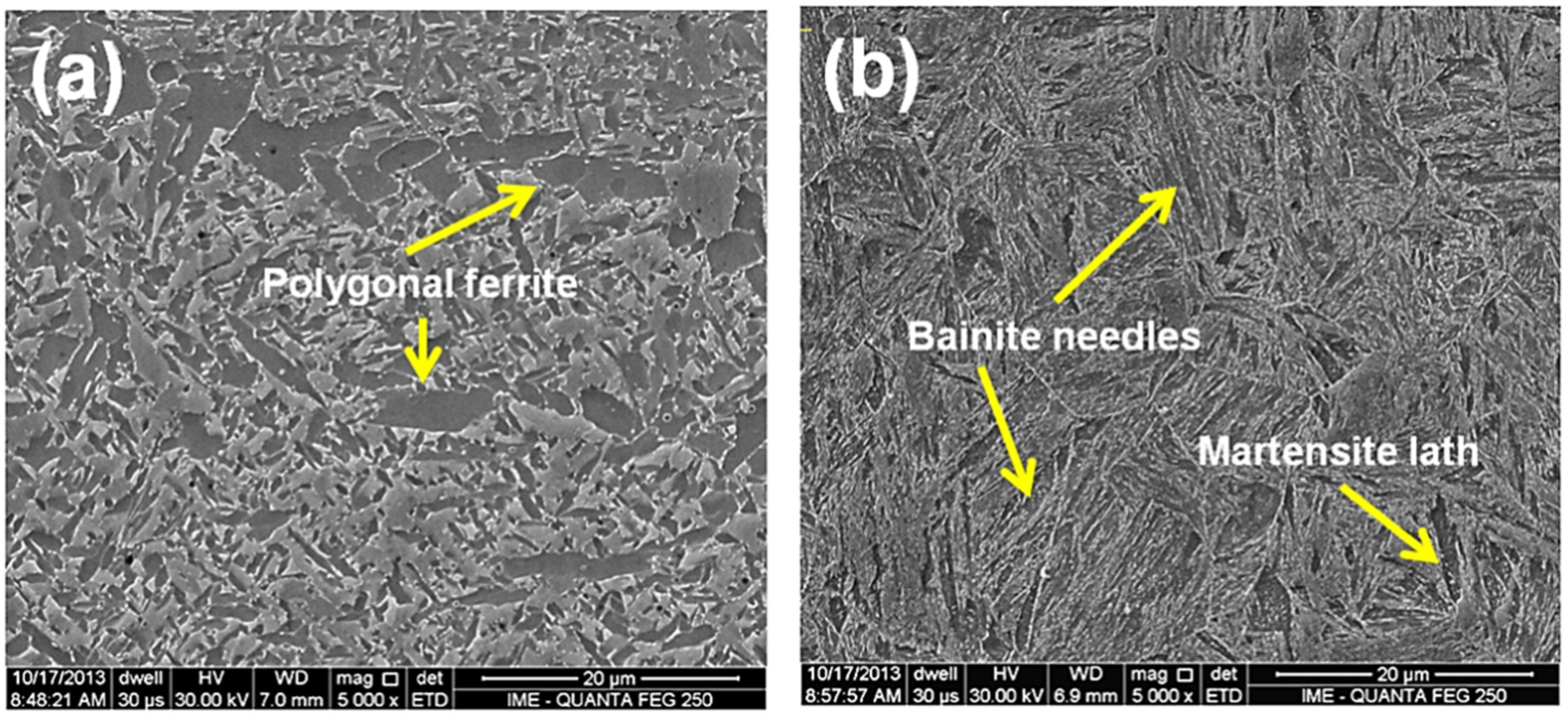
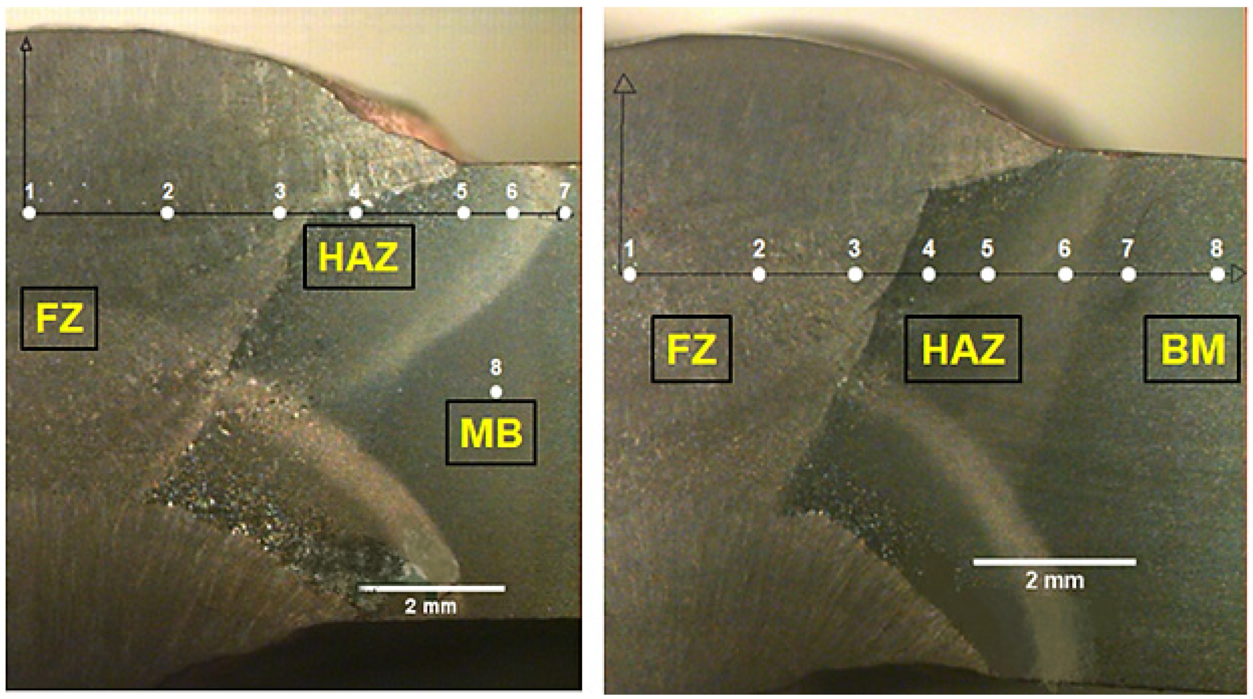
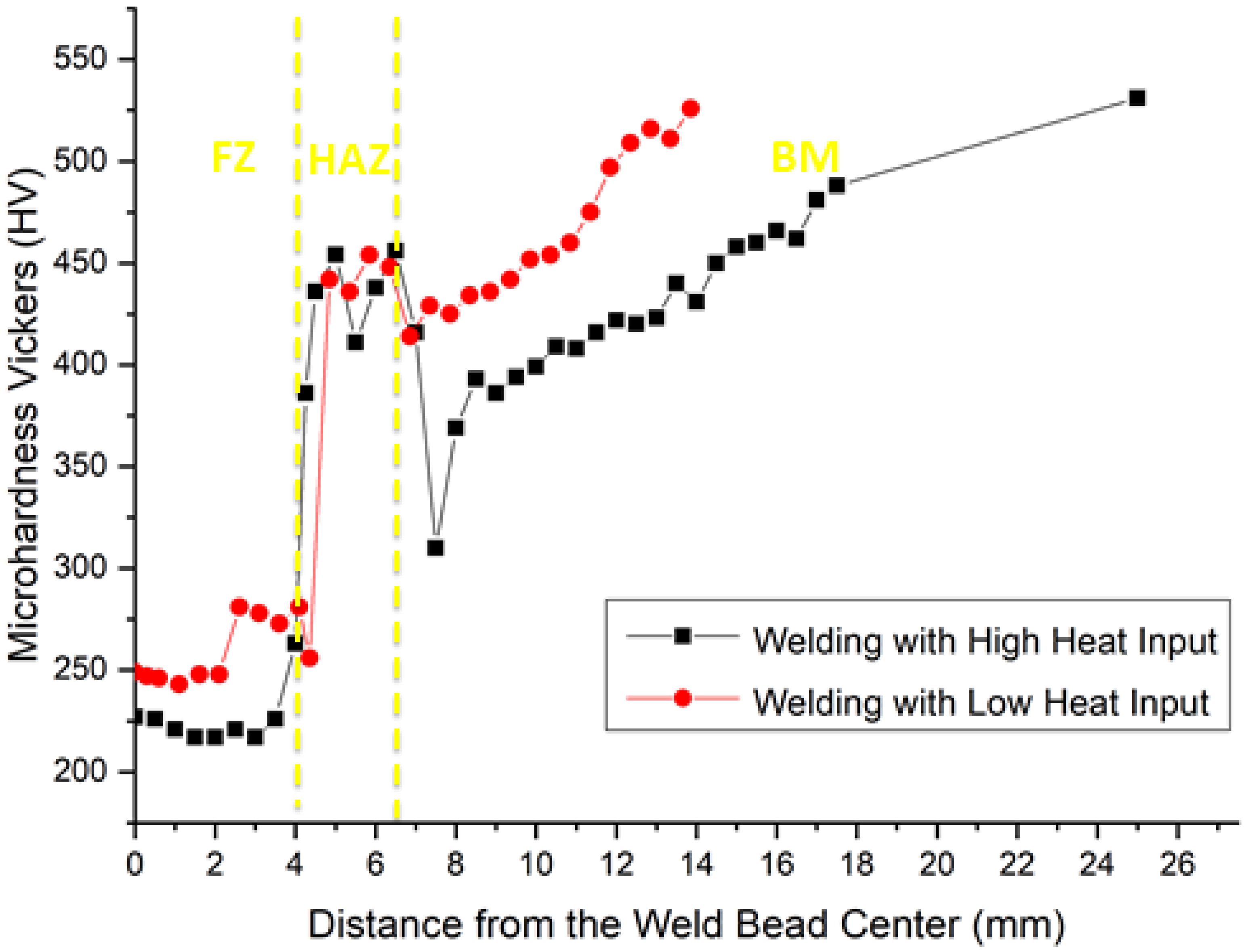
- 1st and 2nd region: with low microhardness, associated with the FZ only, where the filler metal is predominant. This region has a ductile microstructure of polygonal ferrite (219–259 HV). However, the grain size resulting from the LHI condition is smaller than that related to the HHI condition in Figure 9a and Figure 10a. Most possibly the increase in heat input contributes to growing the grains. This might be the reason why the HHI has promoted a decrease in hardness, as reported by Reddy and Mohandas [16] as well as Savic and Cabrilo [25].
- 3rd region: located close to the FZ/HAZ interface with comparatively higher hardness as a result of either coarse or thin martensite (384–275 HV). The coarse martensite was developed due to the HHI condition, Figure 9b, while thin martensite can be seen for the LHI condition in Figure 10b. For the HHI microstructure in Figure 9b, it is also possible to identify bainite needles. Generally, a microstructure composed of these bainite needles presents higher toughness [17]. However, due to the small fraction, it did not show much difference in hardness. As for the LHI condition, Figure 10b, bainite needles apparently predominate.
- 4th region in the HAZ, located close to the HAZ/FZ interface, with a sensible increase in hardness (349–430 HV), in which grows the presence of bainite needles within acicular martensite.
- 6th region: known as partial transformation zone located at the end of the HAZ, close to the HAZ/BM interface, showing a minor decrease in microhardness due to the presence of ferrite together with martensite, and bainite 424–429 HV);
- 7th region: identified as the BM close to the BM/HAZ interface, discloses a continuous increase in microhardness (437–446 HV) due to the lower temperatures reached in this region. It presents the same microstructure as the 6th region but with predominance of tempered martensite as well as lower percentage of bainite and ferrite.
- 8th region: corresponding to the BM only, with the highest hardness (481–503 HV) associated with tempered martensite with both acicular and lath types, Figure 8.
3.4. Charpy Impact Energy
3.5. Tensile Strength
3.6. Ballistic Results
3.7. Ballistic Damage Mode
4. Conclusions
- The ballistic limit performance of the welded joint of a quenched and tempered (Q&T) high strength armor (HHA) steel was for the first time evaluated by the V50 standard method using high impact velocity 7.62 mm caliber ammunition.
- Based on two welding heat inputs; lower, 0.8 kJ/mm (LHI) and higher, 1.2 kJ/mm (HHI), selected from the literature, the effect of heat input on the hardness, considered a major ballistic requirement, was disclosed together with V50 for the Q&T HHA steel welded joint region.
- Quantitative results of microhardness and V50 limit velocity for the fusion zone (FZ), heat-affected zone (HAZ) and base metal (BM) revealed that, in spite of BM being the hardest region with 503 HV, the HAZ is ballistically the most resistant, with V50 = 668 m/s, associated with LHI.
- The unexpected finding that HAZ with lower hardness might be more ballistic resistant than BM is now revealed in terms of developed microstructure after the LHI welding procedure. While the BM owns its higher hardness to Q&T martensite, unaffected by the welding temperature, the HAZ displays a V50 ballistic tougher microstructure due to predominant formation of bainite, which causes a superior ballistic performance.
- Ballistic damage modes of HHI and LHI weldments disclosed evidence of plugging, petaling, and fragmentation associated with a combination of ductile and brittle projectile perforation. A market degree of fragmentation in the LHI distal face of FZ, HAZ, and BM indicates predominant brittle mode, which correlates with measured higher hardness and impact toughness.
Author Contributions
Funding
Institutional Review Board Statement
Informed Consent Statement
Data Availability Statement
Acknowledgments
Conflicts of Interest
References
- Jena, P.; Mishra, B.; RameshBabu, M.; Babu, A.; Singh, A.; SivaKumar, K.; Bhat, T.B. Effect of heat treatment on mechanical and ballistic properties of a high strength armour steel. Int. J. Impact Eng. 2010, 37, 242–249. [Google Scholar] [CrossRef]
- Vasconcelos, C.H.M.; Loayza, C.R.L.; Assunção, P.D.C.; Junior, F.F.B.; Baia, P.E.C.; Borges, D.J.A.; Braga, E.M. High-hardness armor welded by CW-GMAW: Economic, geometric and CGHAZ analysis. J. Braz. Soc. Mech. Sci. Eng. 2019, 41, 268. [Google Scholar] [CrossRef]
- Jo, M.C.; Kim, S.; Suh, D.W.; Hong, S.S.; Kim, H.K.; Sohn, S.S.; Lee, S. Effect of tempering conditions on adiabatic shear banding during dynamic compression and ballistic impact tests of ultra-high-strength armor steel. Mater. Sci. Eng. A 2020, 792, 139818. [Google Scholar] [CrossRef]
- Popławski, A.; Kędzierski, P.; Morka, A. Identification of Armox 500T steel failure properties in the modeling of perforation problems. Mater. Des. 2020, 190, 108536. [Google Scholar] [CrossRef]
- Magudeeswaran, G.; Balasubramanian, V.; Reddy, G.M. Metallurgical characteristics of armour steel welded joints used for combat vehicle construction. Def. Technol. 2018, 14, 590–606. [Google Scholar] [CrossRef]
- Yurianto, Y.; Pratikto, P.; Soenoko, R.; Suprapto, W. Effect of quench and temper on hardness and wear of HRP steel (armor steel candidate). Eastern-Eur. J. Enterp. Technol. 2019, 3, 55–61. (In Russian) [Google Scholar] [CrossRef]
- Ma, B.-H.; Ma, D.-F.; Wang, H.-R.; Chen, D.-N.; Zhou, F.-H. Ballistic impact response of resistance-spot-welded (RSW) double-layered plates for Q&P980 steel. Def. Technol. 2021. [Google Scholar] [CrossRef]
- Oliveira, S.D.S.; Weber, R.P.; Paula, A.D.S.; Monteiro, S.N. The Influence of the Microstructure of an HHA Steel on the Formation of Adiabatic Shear Bands, after High Deformation Rates. Mater. Sci. Forum 2020, 1012, 366–371. [Google Scholar] [CrossRef]
- Saxena, A.; Kumaraswamy, A.; Dwivedi, S.P.; Srivastava, A.K.; Maurya, N.K. Experimental and computational investigation on dynamic fracture toughness (J) behavior of multi-pass SMA armor steel weldments. Theor. Appl. Fract. Mech. 2020, 106, 102502. [Google Scholar] [CrossRef]
- Fan, X.; Li, Y.; Qi, Y.; Cai, X.; Wang, Z.; Ma, C. Mechanical properties of cryogenic high manganese steel joints filled with nickel-based materials by SMAW and SAW. Mater. Lett. 2021, 304, 130596. [Google Scholar] [CrossRef]
- Cabrilo, A.; Geric, K. Weldability of High Hardness Armor Steel. Adv. Mater. Res. 2016, 1138, 79–84. [Google Scholar] [CrossRef]
- Cabrilo, A.; Sedmak, A.; Burzic, Z.; Perkovic, S. Fracture mechanics and fatigue crack propagation in armor steel welds. Eng. Fail. Anal. 2019, 106, 104155. [Google Scholar] [CrossRef]
- Bunaziv, I.; Wenner, S.; Ren, X.; Frostevarg, J.; Kaplan, A.F.; Akselsen, O.M. Filler metal distribution and processing stability in laser-arc hybrid welding of thick HSLA steel. J. Manuf. Process. 2020, 54, 228–239. [Google Scholar] [CrossRef]
- Wilson, I. The Development of Welding Techniques for British Fighting Vehicles; Crown Copyright: London, UK, 1987; pp. 47–55. [Google Scholar]
- Ade, F. Ballistic qualification of armour steel weldments. Weld. J. 1991, 70, 53–54. [Google Scholar]
- Reddy, G.M.; Mohandas, T. Ballistic performance of high-strengh low-alloy steel weldments. J. Mater. Process. Technol. 1996, 57, 23–30. [Google Scholar] [CrossRef]
- Crouch, I.G. Metallic armour, from cast aluminium alloys to high strength steels. Mater. Forum 1988, 12, 31–37. [Google Scholar]
- Ramana, P.V.; Reddy, G.M.; Mohandas, T. Residual stress distribution in high strength low alloy steel weldments. Ind. J. Non Dest. Test Eval. 2007, 6, 33–40. [Google Scholar]
- Pramanick, A.; Das, H.; Reddy, G.; Ghosh, M.; Das, G.; Nandy, S.; Pal, T. Development and design of microstructure based coated electrode for ballistic performance of shielded metal arc welded armour steel joints. Mater. Des. 2016, 103, 52–62. [Google Scholar] [CrossRef]
- Reddy, G.M.; Mohandas, T.; Papukutty, K. Effect of welding process on the ballistic performance of high-strength low-alloy steel weldments. J. Mater. Process. Technol. 1998, 74, 27–35. [Google Scholar] [CrossRef]
- Reddy, G.M.; Mohandas, T.; Sarma, D.S. Cold cracking studies on low alloy steel weldments: Effect of filler metal composition. Sci. Technol. Weld. Join. 2003, 8, 407–414. [Google Scholar] [CrossRef]
- Saxena, A.; Kumaraswamy, A.; Reddy, G.M.; Madhu, V. Influence of welding consumables on tensile and impact properties of multi-pass SMAW Armox 500T steel joints vis-a-vis base metal. Def. Technol. 2018, 14, 188–195. [Google Scholar] [CrossRef]
- Balakrishnan, M.; Balasubramanian, V.; Reddy, G.M. Effect of joint design on ballistic performance of quenched and tempered steel welded joints. Mater. Des. 2014, 54, 616–623. [Google Scholar] [CrossRef]
- Balakrishnan, M.; Balasubramanian, V.; Reddy, G.M.; Sivakumar, K. Effect of buttering and hardfacing on ballistic performance of shielded metal arc welded armour steel joints. Mater. Des. 2011, 32, 469–479. [Google Scholar] [CrossRef]
- Savic, B.; Cabrilo, A. Effect of Heat Input on the Ballistic Performance of Armor Steel Weldments. Materials 2021, 14, 3617. [Google Scholar] [CrossRef]
- US Army. MIL-DTL-46100E (MR). Amendment 1. Detail Specification. Armor Plate, Steel, Wrought, High-Hardness. 2008. Available online: http://everyspec.com/MIL-SPECS/MIL-SPECS-MIL-DTL/MIL-DTL-46100E_AMENDMENT-1_20496/ (accessed on 7 September 2021).
- US Army. MIL-STD-662F Department of Defense. 1997. Available online: http://everyspec.com/MIL-STD/MIL-STD-0500-0699/MIL-STD-662F_6718/ (accessed on 7 September 2021).
- American Society for Testing and Materials. Standard Test Method for Knoop and Vickers Hardness of Materials, ASTM E384-11. 2011. Available online: https://compass.astm.org/document/?contentCode=ASTM%7CE0384-11%7Cen-US (accessed on 6 September 2021).
- American Society for Testing and Materials. Standard Test Methods for Notched Bar Impact Testing of Metallic Materials, ASTM, E23-1a. 2002. Available online: https://compass.astm.org/document/?contentCode=ASTM%7CE0023-01A%7Cen-US (accessed on 7 September 2021).
- American Society for Testing and Materials. Standard Test Methods and Definitions for Mechanical Testing of Steel Products, ASTM A370-14. 2014. Available online: https://compass.astm.org/document/?contentCode=ASTM%7CA0370-14%7Cen-US (accessed on 7 September 2021).
- United States Department of the Army. Test Operations Procedure 2-2-710. Ballistic Tests of Armor Materials. 1984. Available online: https://www.document-center.com/standards/show/TOP-2-2-710 (accessed on 7 September 2021).
- Oliveira, M.S.; da Luz, F.S.; Lopera, H.A.C.; Nascimento, L.F.C.; Filho, F.D.C.G.; Monteiro, S.N. Energy Absorption and Limit Velocity of Epoxy Composites Incorporated with Fique Fabric as Ballistic Armor—A Brief Report. Polymers 2021, 13, 2727. [Google Scholar] [CrossRef]
- Unfried, J.S.; Garzon, C.M.; Giraldo, J.E. Numerical and experimental analysis of microstructure evolution during arc welding in armor plate steels. J. Mater. Process. Technol. 2009, 209, 1688–1700. [Google Scholar] [CrossRef]
- Cabrilo, A.; Geric, K. Fracture mechanic and charpy impact properties of a crack in weld metal, HAZ and base metal of welded armor steel. Procedia Struct. Integr. 2018, 13, 2059–2064. [Google Scholar] [CrossRef]
- Frómeta, D.; Parareda, S.; Lara, A.; Molas, S.; Casellas, D.; Jonsén, P.; Calvo, J. Identification of fracture toughness parameters to understand the fracture resistance of advanced high strength sheet steels. Eng. Fract. Mech. 2020, 229, 106949. [Google Scholar] [CrossRef]
- Li, Q.Q.; Li, E.; Chen, T.; Wu, L.; Wang, G.; He, Z. Improve the frontal crashworthiness of vehicle through the design of front rail. Thin-Walled Struct. 2021, 162, 107588. [Google Scholar] [CrossRef]


| Elem | C | Mn | Si | Ni | Cr | Mo | Cu | Ti | P + S |
|---|---|---|---|---|---|---|---|---|---|
| % | 0.31 | 0.42 | 0.93 | 0.57 | 0.76 | 0.30 | 0.05 | 0.03 | 0.009 |
| Weldment | Region | High Heat Input (HV) | Low Heat Input (HV) |
|---|---|---|---|
| FZ only | 1 | 222 ± 4.9 | 246 ± 2.5 |
| 2 | 219 ± 2.8 | 259 ± 19.0 | |
| FZ near HAZ | 3 | 384 ± 86.1 | 275 ± 3.5 |
| HAZ near FZ | 4 | 430 ± 20.3 | 349 ± 131.5 |
| HAZ only | 5 | 375 ± 33.6 | 445 ± 12.7 |
| HAZ near BM | 6 | 414 ± 6.5 | 429 ± 14.2 |
| BM near HAZ | 7 | 437 ± 13.8 | 446 ± 10.5 |
| BM only | 8 | 481 ± 26.8 | 24.3 |
| Notched Specimen Location | Absorbed Energy (J) |
|---|---|
| Base Metal Longitudinal | 28 ± 3 |
| Base Metal Transversal | 29 ± 2 |
| Weldment HHI | 53 ± 3 |
| Weldment LHI | 69 ± 2 |
| Tensile Property | BM | HHI | LHI |
|---|---|---|---|
| Ultimate Stress (MPa) | 1834 ± 58 | 928 ± 16 | 992 ± 60 |
| Related toughness (103 kJ/m3) | 117 ± 4 | 82 ± 2 | 91 ± 5 |
| Heat Input | Shooting | V50 Limit Velocity (m/s) | Ei absorbed Impact Energy (kJ) | ||||||
|---|---|---|---|---|---|---|---|---|---|
| Region | |||||||||
| Without heat input | Base Metal | 579 (T) | 565 (P) | 1.61 | 1.53 | ||||
| 557 (P) | 581 (T) | 1.49 | 1.62 | ||||||
| 552 (P) | 568 (T) | 1.46 | 1.55 | ||||||
| V50 = 567 | Ei = 1.54 ± 0.06 | ||||||||
| High heat input | FZ | 529 (P) | 536 (T) | 530 (P) | 1.34 | 1.38 | 1.35 | ||
| 531 (P) | 538 (T) | 546 (T) | 1.35 | 1.39 | 1.43 | ||||
| 533 (T) | 508 (P) | 1.36 | 1.24 | ||||||
| 528 (P) | 541 (T) | 1.34 | 1.40 | ||||||
| V50 = 532 | Ei = 1.36 ± 0.05 | ||||||||
| HAZ | 607 (P) | 609 (P) | 1.77 | 1.78 | |||||
| 611 (P) | 634 (T) | 1.79 | 1.93 | ||||||
| 641 (T) | 620 (P) | 1.97 | 1.85 | ||||||
| 628 (T) | 626 (T) | 1.89 | 1.88 | ||||||
| V50 = 622 | Ei = 1.85 ± 0.07 | ||||||||
| Low heat input | FZ | 543 (P) | 553 (P) | 546 (P) | 1.42 | 1.47 | 1.43 | ||
| 557 (T) | 547 (P) | 560 (T) | 1.49 | 1.44 | 1.51 | ||||
| 570 (T) | 558 (T) | 1.56 | 1.49 | ||||||
| 582 (T) | 544 (P) | 1.63 | 1.42 | ||||||
| V50 = 556 | Ei = 1.50 ± 0.06 | ||||||||
| HAZ | 684 (T) | 650 (P) | 2.25 | 2.03 | |||||
| 669 (T) | 674 (T) | 2.15 | 2.18 | ||||||
| 663 (P) | 672 (T) | 2.11 | 2.17 | ||||||
| 665 (P) | 667 (P) | 2.12 | 2.14 | ||||||
| V50 = 668 | Ei = 2.14 ± 0.06 | ||||||||
Publisher’s Note: MDPI stays neutral with regard to jurisdictional claims in published maps and institutional affiliations. |
© 2021 by the authors. Licensee MDPI, Basel, Switzerland. This article is an open access article distributed under the terms and conditions of the Creative Commons Attribution (CC BY) license (https://creativecommons.org/licenses/by/4.0/).
Share and Cite
Souza, E.R.S.; Weber, R.P.; Monteiro, S.N.; Oliveira, S.d.S. Microstructure Effect of Heat Input on Ballistic Performance of Welded High Strength Armor Steel. Materials 2021, 14, 5789. https://doi.org/10.3390/ma14195789
Souza ERS, Weber RP, Monteiro SN, Oliveira SdS. Microstructure Effect of Heat Input on Ballistic Performance of Welded High Strength Armor Steel. Materials. 2021; 14(19):5789. https://doi.org/10.3390/ma14195789
Chicago/Turabian StyleSouza, Elson Renato Santos, Ricardo Pondé Weber, Sergio Neves Monteiro, and Suzane de Sant’Ana Oliveira. 2021. "Microstructure Effect of Heat Input on Ballistic Performance of Welded High Strength Armor Steel" Materials 14, no. 19: 5789. https://doi.org/10.3390/ma14195789
APA StyleSouza, E. R. S., Weber, R. P., Monteiro, S. N., & Oliveira, S. d. S. (2021). Microstructure Effect of Heat Input on Ballistic Performance of Welded High Strength Armor Steel. Materials, 14(19), 5789. https://doi.org/10.3390/ma14195789