
Microstructure and Wear Property of ZrO2-Added NiCrAlY Prepared by Ultrasonic-Assisted Direct Laser Deposition

 ,
, 
Abstract
:1. Introduction
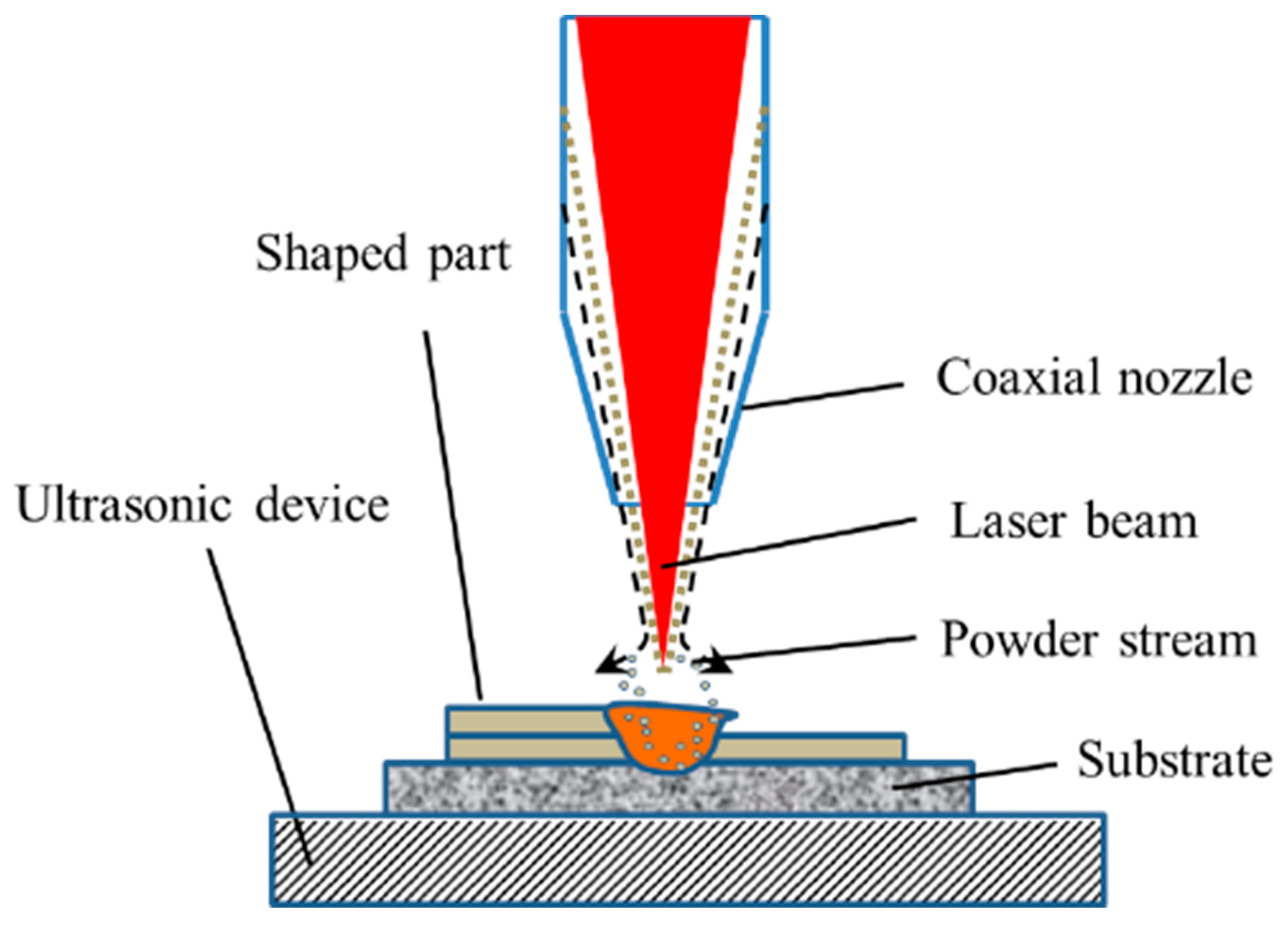
2. Experimental Procedures
3. Results and Discussion
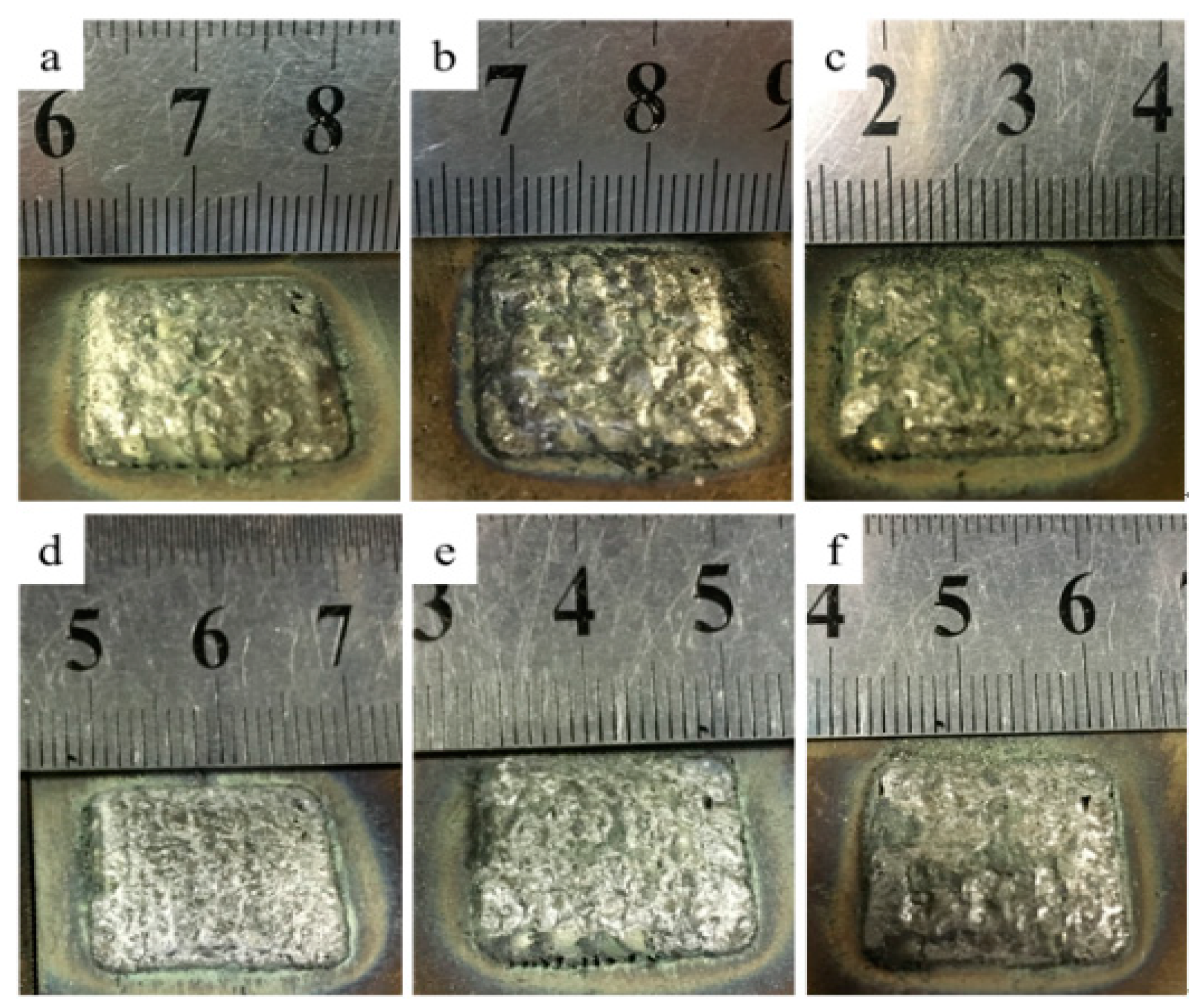
3.1. Macroscopic Morphology
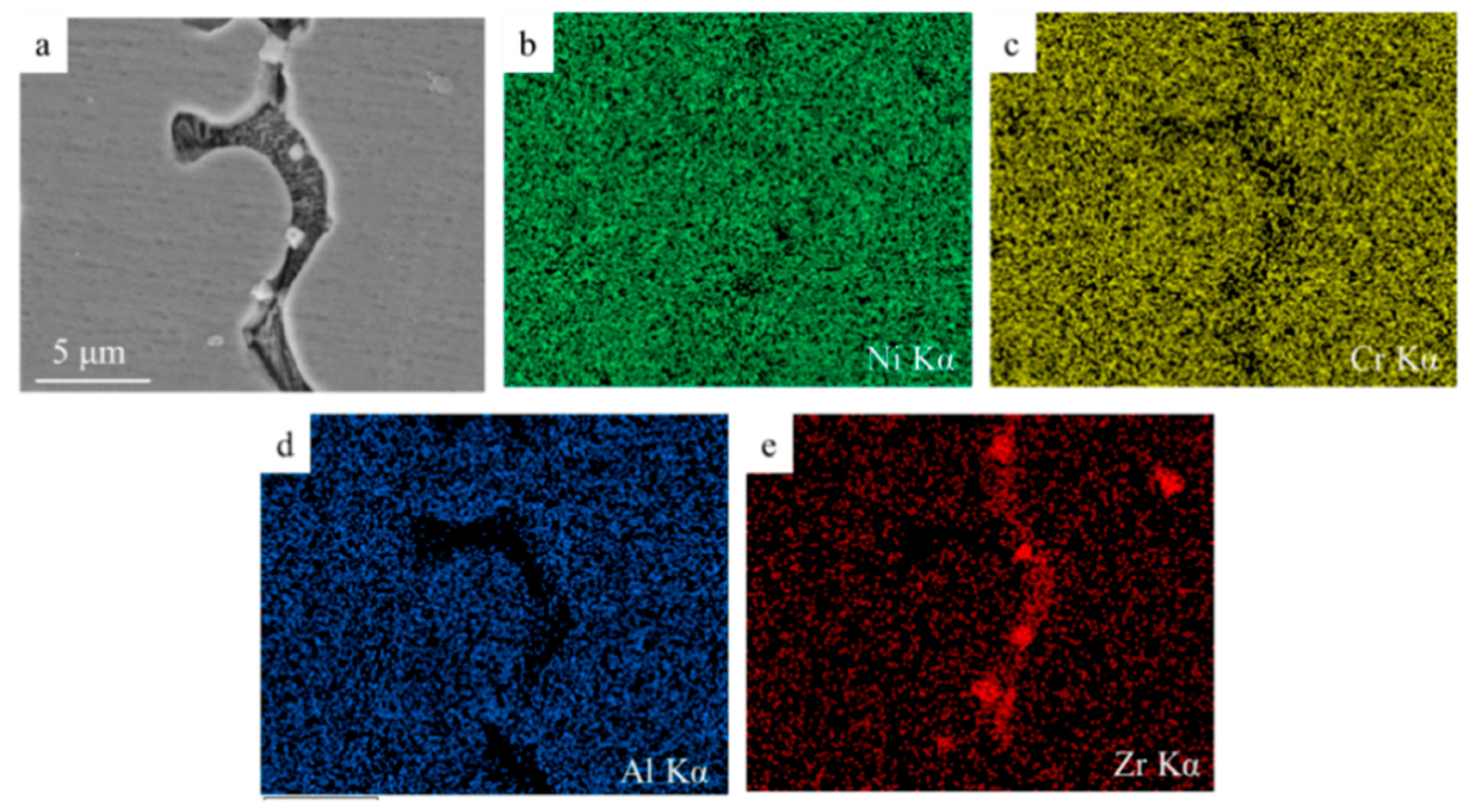
3.2. Oxide Islands
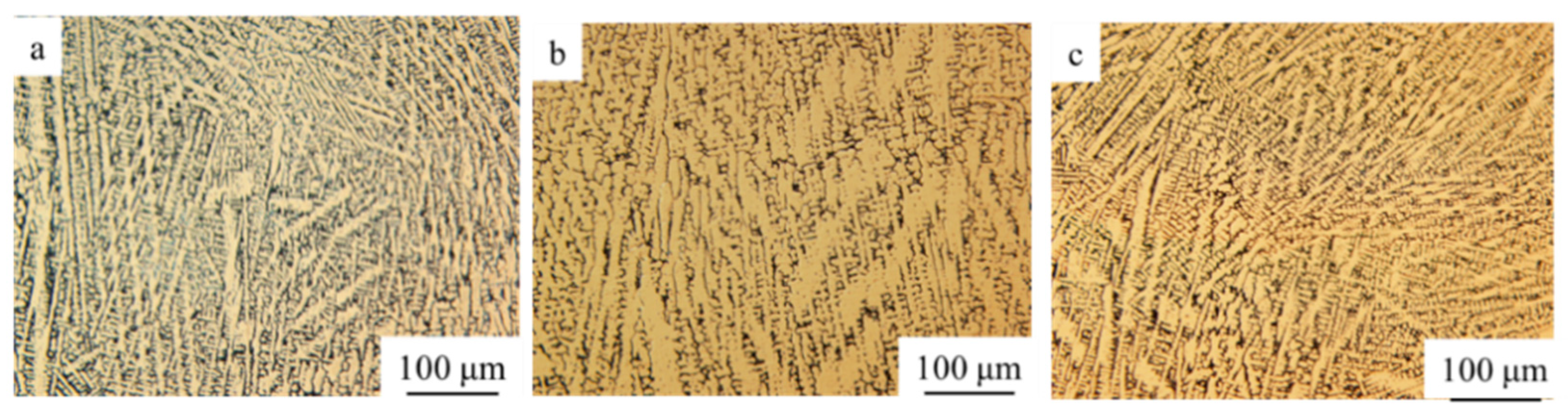
3.3. Microstructure
3.4. Phase Patterns
3.5. Mechanical Properties
4. Conclusions
- Ultrasonic-assisted could make the upper surface smoother and flatter. Ultrasonic sound flow, cavitation and other effects on the molten pool could effectively reduce or remove the ceramic oxide islands in the matrix, further to improve the microstructural homogeneity of the ZrO2-added NiCrAlY;
- The microstructure of 10% ZrO2, 20% ZrO2, and 30% ZrO2 added NiCrAlY were similar—mainly composed of columnar dendrites. The growth directions were generally along the deposition direction, and there were partially disordered dendrites. ZrO2 ceramic particles were randomly distributed in the microstructure, most of which were located in the intergranular regions, with a small number wrapped in the grain matrix;
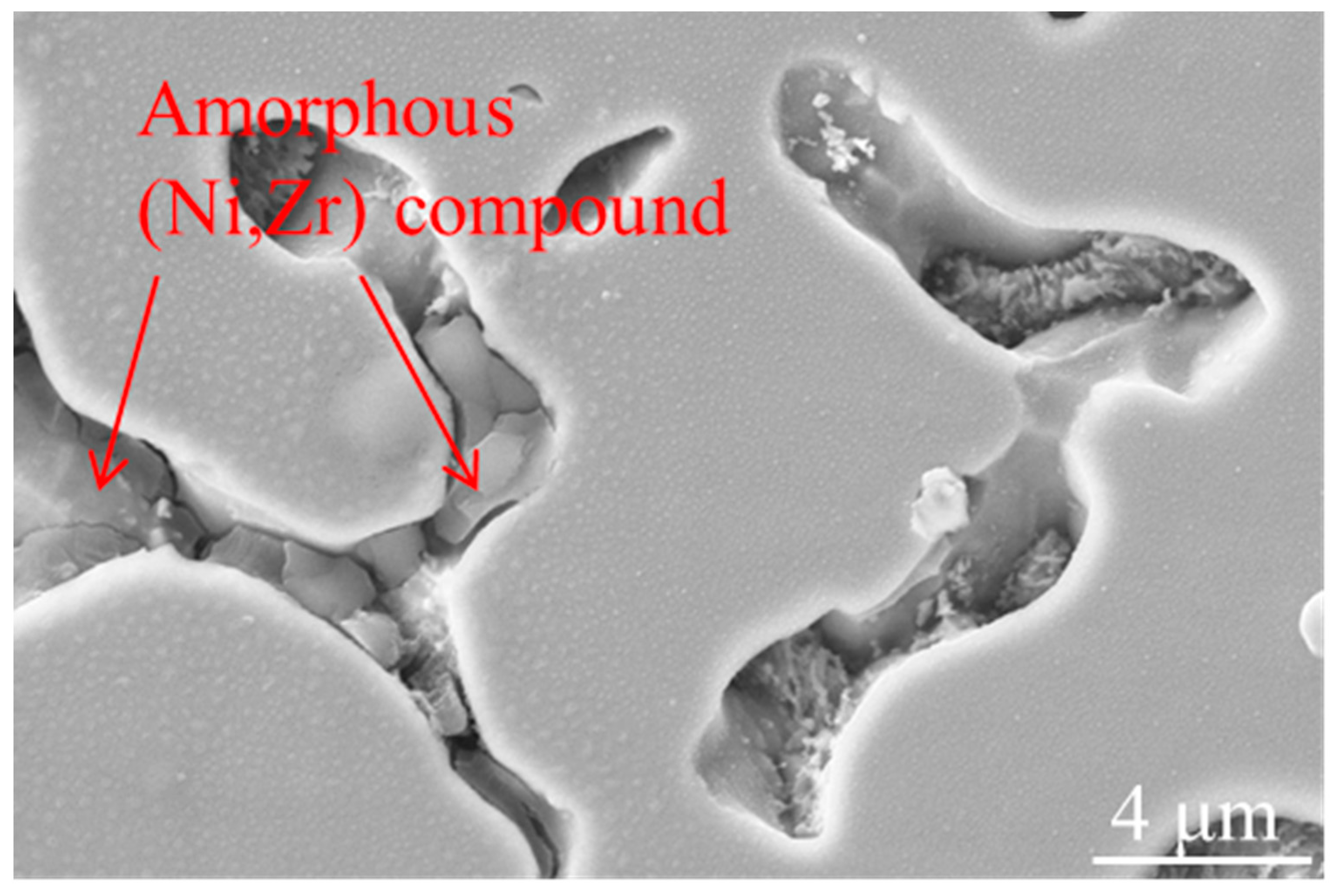
- The three ZrO2 -added NiCrAlY samples had the similar phase patterns, mainly contained γ-Ni phase and t-NiZr2 phase. (Ni, Zr) intermetallic phase was also generated in the process. The fast-cooling speed caused by the ultrasonic-assisted process could induce the formation of (Ni, Zr) intermetallic compound;
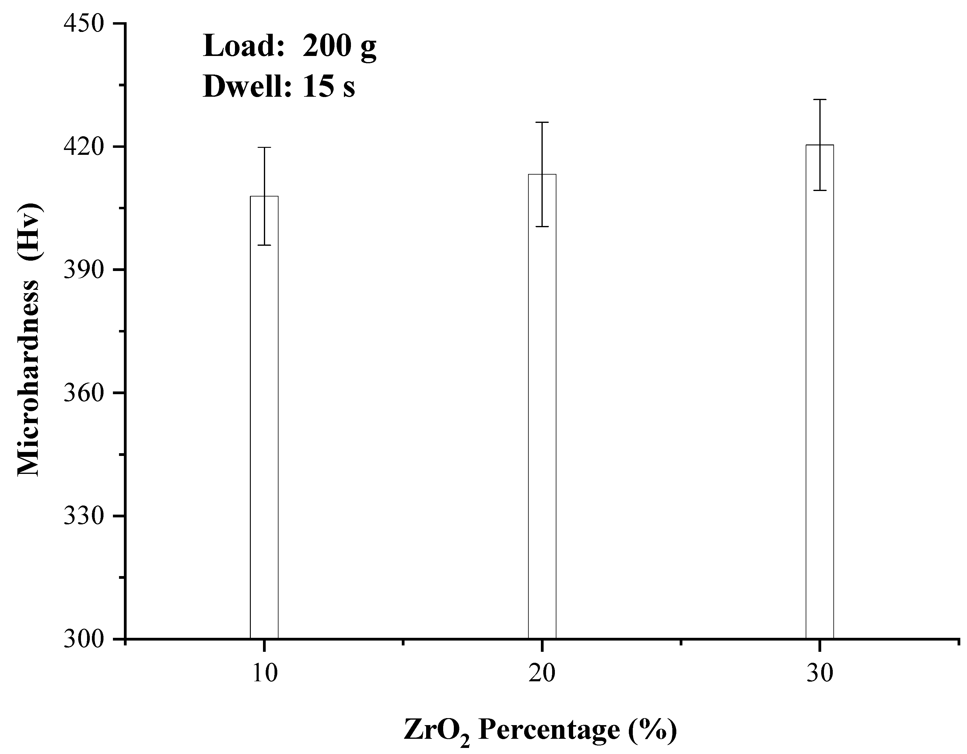
- The microhardness of the composites improved slightly with the increase of ZrO2 content, rising from 407.9 to 420.4 HV. The main reason is that part of the added ZrO2 is lost in the form of oxide scale, and part of ZrO2 forms NiZr2 intermetallic compound, and a small amount of ZrO2 remains in the metal matrix to strengthen the hardness, so the microhardness of the composite has little change;
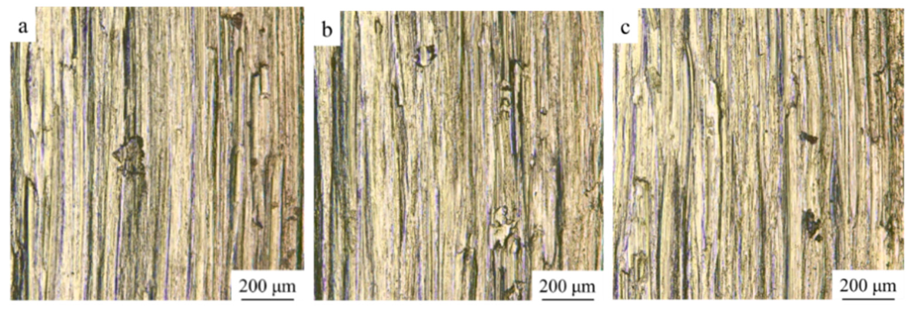
- The wear resistance of the three composites increased with the increase of ZrO2 content. The values of wear mass loss declined, as the maximum drop 22.7%. The wear mechanism for the three composites was mainly abrasive wear with slight adhesive wear. There is no obvious change in the wear mechanism of different composites.
Author Contributions
Funding
Institutional Review Board Statement
Informed Consent Statement
Data Availability Statement
Conflicts of Interest
References
- Li, B.; Gao, Y.M.; Li, C.; Guo, H.J.; Zheng, Q.L.; Li, Y.F.; Kang, Y.C.; Zhao, S.Y. Tribocorrosion Properties of NiCrAlY Coating in Different Corrosive Environments. Materials 2020, 13, 1864. [Google Scholar] [CrossRef] [PubMed]
- Guo, C.A.; Zhou, F.; Chen, M.H.; Wang, J.L.; Zhu, S.L.; Wang, F.H. An in-situ formed ceramic/alloy/ceramic sandwich barrier to resist elements interdiffusion between NiCrAlY coating and a Ni-based superalloy. J. Mater. Sci. Technol. 2021, 70, 1–11. [Google Scholar] [CrossRef]
- Cao, S.; Ren, S.; Zhou, J.; Yu, Y.; Wang, L.; Guo, C.; Xin, B. Influence of composition and microstructure on the tribological property of SPS sintered MCrAlY alloys at elevated temperatures. J. Alloys Compd. 2018, 740, 790–800. [Google Scholar] [CrossRef]
- Demirci, M.; Bagci, M. High temperature solid particle erosion comparison of atmospheric plasma sprayed MCrAlY coatings. Surf. Topogr.-Metrol. Prop. 2021, 9, 035007. [Google Scholar] [CrossRef]
- Wang, J.; Chen, M.; Cheng, Y.; Yang, L.; Bao, Z.; Liu, L.; Zhu, S.; Wang, F. Hot corrosion of arc ion plating NiCrAlY and sputtered nanocrystalline coatings on a nickel-based single-crystal superalloy. Corros. Sci. 2017, 125, 27–39. [Google Scholar] [CrossRef]
- Zhou, L.; Zhou, W.; Luo, F.; Su, J.; Zhu, D.; Dong, Y. Microwave dielectric properties of low power plasma sprayed NiCrAlY/Al2O3 composite coatings. Surf. Coat. Technol. 2012, 210, 122–126. [Google Scholar] [CrossRef]
- Tahari, M.; Shamanian, M.; Salehi, M. The effect of heat treatment and thermal spray processes on the grain growth of nanostructured composite CoNiCrAlY/YSZ powders. J. Alloys Compd. 2015, 646, 372–379. [Google Scholar] [CrossRef]
- Shi, P.Y.; Wang, W.Z.; Wan, S.H.; Gao, Q.; Sun, H.W.; Feng, X.C.; Yi, G.W.; Xie, E.Q.; Wang, Q.H. Tribological performance and high temperature oxidation behaviour of thermal sprayed Ni- and NiCrAlY-based composite coatings. Surf. Coat. Technol. 2021, 405, 126615. [Google Scholar] [CrossRef]
- Vallejo, N.D.; Sanchez, O.; Caicedo, J.C.; Aperador, W.; Zambrano, G. Hot Corrosion of Yttrium Stabilized Zirconia Coatings Deposited by Air Plasma Spray on a Nickel-Based Superalloy. Surf. Rev. Lett. 2017, 24, 1750084. [Google Scholar] [CrossRef]
- Zhu, C.; Wang, Y.G.; An, L.N.; Javed, A.; Xiao, P.; Liang, G.Y. Microstructure and oxidation behavior of conventional and pseudo graded NiCrAlY/YSZ thermal barrier coatings produced by supersonic air plasma spraying process. Surf. Coat. Technol. 2015, 272, 121–128. [Google Scholar] [CrossRef]
- Khoddami, A.M.; Sabour, A.; Hadavi, S.M.M. Microstructure formation in thermally-sprayed duplex and functionally graded NiCrAlY/Yttria-Stabilized Zirconia coatings. Surf. Coat. Technol. 2007, 201, 6019–6024. [Google Scholar] [CrossRef]
- Richer, P.; Yandouzi, M.; Beauvais, L.; Jodoin, B. Oxidation behaviour of CoNiCrAlY bond coats produced by plasma, HVOF and cold gas dynamic spraying. Surf. Coat. Technol. 2010, 204, 3962–3974. [Google Scholar] [CrossRef]
- Bolelli, G.; Candeli, A.; Lusvarghi, L.; Ravaux, A.; Cazes, K.; Denoirjean, A.; Valette, S.; Chazelas, C.; Meillot, E.; Bianchi, L. Tribology of NiCrAlY+ Al2O3 composite coatings by plasma spraying with hybrid feeding of dry powder+ suspension. Wear 2015, 344–345, 69–85. [Google Scholar] [CrossRef]
- Demian, C.; Denoirjean, A.; Pawlowski, L.; Denoirjean, P.; Ouardi, R.E. Microstructural investigations of NiCrAlY+ Y2O3 stabilized ZrO2 cermet coatings deposited by plasma transferred arc (PTA). Surf. Coat. Technol. 2016, 300, 104–109. [Google Scholar] [CrossRef]
- Li, C.G.; Zhang, Q.S.; Wang, F.F.; Deng, P.R.; Lu, Q.H.; Zhang, Y.F.; Li, S.; Ma, P.; Li, W.G.; Wang, Y. Microstructure and wear behaviors of WC-Ni coatings fabricated by laser cladding under high frequency micro-vibration. Appl. Surf. Sci. 2019, 485, 513–519. [Google Scholar] [CrossRef]
- Liu, H.X.; Xu, Q.; Wang, C.Q.; Zhang, X.W. Corrosion and wear behavior of Ni60CuMoW coatings fabricated by combination of laser cladding and mechanical vibration processing. J. Alloys Compd. 2015, 621, 357–363. [Google Scholar] [CrossRef]
- Li, C.G.; Sun, S.; Liu, C.M.; Lu, Q.H.; Ma, P.; Wang, Y. Microstructure and mechanical properties of TiC/AlSi10Mg alloy fabricated by laser additive manufacturing under high-frequency micro-vibration. J. Alloys Compd. 2019, 794, 236–246. [Google Scholar] [CrossRef]
- Parandoush, P.; Fernando, P.; Zhang, H.; Ye, C.; Xiao, J.F.; Zhang, M.; Lin, D. A finishing process via ultrasonic drilling for additively manufactured carbon fiber composites. Rapid Prototyp. J. 2021, 27, 754–768. [Google Scholar] [CrossRef]
- Taborda, L.L.L.; Maury, H.; Pacheco, J. Design for additive manufacturing: A comprehensive review of the tendencies and limitations of methodologies. Rapid Prototyp. J. 2021, 27, 918–966. [Google Scholar] [CrossRef]
- Srivastava, S.; Garg, R.K.; Sharma, V.S.; Alba-Baena, N.G.; Sachdeva, A.; Chand, R.; Singh, S. Multi-physics continuum modelling approaches for metal powder additive manufacturing: A review. Rapid Prototyp. J. 2020, 26, 737–764. [Google Scholar] [CrossRef]
- Mantzouris, X.; Zouvelou, N.; Skarmoutsos, D.; Nikolopoulos, P. Interfacial properties and structure stability of Ni/Y2O3-ZrO2-TiO2 cermet anodes for solid oxide fuel cells. J. Mater. Sci. 2005, 40, 2471–2475. [Google Scholar] [CrossRef]
- Eskin, G.I. Broad prospects for commercial application of the ultrasonic (cavitation) melt treatment of light alloys. Ultrason. Sonochem. 2001, 8, 319–325. [Google Scholar] [CrossRef]
- Eskin, G.I. Cavitation mechanism of ultrasonic melt degassing. Ultrason. Sonochem. 1995, 2, 137–141. [Google Scholar] [CrossRef] [Green Version]
- Cao, G.; Konishi, H.; Li, X. Recent developments on ultrasonic cavitation based solidification processing of bulk magnesium nanocomposites. Int. J. Metalcast. 2008, 2, 57–65. [Google Scholar] [CrossRef]
- Shao, Z.W.; Le, Q.C.; Zhang, Z.Q.; Cui, J.Z. Effects of various parameters on ultrasonic separation of inclusions from magnesium alloy melt. Mater. Werkst. 2012, 43, 220–225. [Google Scholar] [CrossRef]
- Kang, S.; Shen, M.; Li, C. Cold Model Experiments and Mechanism on Inclusion Removal by Ultrasonic Horn. In Advanced Materials Research; Trans Tech Publications: Pfaffikon, Swizerland, 2013. [Google Scholar]
- Ansari, M.; Shoja-Razavi, R.; Barekat, M.; Man, H.C. High-temperature oxidation behavior of laser-aided additively manufactured NiCrAlY coating. Corros. Sci. 2017, 118, 168–177. [Google Scholar] [CrossRef]
- Bezencon, C.; Schnell, A.; Kurz, W. Epitaxial deposition of MCrAlY coatings on a Ni-base superalloy by laser cladding. Scr. Mater. 2003, 49, 705–709. [Google Scholar] [CrossRef]
- Reed, R.C. The Superalloys: Fundamentals and Applications; Cambridge University Press: Cambridge, UK, 2008. [Google Scholar]
- Eckert, J.; Schultz, L.; Hellstern, E. Glass-forming range in mechanically alloyed Ni-Zr and the influence of the milling intensity. J. Appl. Phys. 1988, 64, 3224–3228. [Google Scholar] [CrossRef]
- Dai, W.L. Effects of high-intensity ultrasonic-wave emission on the weldability of aluminum alloy 7075-T6. Mater. Lett. 2003, 57, 2447–2454. [Google Scholar] [CrossRef]
- Zhang, C.; Wu, M.; Du, J. Improving weld quality by arc-excited ultrasonic treatment. Tsinghua Sci. Technol. 2001, 6, 475–478. [Google Scholar]
- Liu, K.; Li, Y.; Wang, J.; Ma, Q. Effect of high dilution on the in situ synthesis of Ni-Zr/Zr-Si (B, C) reinforced composite coating on zirconium alloy substrate by laser cladding. Mater. Des. 2015, 87, 66–74. [Google Scholar] [CrossRef]


| NiCrAlY | Ni | Cr | Al | Y |
|---|---|---|---|---|
| Content (wt.%) | 67.70 | 21.65 | 9.94 | 1.08 |
| YSZ | ZrO2 | Y2O3 | HfO2 | TiO2 | I |
|---|---|---|---|---|---|
| Content (wt.%) | 86.42 | 7.13 | 6.24 | 0.13 | 0.05 |
| Laser Power P (W) | Scanning Speed V (mm/min) | Powder Feeding Q (g/min) | Layer Thickness ΔZ (mm) |
|---|---|---|---|
| 560 | 300 | 2.3 | 0.3 |
| Content | Wear Mass Loss (g) | Changing Percentage (%) |
|---|---|---|
| 0% ZrO2 | 0.022 | 0 |
| 20% ZrO2 | 0.020 | −9.1 |
| 30% ZrO2 | 0.017 | −22.7 |
Publisher’s Note: MDPI stays neutral with regard to jurisdictional claims in published maps and institutional affiliations. |
© 2021 by the authors. Licensee MDPI, Basel, Switzerland. This article is an open access article distributed under the terms and conditions of the Creative Commons Attribution (CC BY) license (https://creativecommons.org/licenses/by/4.0/).
Share and Cite
Yi, Z.; Song, C.; Zhang, G.; Tong, T.; Ma, G.; Wu, D. Microstructure and Wear Property of ZrO2-Added NiCrAlY Prepared by Ultrasonic-Assisted Direct Laser Deposition. Materials 2021, 14, 5785. https://doi.org/10.3390/ma14195785
Yi Z, Song C, Zhang G, Tong T, Ma G, Wu D. Microstructure and Wear Property of ZrO2-Added NiCrAlY Prepared by Ultrasonic-Assisted Direct Laser Deposition. Materials. 2021; 14(19):5785. https://doi.org/10.3390/ma14195785
Chicago/Turabian StyleYi, Zhengyao, Chenchen Song, Guohui Zhang, Tianqi Tong, Guangyi Ma, and Dongjiang Wu. 2021. "Microstructure and Wear Property of ZrO2-Added NiCrAlY Prepared by Ultrasonic-Assisted Direct Laser Deposition" Materials 14, no. 19: 5785. https://doi.org/10.3390/ma14195785
APA StyleYi, Z., Song, C., Zhang, G., Tong, T., Ma, G., & Wu, D. (2021). Microstructure and Wear Property of ZrO2-Added NiCrAlY Prepared by Ultrasonic-Assisted Direct Laser Deposition. Materials, 14(19), 5785. https://doi.org/10.3390/ma14195785