
Flexural Pseudo-Ductility Effect in Hybrid GFRP/CFRP Bars under Static Loading Conditions

 ,
,  ,
, 
 , and
, and 
Abstract
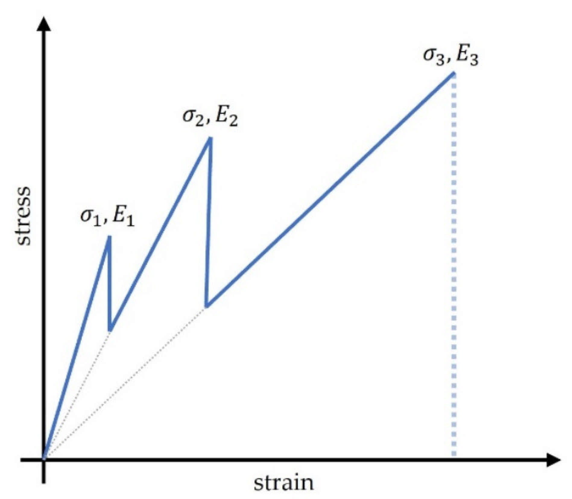
:1. Introduction
2. Materials and Methods
2.1. Materials
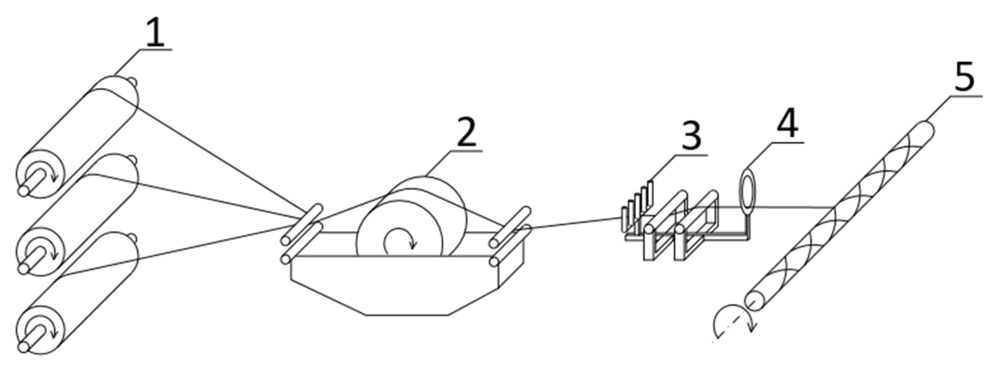
2.2. Filament Winding
2.3. Hand Braiding
- Degreasing the surface of the GFRP/CFRP bars using acetone.
- Stringing the biaxial braided carbon fibre sleeves on the GFRP/CFRP cores.
- Distributing a thin layer of the epoxy resin on the outer surface of the braid.
- Overwrapping with plastic tape to minimize the resin layer.
- Curing in ambient temperature for at least 24 h.
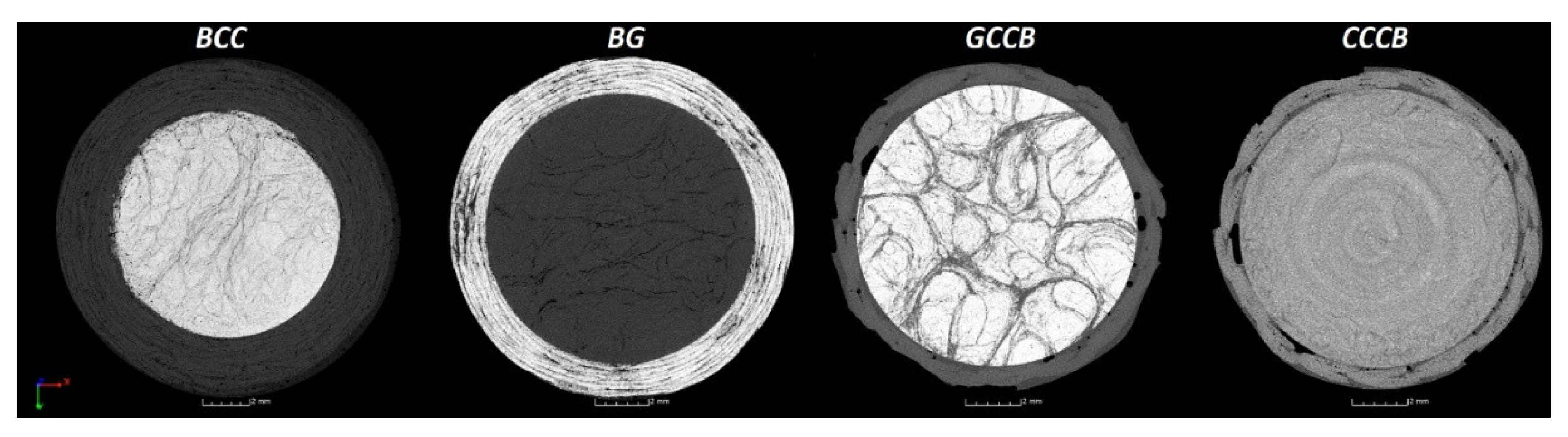
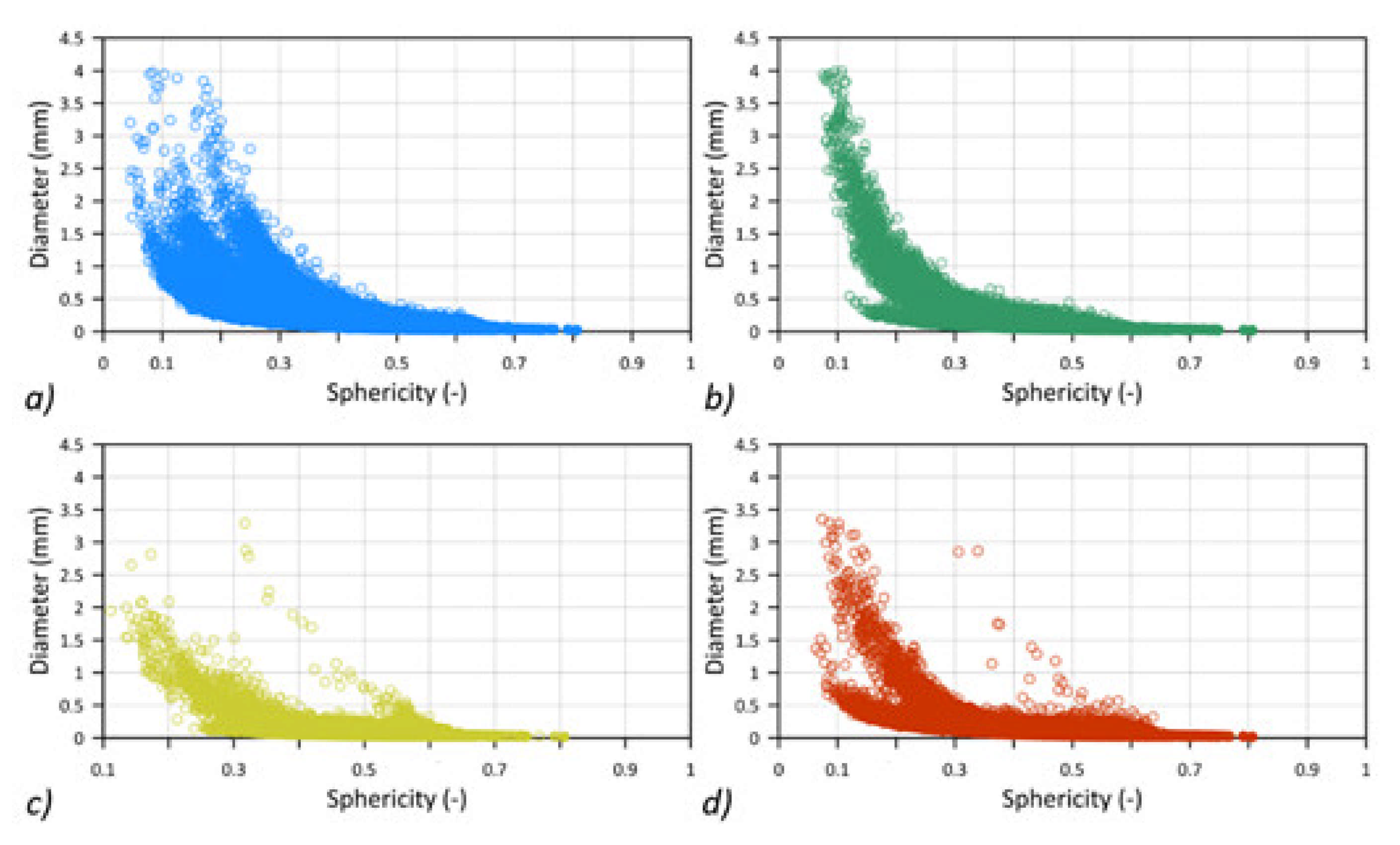
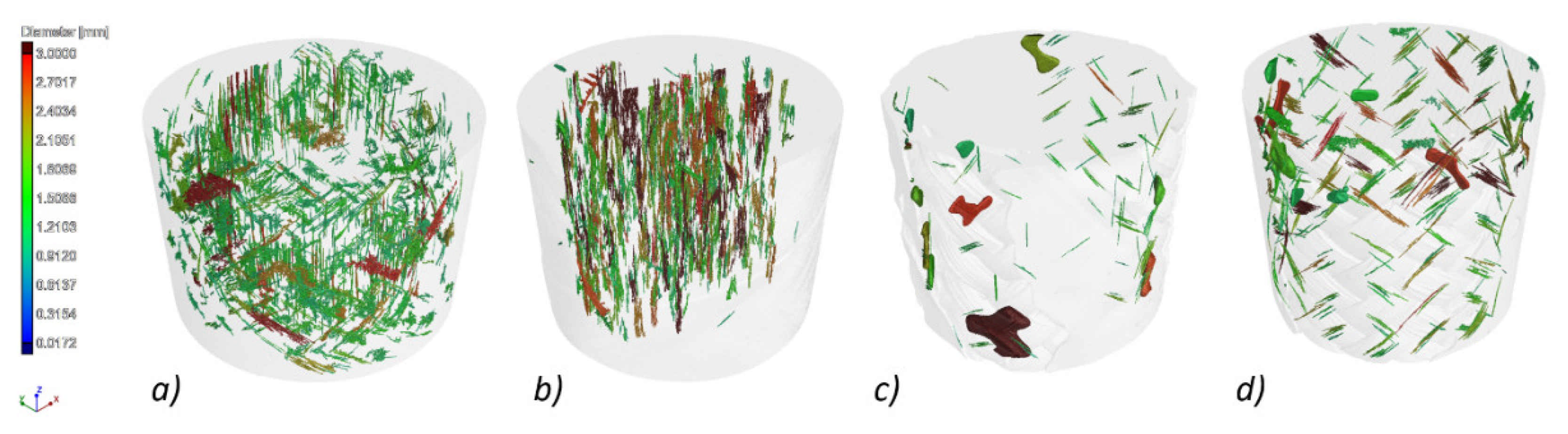
2.4. Microstructural Analysis Using SEM and MikroCT
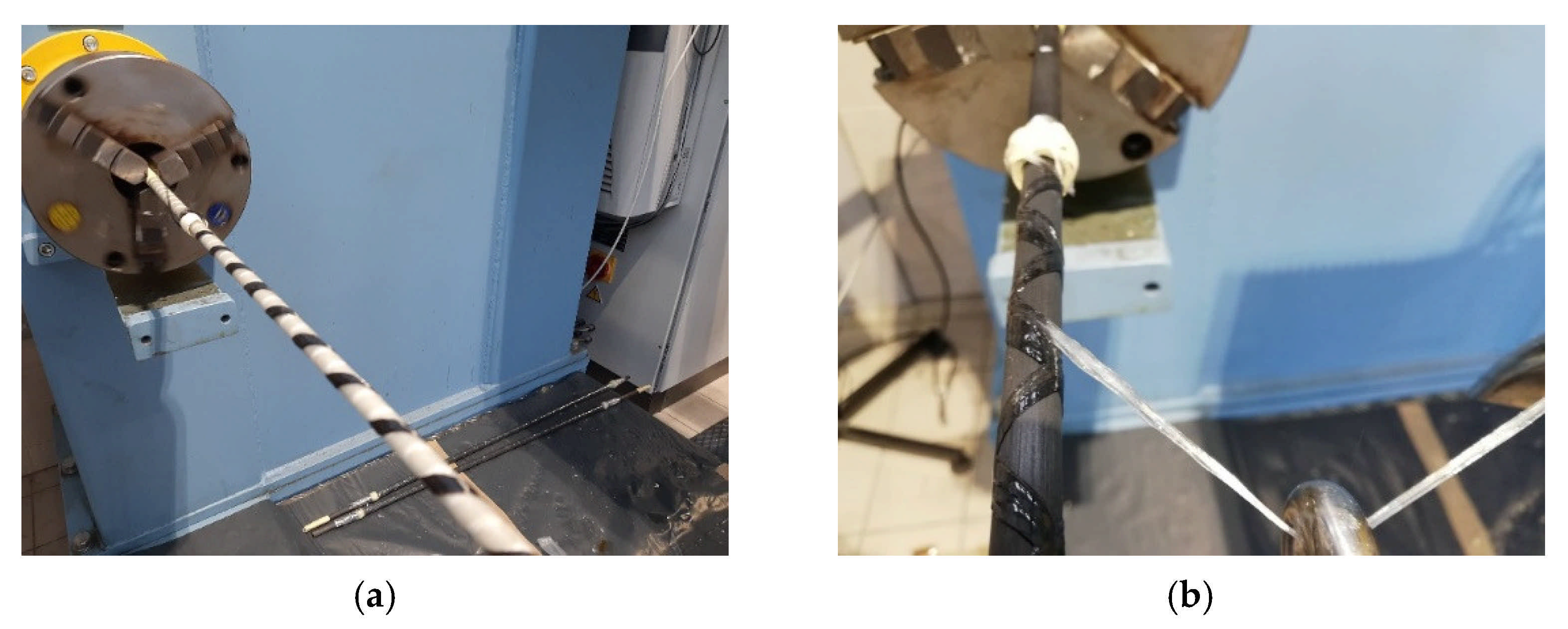
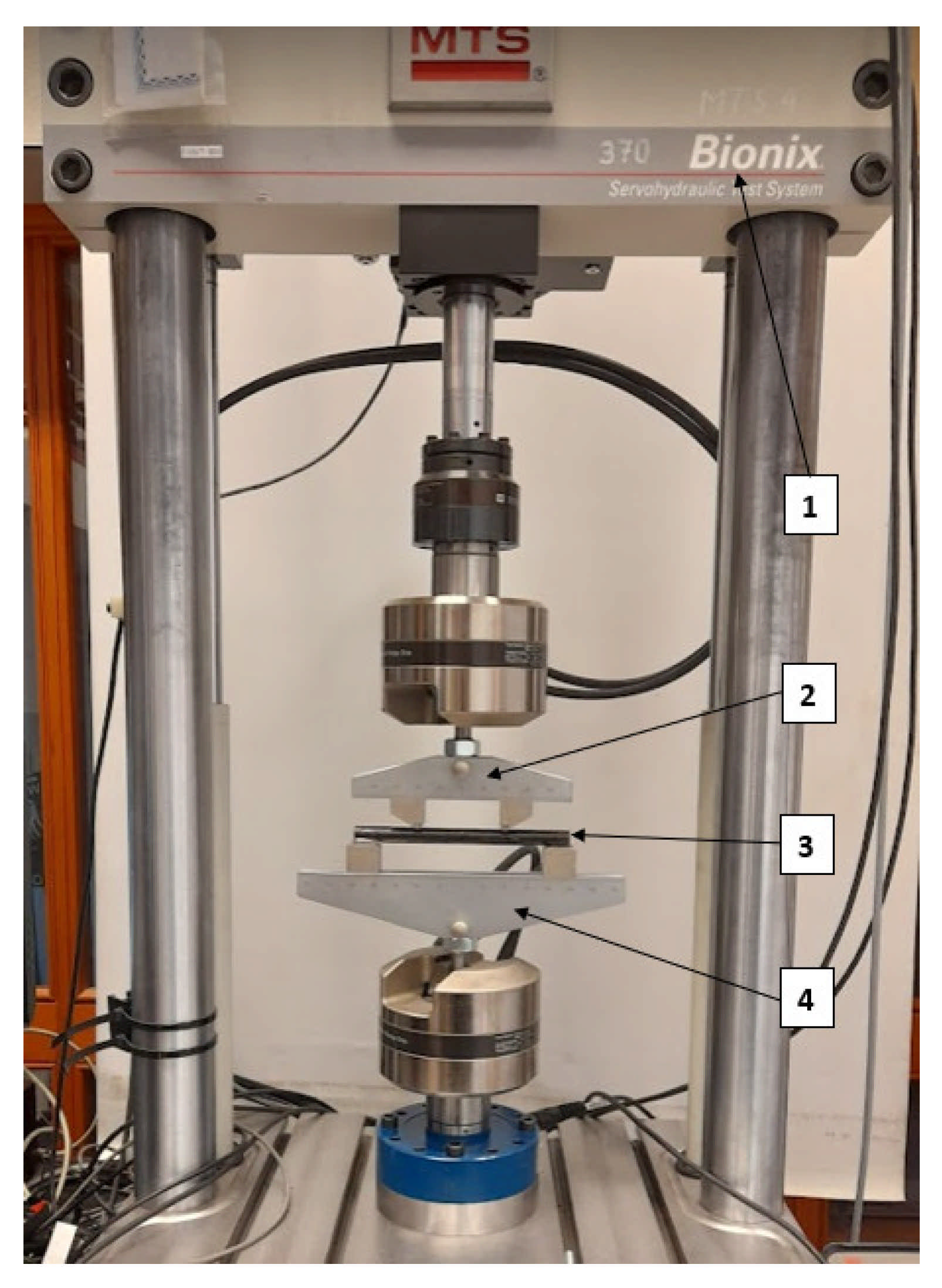
2.5. Bending Test
3. Results
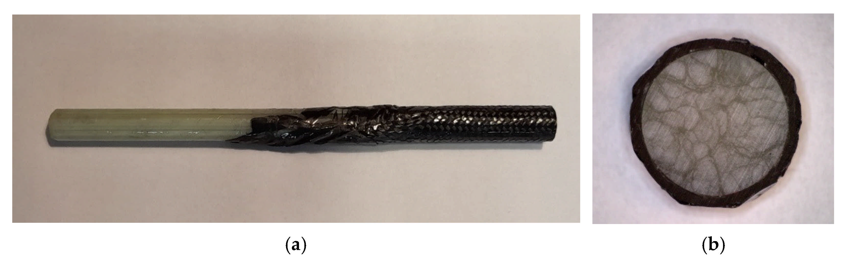
3.1. Microstructural Analysis
3.2. Bending Test Results
4. Conclusions
- The postulated method of using filament winding and a hand braiding technique to obtain the flexural pseudo-ductility effect delivered satisfactory results.
- A microscopic investigation revealed differences between the two techniques. A higher degree of porosity occurred; however, the cross-sections showed better uniformity of the additional layer. On the contrary, the braided layer exhibited lower porosity but with better shape and surface deviations.
- Although characters differed noticeably, the pseudo-ductility effect was observed in filament wound and hand braided bars during a four-point bending static test. In filament wound specimens, the force oscillated significantly around the maximum force, whereas in the hand-braided cases, the force-displacement curves were smoother.
- Post failure macrostructural observations showed that the bars with hand-braided overwrap tended to buckle in the layer in the compressed area. In the filament-wound overwrap, delamination seemed to occur on the core and overwrap layer boundary.
- The above results encourage further research in the optimization of additional layers to obtain the most desirable characteristics of the pseudo-ductility effect.
Author Contributions
Funding
Institutional Review Board Statement
Informed Consent Statement
Data Availability Statement
Conflicts of Interest
References
- Zhang, P.; Hu, R.; Zou, X.; Liu, Y.; Li, Q.; Wu, G.; Ahmed Sheikh, S. Experimental study of a novel continuous FRP-UHPC hybrid beam. Compos. Struct. 2021, 261, 113329. [Google Scholar] [CrossRef]
- Fang, H.; Bai, Y.; Liu, W.; Qi, Y.; Wang, J. Connections and structural applications of fibre reinforced polymer composites for civil infrastructure in aggressive environments. Compos. Part B Eng. 2019, 164, 129–143. [Google Scholar] [CrossRef]
- Nanni, A.; Henneke, M.J.; Okamoto, T. Behaviour of concrete beams with hybrid reinforcement. Constr. Build. Mater. 1994, 8, 89–95. [Google Scholar] [CrossRef]
- Harris, H.G.; Somboonsong, W.; Ko, F.K. New Ductile Hybrid FRP Reinforcing Bar for Concrete Structures. J. Compos. Constr. 1998, 2, 28–37. [Google Scholar] [CrossRef]
- Belarbi, A.; Chandrashekhara, K.; Watkins, S.E. Smart composite rebars with enhanced ductility. Proc. Eng. Mech. 1996, 2, 788–791. [Google Scholar]
- Jeong, S.M.; Naaman, A.E. Ductility of concrete beams prestressed with FRP tendons. In Structures Congress—Proceedings, 1st ed.; Spon: London, UK; New York, NY, USA, 1995; Volume 2, pp. 1466–1469. [Google Scholar]
- Jaeger, G.L.; Tadros, G.; Mufti, A.A. The concept of the overall performance factor in rectangular-section reinforced concrete beams. In Proceedings of the 3rd International Symposium on Non-Metallic (FRP) Reinforcement for Concrete Structures, Sapporo, Japan, 14–16 October 1997; pp. 551–558. [Google Scholar]
- Alsayed, S.H.; Alhozaimy, A.M. Ductility of concrete beams reinforced with FRP bars and steel fibers. J. Compos. Mater. 1999, 33, 1792–1806. [Google Scholar] [CrossRef]
- Summerscales, J.; Short, D. Carbon fibre and glass fibre hybrid reinforced plastics. Composites 1978, 9, 157–166. [Google Scholar] [CrossRef]
- Czél, G.; Wisnom, M.R. Demonstration of pseudo-ductility in high performance glass/epoxy composites by hybridisation with thin-ply carbon prepreg. Compos. Part A Appl. Sci. Manuf. 2013, 52, 23–30. [Google Scholar] [CrossRef] [Green Version]
- Swolfs, Y.; Gorbatikh, L.; Verpoest, I. Fibre hybridisation in polymer composites: A review. Compos. Part A Appl. Sci. Manuf. 2014, 67, 181–200. [Google Scholar] [CrossRef]
- Bakis, C.E.; Nanni, A.; Terosky, J.A.; Koehler, S.W. Self-monitoring, pseudo-ductile, hybrid FRP reinforcement rods for concrete applications. Compos. Sci. Technol. 2001, 61, 815–823. [Google Scholar] [CrossRef]
- Won, J.P.; Park, C.G. Effect of environmental exposure on the mechanical and bonding properties of hybrid FRP reinforcing bars for concrete structures. J. Compos. Mater. 2006, 40, 1063–1076. [Google Scholar] [CrossRef]
- Seo, D.-W.; Park, K.-T.; You, Y.-J.; Kim, H.-Y. Enhancement in Elastic Modulus of GFRP Bars by Material Hybridization. Engineering 2013, 5, 865–869. [Google Scholar] [CrossRef] [Green Version]
- Cui, Y.; Cheung, M.M.S.; Noruziaan, B.; Lee, S.; Tao, J. Development of ductile composite reinforcement bars for concrete structures. Mater. Struct. Constr. 2008, 41, 1509–1518. [Google Scholar] [CrossRef]
- Cheung, M.M.S.; Tsang, T.K.C. Behaviour of concrete beams reinforced with hybrid FRP composite rebar. Adv. Struct. Eng. 2010, 13, 81–93. [Google Scholar] [CrossRef]
- Wang, R.; Jiao, W.; Liu, W.; Yang, F. A new method for predicting dome thickness of composite pressure vessels. J. Reinf. Plast. Compos. 2010, 29, 3345–3352. [Google Scholar] [CrossRef]
- Zu, L.; Koussios, S.; Beukers, A. A novel design solution for improving the performance of composite toroidal hydrogen storage tanks. Int. J. Hydrogen Energy 2012, 37, 14343–14350. [Google Scholar] [CrossRef]
- Rafiee, R.; Torabi, M.A. Stochastic prediction of burst pressure in composite pressure vessels. Compos. Struct. 2018, 185, 573–583. [Google Scholar] [CrossRef]
- Błażejewski, W.; Barcikowski, M.; Lubecki, M.; Stabla, P.; Bury, P.; Stosiak, M.; Lesiuk, G. The Mechanical Investigation of Filament-Wound CFRP Structures Subjected to Different Cooling Rates in Terms of Compressive Loading and Residual Stresses—An Experimental Approach. Materials 2021, 14, 1041. [Google Scholar] [CrossRef] [PubMed]
- Stabla, P.; Smolnicki, M.; Błażejewski, W. The Numerical Approach to Mosaic Patterns in Filament-Wound Composite Pipes. Appl. Compos. Mater. 2021, 28, 181–199. [Google Scholar] [CrossRef]
- Almeida, J.H.S.; Ribeiro, M.L.; Tita, V.; Amico, S.C. Damage and failure in carbon/epoxy filament wound composite tubes under external pressure: Experimental and numerical approaches. Mater. Des. 2016, 96, 431–438. [Google Scholar] [CrossRef]
- Almeida, J.H.S.; Bittrich, L.; Jansen, E.; Tita, V.; Spickenheuer, A. Buckling optimization of composite cylinders for axial compression: A design methodology considering a variable-axial fiber layout. Compos. Struct. 2019, 222, 110928. [Google Scholar] [CrossRef]
- Dalibor, I.H.; Lisbôa, T.V.; Marczak, R.J.; Amico, S.C. Optimum slippage dependent, non-geodesic fiber path determination for a filament wound composite nozzle. Eur. J. Mech. A/Solids 2020, 82, 18. [Google Scholar] [CrossRef]
- Lisbôa, T.V.; Almeida, J.H.S.; Dalibor, I.H.; Spickenheuer, A.; Marczak, R.J.; Amico, S.C. The role of winding pattern on filament wound composite cylinders under radial compression. Polym. Compos. 2020, 41, 2446–2454. [Google Scholar] [CrossRef]
- Tong, Y.; Xu, Y. Improvement of crash energy absorption of 2D braided composite tubes through an innovative chamfer external triggers. Int. J. Impact Eng. 2018, 111, 11–20. [Google Scholar] [CrossRef]
- McGregor, C.J.; Vaziri, R.; Poursartip, A.; Xiao, X. Simulation of progressive damage development in braided composite tubes under axial compression. Compos. Part A Appl. Sci. Manuf. 2007, 38, 2247–2259. [Google Scholar] [CrossRef] [Green Version]
- Dorival, O.; Navarro, P.; Marguet, S.; Petiot, C.; Bermudez, M.; Mesnagé, D.; Ferrero, J.F. Experimental study of impact energy absorption by reinforced braided composite structures: Dynamic crushing tests. Compos. Part B Eng. 2015, 78, 244–255. [Google Scholar] [CrossRef] [Green Version]


| Configuration | Core Material (Fibre Volume Fraction%) | Overwrap Material | Overwrap Technique | Total Average Diameter |
|---|---|---|---|---|
| BCC | Glass FRP (~63%) | Carbon FRP | FW | 14.6 mm |
| BG | Carbon FRP (~60%) | Glass FRP | FW | 12.7 mm |
| GCCB | Glass FRP (~58%) | Carbon FRP | Hand braiding | 11.8 mm |
| CCCB | Carbon FRP (~61%) | Carbon FRP | Hand braiding | 11.8 mm |
| GF | Glass FRP (~63%) | None | None | 10.0 mm |
| CF | Carbon FRP (~61%) | None | None | 10.0 mm |
| Parameter | Rod Type 1—BCC | Rod Type 2—BG |
|---|---|---|
| Pultruded core | GRFP | CFRP |
| FW layers | CFRP | GFRP |
| Core diameter | 10 mm | 10 mm |
| FW thickness | 2.3 mm | 1.35 mm |
| Number of FW layers | 3 | 4 |
| Winding angle | 45° | 45° |
| Mosaic pattern | 1/1 | 1/1 |
| Matrix | Araldite LY 1564 + Aradur 3474 | Araldite LY 1564 + Aradur 3474 |
| Specimen | Core Rod | Core-Overwrap Interface | Post-Testing Images of the Fracture after 3PB Experiment |
|---|---|---|---|
BCC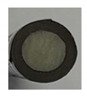 |  | 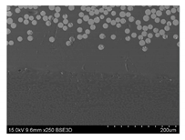 |  |
BG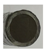 |  | 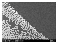 | 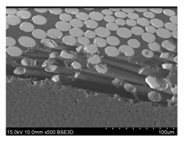 |
CCCB |  | 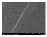 | 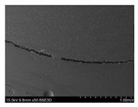 |
GCCB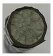 |  | 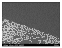 | 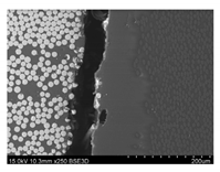 |
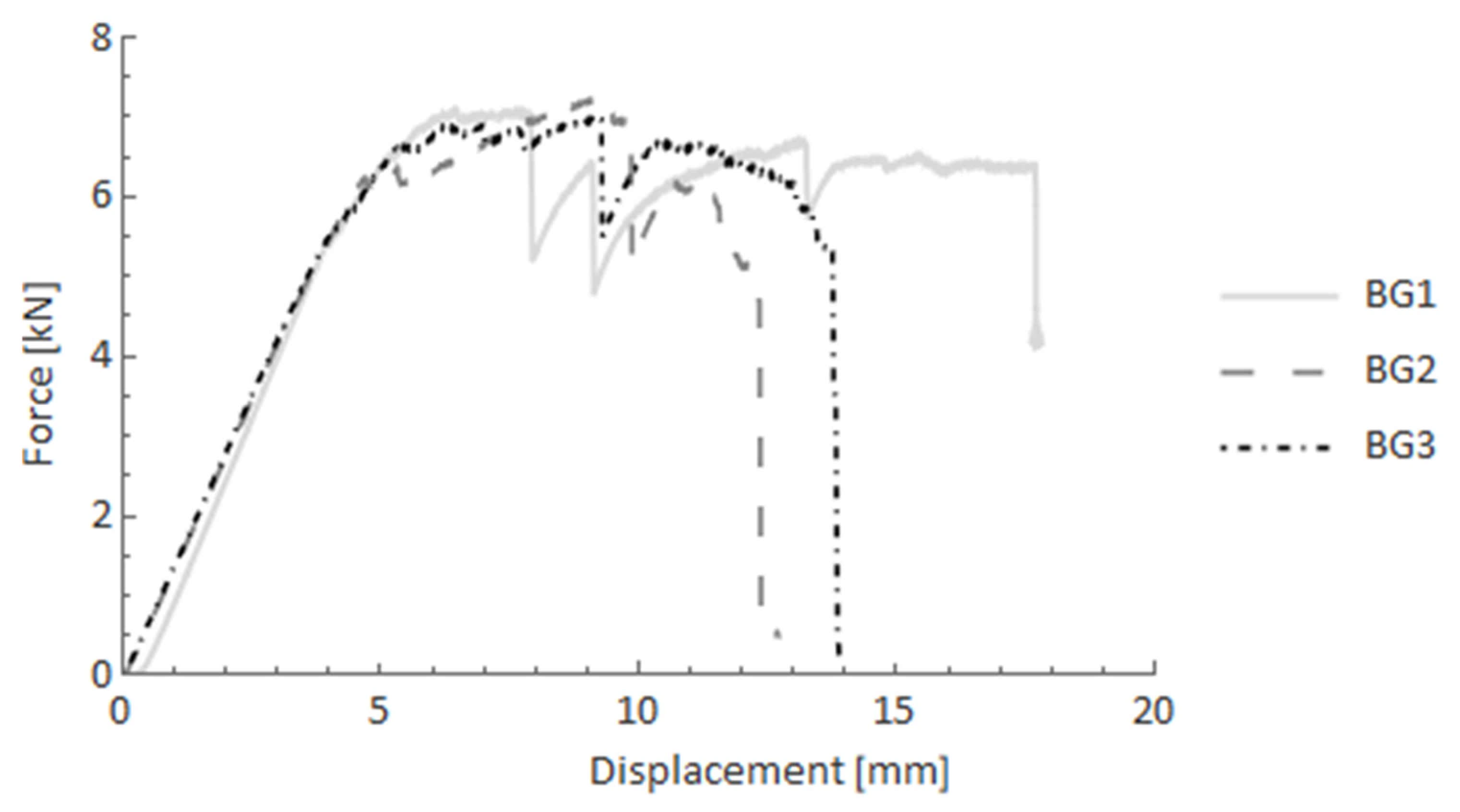
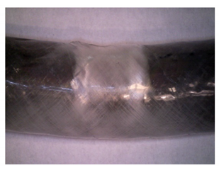 | BG The bars that possess filament–wound composite overwrap exhibit local damage mainly in the overwrap layer in the areas where supports and load were applied. Matrix cracking as well as debonding along the fibres are the primary mechanisms. |
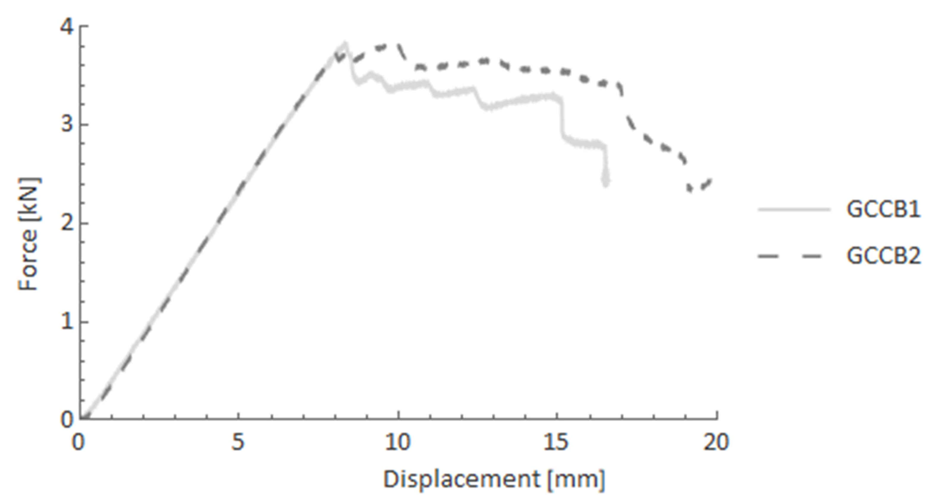
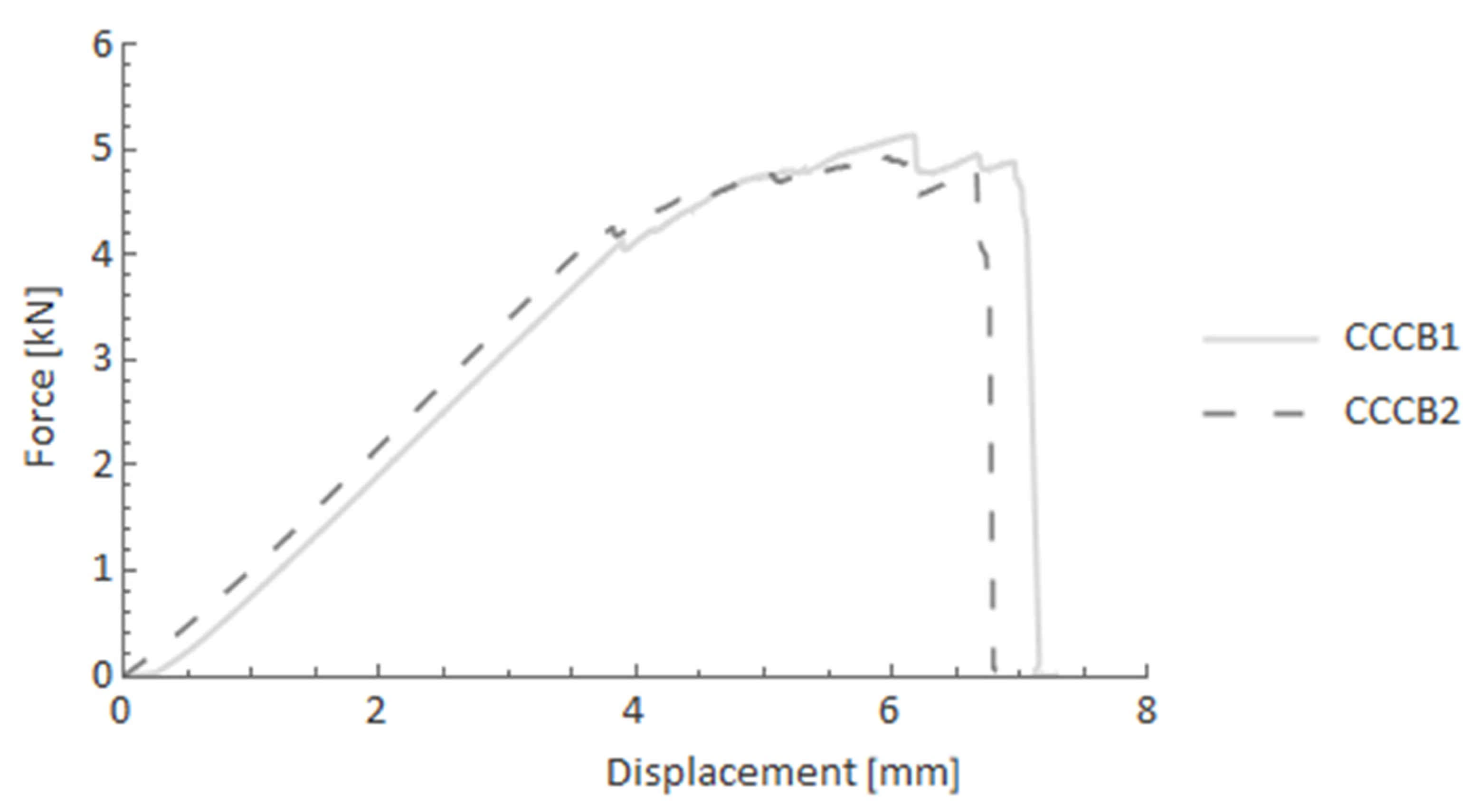
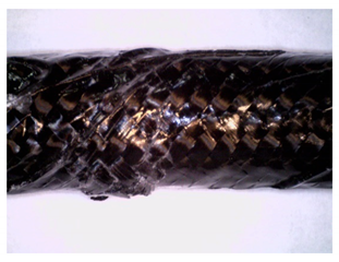 | CCCBA carbon braid manufactured by hand layup protected against sudden stiffness drop. The principal mechanism that occurred in the braided layer in the CCCB and GCCB samples was fibres kinking in the areas of applied supports and load. |
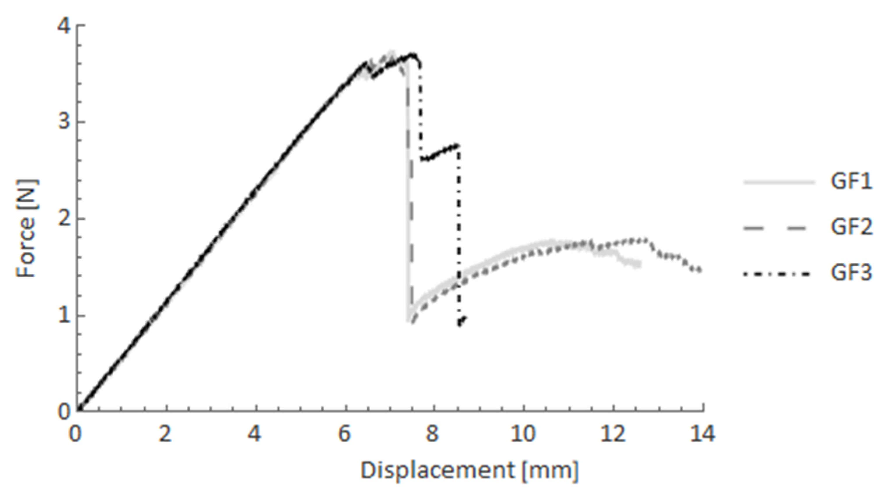
 | GF Pultruded GFRP bars exhibited a sudden drop in stiffness after reaching the maximum force. This was caused by delamination appearing along the fibres in the area of half cross-section perpendicular to the applied force. Local fibre breakage is also visible. |
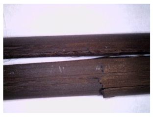 | CF Unidirectional CFRP bars showed behaviour similar to that of the GFRP pultruded bars, with one exception. Their behaviour was not as reapable that for GFRP, and there were a few forces drops, which may imply that adhesion between the matrix and fibres was better for carbon fibres, providing different load-bearing capacity. |
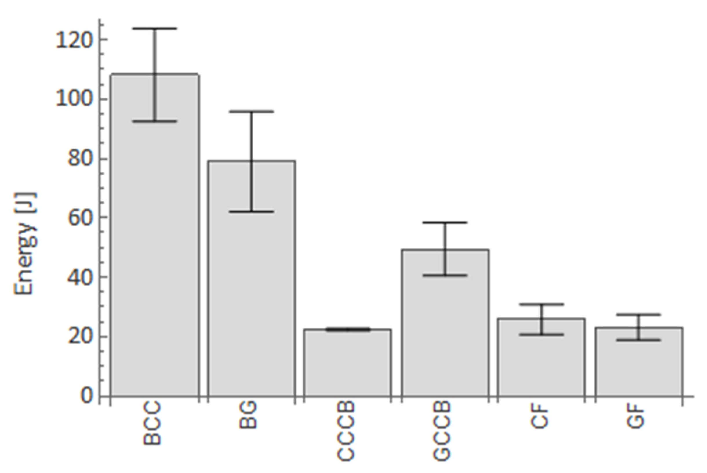
| Specimen | Sample No. | Max. Force (N) | Average Value (N) | Standard Deviation |
|---|---|---|---|---|
| GF | GF1 | 3760.02 | 3729 | 28 |
| GF2 | 3733.81 | |||
| GF3 | 3692.59 | |||
| CF | CF1 | 3735.11 | 3674 | 264 |
| CF2 | 3961.52 | |||
| CF3 | 3324.45 | |||
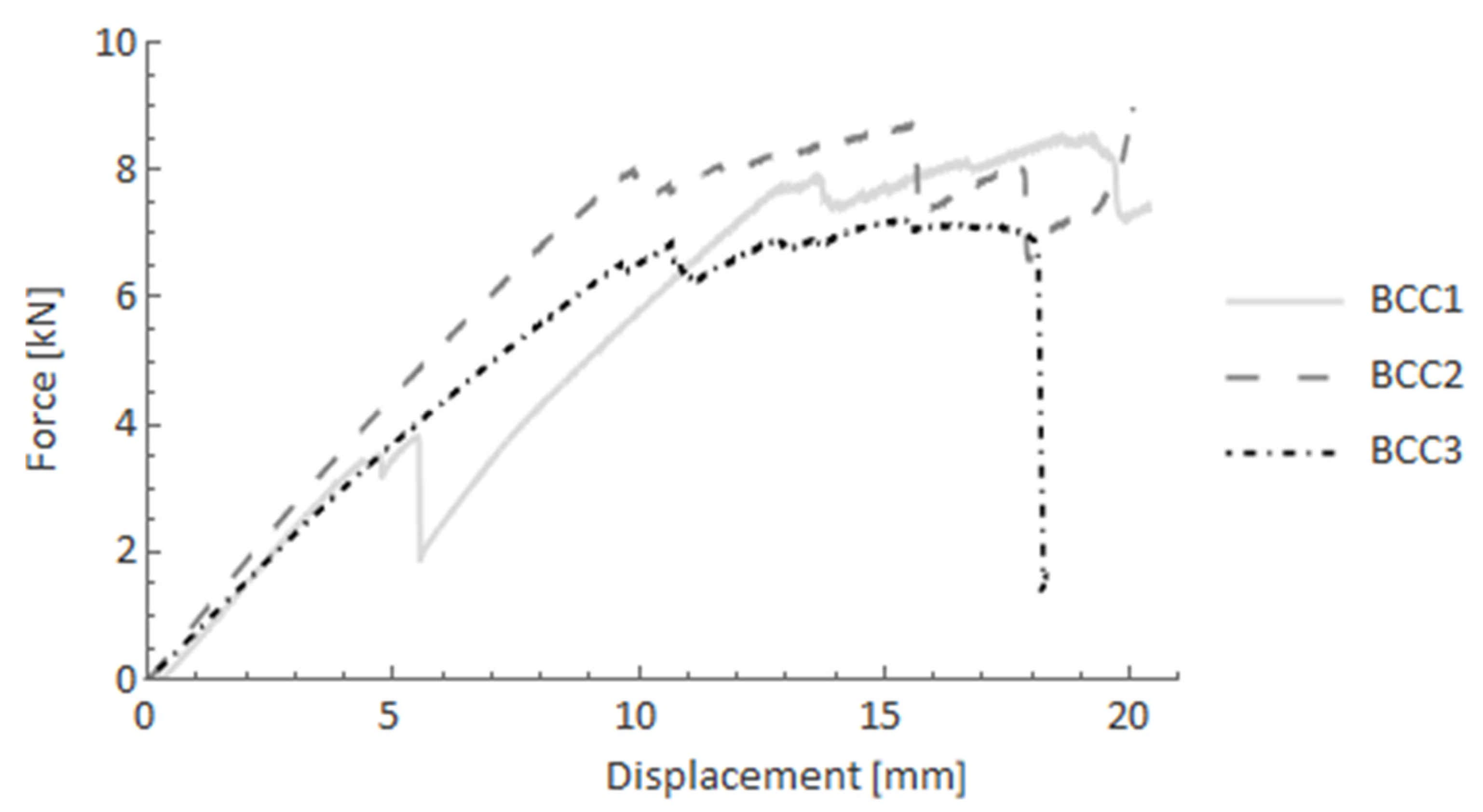
| BCC | BCC1 | 8486.31 | 8275 | 771 |
| BCC2 | 9095.29 | |||
| BCC3 | 7243.49 | |||
| BG | BG1 | 7086.17 | 7128 | 105 |
| BG2 | 7272.71 | |||
| BG3 | 7025.79 | |||
| CCCB | CCCB1 | 5147.73 | 5076 | 72 |
| CCCB2 | 5004.22 | |||
| GCCB | GCCB1 | 3853.05 | 3849 | 4 |
| GCCB2 | 3844.31 |
Publisher’s Note: MDPI stays neutral with regard to jurisdictional claims in published maps and institutional affiliations. |
© 2021 by the authors. Licensee MDPI, Basel, Switzerland. This article is an open access article distributed under the terms and conditions of the Creative Commons Attribution (CC BY) license (https://creativecommons.org/licenses/by/4.0/).
Share and Cite
Duda, S.; Lesiuk, G.; Zielonka, P.; Stabla, P.; Lubecki, M.; Ziółkowski, G. Flexural Pseudo-Ductility Effect in Hybrid GFRP/CFRP Bars under Static Loading Conditions. Materials 2021, 14, 5608. https://doi.org/10.3390/ma14195608
Duda S, Lesiuk G, Zielonka P, Stabla P, Lubecki M, Ziółkowski G. Flexural Pseudo-Ductility Effect in Hybrid GFRP/CFRP Bars under Static Loading Conditions. Materials. 2021; 14(19):5608. https://doi.org/10.3390/ma14195608
Chicago/Turabian StyleDuda, Szymon, Grzegorz Lesiuk, Paweł Zielonka, Paweł Stabla, Marek Lubecki, and Grzegorz Ziółkowski. 2021. "Flexural Pseudo-Ductility Effect in Hybrid GFRP/CFRP Bars under Static Loading Conditions" Materials 14, no. 19: 5608. https://doi.org/10.3390/ma14195608
APA StyleDuda, S., Lesiuk, G., Zielonka, P., Stabla, P., Lubecki, M., & Ziółkowski, G. (2021). Flexural Pseudo-Ductility Effect in Hybrid GFRP/CFRP Bars under Static Loading Conditions. Materials, 14(19), 5608. https://doi.org/10.3390/ma14195608