Article

Microstructures and Electrical Conduction Behaviors of Gd/Cr Codoped Bi3TiNbO9 Aurivillius Phase Ceramic

1
School of Mechanical Engineering, Chengdu University, Chengdu 610106, China
2
College of Materials Science and Engineering, Sichuan University, Chengdu 610065, China
*
Author to whom correspondence should be addressed.
Materials 2021, 14(19), 5598; https://doi.org/10.3390/ma14195598
Submission received: 31 August 2021 / Revised: 23 September 2021 / Accepted: 23 September 2021 / Published: 26 September 2021
(This article belongs to the Special Issue Microstructural Design and Processing Control of Advanced Ceramics)

Abstract

:
In this work, a kind of Gd/Cr codoped Bi3TiNbO9 Aurivillius phase ceramic with the formula of Bi2.8Gd0.2TiNbO9 + 0.2 wt% Cr2O3 (abbreviated as BGTN−0.2Cr) was prepared by a conventional solid-state reaction route. Microstructures and electrical conduction behaviors of the ceramic were investigated. XRD and SEM detection found that the BGTN−0.2Cr ceramic was crystallized in a pure Bi3TiNbO9 phase and composed of plate-like grains. A uniform element distribution involving Bi, Gd, Ti, Nb, Cr, and O was identified in the ceramic by EDS. Because of the frequency dependence of the conductivity between 300 and 650 °C, the electrical conduction mechanisms of the BGTN−0.2Cr ceramic were attributed to the jump of the charge carriers. Based on the correlated barrier hopping (CBH) model, the maximum barrier height WM, dc conduction activation energy Ec, and hopping conduction activation energy Ep were calculated with values of 0.63 eV, 1.09 eV, and 0.73 eV, respectively. Impedance spectrum analysis revealed that the contribution of grains to the conductance increased with rise in temperature; at high temperatures, the conductance behavior of grains deviated from the Debye relaxation model more than that of grain boundaries. Calculation of electrical modulus further suggested that the degree of interaction between charge carriers β tended to grow larger with rising temperature. In view of the approximate relaxation activation energy (~1 eV) calculated from Z″ and M″ peaks, the dielectric relaxation process of the BGTN−0.2Cr ceramic was suggested to be dominated by the thermally activated motion of oxygen vacancies as defect charge carriers. Finally, a high piezoelectricity of d33 = 18 pC/N as well as a high resistivity of ρdc = 1.52 × 10⁵ Ω cm at 600 °C provided the BGTN−0.2Cr ceramic with promising applications in the piezoelectric sensors with operating temperature above 600 °C.

1. Introduction

Bismuth layer—structured ferroelectric (BLSF) compounds (also called Aurivillius phase compounds), with the general formula [Bi2O2][Am−1BmO3m+1], where A with a dodecahedral coordination is a low valence element (less than or equal to trivalent), B with a octahedral coordination is a transition metal element (e.g., Cr3+, Ce4+, Ti4+, Nb5+, Ta5+, W6+), and 1 ≤ m ≤ 6, constructed by m[ABO3]2− layers that alternate with [Bi2O2]2+ layers [1,2,3]. Due to their relatively high Curie point (TC) and excellent fatigue resistance, they have attracted extensive attention for their potential application in high-temperature piezoelectric systems [4,5] and ferroelectric random-access memory (FeRAM) [6]. However, the piezoelectricity of these compounds is limited because of the 2D orientation restriction of their spontaneous polarization (Ps) rotation and their high coercive fields (Ec), and high conductivity also restricts their applications in high temperature environment [7]. The conductivity mechanisms of most ferroelectric materials are approximately divided into three categories: electronic conduction, oxygen vacancies ionic conduction, and mixed conduction of ions and holes. BLSF compounds’ conduction mechanisms are still indistinct. Various mechanisms have been put forward to explain the conductivity property. These mechanisms may be very correct according to the corresponding experiments, but none of them is widely accepted.
Bi3TiNbO9 (BTN), which is made up of (Bi2O2)2+ layers between which two (BiTiNbO7)2− layers (m = 2) are inserted, has a very high TC of ~914 °C. As a sensing material, BTN is promising for fabricating piezoelectric accelerometers with operating temperature above 500 °C [8], which can be used for the high-temperature vibration monitoring of some large power equipment such as aircraft engines, gas turbines, power generators, etc. However, the piezoactivity of pure BTN ceramics is very low (d33 ≤ 7 pC/N) [9]. The resistivity of BTN is only about 107 Ω·cm at 400 °C, for example [10]. Up to now, most reported studies about BTN have concentrated on its crystal structure [11,12,13,14], the electrical properties of pure BTN ceramics [15,16,17,18], and improvement in its piezoelectric ability [19,20,21]. For example, S.V. Zubkov doped Gd elements in BTN, which can increase the Curie temperature to 950 °C [22]. Gd element was also found to provide high insulation and low loss [23]. Chen et al. codoped W/Cr into Bi4Ti3O12 of BLSFs, which increased the resistivity (σdc (600 °C)) and piezoelectric properties (d33 (RT)) to 2.94 × 10⁶ Ω·cm and 28 pC/N, respectively [24,25]. In addition, Chen et al. codoped Mo/Cr into CaBi2Nb2O9, which increased the multifaceted performances of CaBi2Nb2O9 (d33 = 15 pC/N, TC = 939 °C, σdc (600 °C) = 3.33 × 10⁵ Ω·cm) [26]. However, there has been no significant improvement of the piezoelectric properties of BTN-based ceramics. There is also no clear understanding of their conduction behavior.
In this work, we studied the effects of Gd/Cr codoped on the microstructure, AC conduction mechanisms, and electrical impedance spectrum of BGTN−0.2Cr ceramic, focusing on the effect of grain size on conduction mechanism and impedance spectroscopy. A type of piezoelectric ceramic that can be used as a sensing material for piezoelectric sensors with operating temperatures above 600 °C was developed in this work.

2. Experimental Section

2.1. Sample Preparation

A kind of Gd/Cr codoped Bi3TiNbO9 Aurivillius phase ceramics, with the formula of Bi2.8Gd0.2TiNbO9 + 0.2 wt% Cr2O3 (abbreviated as the BGTN−0.2Cr ceramic hereafter), was prepared by using the conventional solid-state reaction route in two steps. First, the metal oxides Bi2O3 of 99% purity, Gd2O3 of 99.99% purity, TiO2 of 99% purity, and Nb2O5 of 99.99% purity (as raw materials) were weighed according to the stoichiometric ratio (Bi2O3, Gd2O3, TiO2 and Nb2O5 produced in Chron Chemicals, Chengdu, China; Cr2O3 produced in Aladdin, Shanghai, China). These raw materials were mixed evenly by ball milling for 6 h, using alcohol as solvent and zirconia balls as grinding media. The dried mixture was calcined at 850 °C for 4 h to synthesize the components of Bi2.8Gd0.2TiNbO9. Second, the calcined powders, with x wt% Cr2O3 of 99.95% purity added, were ground for 12 h under the same grinding conditions and granulated with polyvinyl alcohol (abbreviated as PVA, produced in Chron Chemicals, Chengdu, China) as a binder. The powders were pressed into discs with a diameter of 10 mm and a thickness of 0.8 mm under an isostatic pressure of 10 MPa. After firing at 650 °C for 2 h to burn out the PVA, these discs were sintered in a sealed alumina crucible at 1100 °C for 2 h to obtain the dense ceramics. Finally, Ag electrodes were screen-printed on both surfaces of the polished ceramics and fired at 700 °C for 10 min. For comparison, the pure Bi3TiNbO9 ceramic was prepared by the same process.

2.2. Sample Characterization

The crystallographic structure of the samples was characterized by X-ray diffractometer (XRD, DX−2700B, HAOYUAN INSTRUMENT, Dandong, China) using CuKα radiation. The microscopic morphology of the samples was observed by scanning electron microscope (SEM, Quanta FEG 250, FEI, Waltham, MA, USA). The elemental analysis of the samples was carried out by the energy-dispersive X-ray spectroscopy (EDS) attached to the scanning electron microscope. In the frequency range of 100 Hz–100 kHz, the dielectric constant and loss of the samples as a function of temperature (room temperature~650 °C) were detected by an LCR meter (TH2829A, Tonghui Electronic, Changzhou, China) attached to a programmable furnace. At various temperatures (room temperature~650 °C), the AC impedance spectrum of the samples as a function of frequency (20 Hz–2 MHz) was measured by using an impedance analyzer (TH2838, Tonghui Electronic) attached to a programmable furnace. The electromechanical resonance spectroscopy of the poled samples was investigated by a broadband LCR digital bridge in the frequency range from 280 to 390 kHz. The planar electromechanical coupling factors kp, mechanical quality factors Qm, and planar frequency constant Np were determined according to Onoe’s equations [27]. The piezoelectric charge coefficient of the samples was measured using a quasistatic d33/d31 m (ZJ−6AN, IACAS, Beijing, China).

3. Results and Discussion

3.1. Phase Structure of Ceramics

Figure 1 shows the XRD analysis of the sintered ceramics. As can be seen from Figure 1a, both for the pure BTN ceramic and the BGTN−0.2Cr ceramic, their observed XRD patterns agree with the standard X-ray diffraction powder patterns from JCPDS card No. 39-0233 well. Therefore, both samples were identified as the pure Bi3TiNbO9 phase with orthorhombic structure and space group of A21am. No second phase was found in the XRD pattern of the BGTN−0.2Cr ceramic. The introduced Gd2O3 and Cr2O3 formed a complete solid solution with Bi3TiNbO9. The strongest diffraction peak of the BGTN−0.2Cr ceramic was the (1 × 1 × 5) peak, which is consistent with the rule of the strongest diffraction peak of BLSF ceramics (1 × 1 × 2m + 1) [28]. In view of the similar ionic radius, it is believed that Gd3+ (r = 0.0938 nm) entered the A-site (Bi3+: r = 0.103 nm) of the perovskite unit while Cr3+ (r = 0.0615 nm) entered the B-site (Ti4+: r = 0.0605 nm). Meanwhile, the stability of the ABO3—type perovskite structure can be described by the tolerance factor (t), which can be expressed as [29]:
t = r A + r o 2 ( r B + r o )
where rA, rB, and ro are the ionic radii of A, B, and the oxygen ion, respectively. The perovskite structure remains stable when t is between 0.77 and 1.10. However, the value of the tolerance factor may be further limited in BLSF due to the structural incompatibility between the pseudo perovskite layer and the bismuth-oxygen layer, which is caused by the mismatching of their transverse dimension. Subbarao [1] proposed that when m = 2, t is limited in the range of 0.81~0.93. We obtained t = 0.86 for BTN and t = 0.82 for BGTN−0.2Cr. The decrease in the tolerance factor could demonstrate the successful substitution of Gd3+ and Cr3+ for Bi3+ and Ti4+ at the A- and B-sites, respectively, in the perovskite unit of BTN.
The Rietveld refinement was performed for the XRD patterns of the pure BTN ceramic and the BGTN−0.2Cr; the refined factors and cell parameters are shown in Figure 1b,c. When compared with pure BTN, BGTN−0.2Cr showed a contracted unit cell as well as a smaller orthorhombic distortion (a/b). The substitution of Gd3+ for Bi3+ at the A—site tended to induce a principle change in the structural distortion of perovskite blocks composed of (Ti, Nb)O6 octahedrons. However, the substitution of Cr3+ for Ti4+ at the B—site may have decreased the tilting angle of the (Ti, Nb)O6 octahedron, leading to reduced distortion in the perovskite blocks.

3.2. Grain Morphology and Chemical Composition of Ceramics

Figure 2 shows the SEM and EDS analysis of the BGTN−0.2Cr ceramic, focused on its thermal-etched surface. As can be seen from the SEM image inserted in the EDS, a dense microstructure with well-defined grain boundaries was formed in the ceramic. All the grains were closely stacked, with random orientation, which agrees with the weaker intensity of the (0 × 0 × l) diffracted peaks observed in Figure 1. The microstructure was composed of plate−like grains. Such grain growth possessed a high anisotropy such that the length (L) was larger than the thickness (T), which can be attributed to the higher grain growth rate in the direction perpendicular to the c-axis of the BLSF grains [30]. It is well known that the crystal grain aspect ratio (L/T) has a significant influence on the resistivity of BLSF ceramics. A higher aspect ratio is often related to higher resistivity [31]. The average thickness of these plate-like grains was 1.47 μm, while the length was about 8.93 μm. The high aspect ratio, with a L/T value of 6.1, was expected to lend higher resistivity to the BGTN−0.2Cr ceramic. Furthermore, EDS analysis showed that the BGTN−0.2Cr ceramic contained six elements: Bi, Gd, Ti, Nb, Cr, and O. All the elements presented a uniform distribution in the detected zone. Both gadolinium and chromium were successfully incorporated into the BTN.

3.3. Electrical Conduction Behaviors of Ceramics

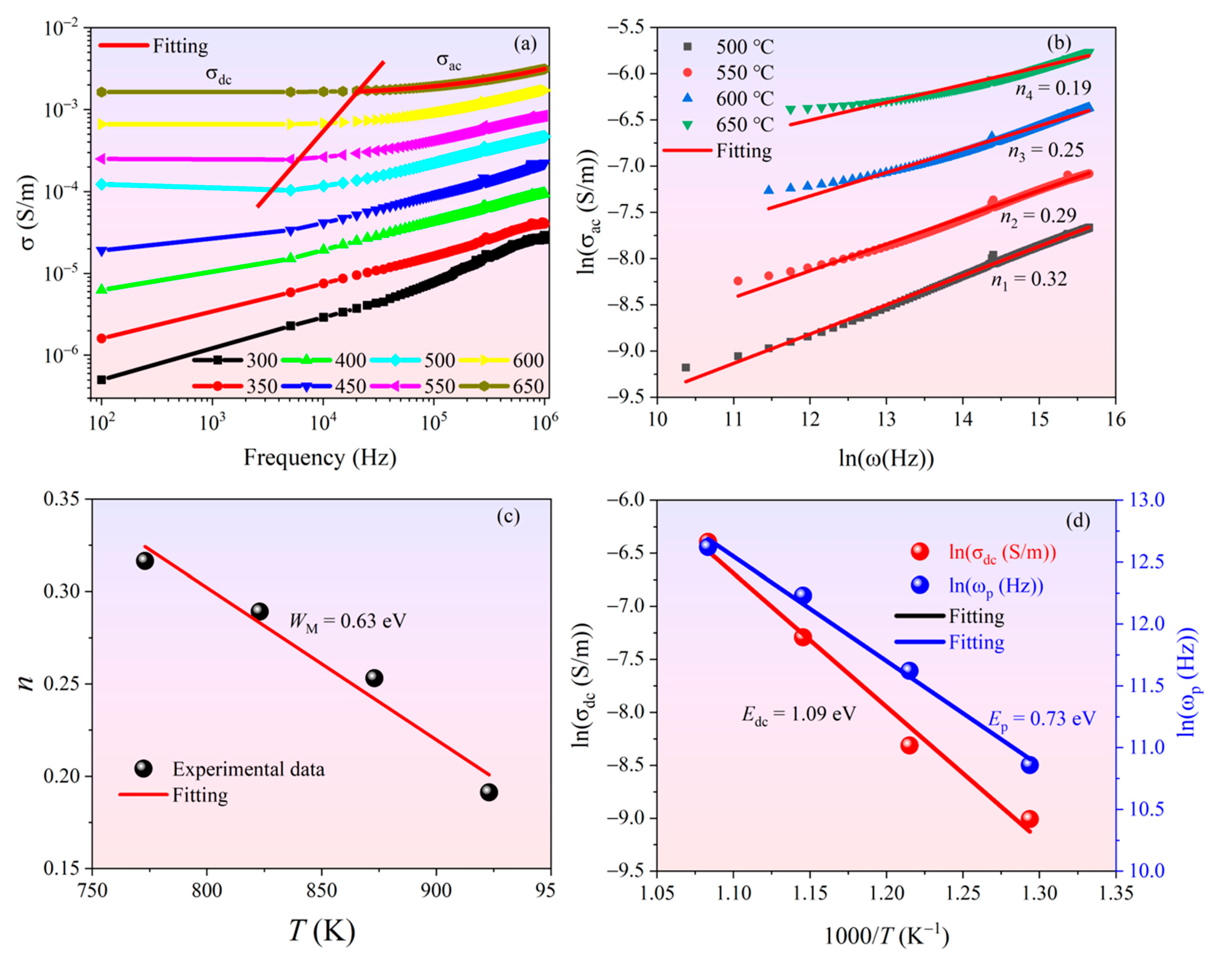
In order to further understand the conduction mechanism at high temperature, the results of electrical conduction spectroscopy of the BGTN−0.2Cr ceramic at high temperature are shown in Figure 3. It can be seen from Figure 3a that the conductivity of the BGTN−0.2Cr ceramic did not change with frequency in the low−frequency section at various temperatures, while in the high-frequency section, the conductivity increased with the increase in frequency. This is consistent with the jump relaxation model proposed by Funke [32]. In the low-frequency section, the migration of charge carriers was mainly implemented through long-distance jump, which led to direct current conductivity. As the frequency increased, the mobility of charge carriers was gradually limited, and the conductivity became positively related to frequency. The functional relationship between conductivity and frequency is consistent with the general Jonscher’s theory [33]:
σ ( ω ) = σ d c ( T ) + A ω n   ( n = 0 ~ 1 )
where σ ( ω ) is the total conductivity, σ d c ( T ) is the dc conductivity, A is a constant with temperature dependence, ω is the angular frequency, n is the frequency index factor, and A ω n represents the ac conductivity. σ d c ( T ) , n, and A can be fitted by Equation (2). Based on Jonscher’s theory, the frequency dependence of ac conductivity originated from the relaxation of the ionic atmosphere after the movement of charge carriers, as shown in Figure 3a.
The changes in the temperature-related frequency index factor n provide information for the origins of conductance. The value of n in the correlated barrier−hopping (CBH) model decreases with temperature rising [34]. The results obtained for the BGTN−0.2Cr ceramic are shown in Figure 3b,c and are well in line with the CBH model. The first-order approximation of the frequency index factor n of the CBH model is given as Equation (3) [35]:
n = 1 6 K B T W M
where WM is the maximum barrier height. The calculated WM (~0.63 eV) was slightly less than the oxygen vacancy’s activation energy (~0.6–1.2 eV), indicating that oxygen vacancies were the main charge carriers between local states. This may be related to the segmental ionization of the first- and second-order oxygen vacancies, which can be expressed by Equations (4) and (5), respectively:
V O V O . + e
V O . V O ¨ + e
where V O . and V O ¨ are the first- and second-stage ionized oxygen vacancies, respectively. In many BLSF materials, the activation energies of the first- and second-stage ionized oxygen vacancies (EI and EII) have been reported as ~0.5 eV and ~1.2 eV, respectively [36]. For instance, EI and EII in SBTW0.04 are 0.57 eV and 0.74 eV [37], and EII in Bi2.8Nd0.2NbTiO9 is 0.9 eV [38]. The conductive and relaxation behaviors related to these BLSF materials can be attributed to long-range/local migration of two-stage ionized oxygen vacancies.
The conductivity of ion conductive materials is related not only to movable ion concentrations but also to ion jump frequencies [39]. The hopping angular frequency ωp of ac conductivity can be fitted by Equation (6), and the activation energy of dc conduction and hopping conduction can be determined and calculated by Arrhenius fitting shown in Equations (7) and (8):
ω p = ( σ a c A ) 1 / n
ω p = ω 0 exp ( E p / k T )
σ d c = σ 0 exp ( E d c / k T )
where ω0 and σ0 are pre−exponential factors, k is the Boltzmann constant, Ep is the activation energy of hopping conduction, and Edc is the dc conduction activation energy. The calculated Edc (~1.09 eV) in Figure 3d was slightly smaller than the activation energy (~1.2 eV) of the second ionized oxygen vacancies, which indicates that V O . and V O ¨ were involved in conduction during the dc conductance process. Furthermore, the reduction of Ep (0.73 eV) indicates that when the oxygen vacancies migrated from long- to short-range jumps, the activation energy decreased, which may have increased the carrier mobility during the ac conduction process. Ep was slightly greater than WM, indicating that carriers were over the barrier height and then had a short-distance jump participation in the ac conduction process. The higher Ep may be also caused by relaxation.
When poled ferroelectric ceramics are used as piezoelectric elements, over time, the polarization change caused by the applied stress is offset by charge movement caused by internal conduction inside the material. At high frequencies, the charge compensation caused by conductivity can be ignored, because the change rate of charge caused by the applied stress is much faster than the time constant (RC). However, at low frequencies, signals from sensors or generators may be significantly attenuated. The minimum useful frequency or lower limit frequency (fLL) is inversely proportional to the time constant, which can be calculated by Equation (9):
f L L = 1 2 π R C = σ 2 π ε
where σ is the dc conductivity, which can be deduced from AC fields below 100 Hz, and ε′ is the real part of the complex dielectric permittivity. It is well known that the RC time constant of BLSF ceramics tends to become very low at high temperature because of the sharp decline of resistivity [40]. In line with Equation (9), the values of fLL in the temperature range of 450–650 °C were calculated for the BGTN−0.2Cr ceramic and are shown in Figure 4. The values of fLL showed a sharp rise when the temperature increased from 450 to 500 °C, and then the increase in fLL with temperature began to slow down when the temperature exceeded 500 °C. In addition to the significant decrease in resistance with temperature, the capacitance of the ferroelectric material is closely related to the temperature. Therefore, the temperature correlation of fLL combines the effects of capacitance and resistance, which can be considered as a useful quality factor for evaluating the service performance of ferroelectric materials.

3.4. Electrical Impedance Spectroscopy of Ceramics

In order to study electrical behavior and distinguish the contribution of grains and grain boundaries to the conductivity of BGTN−0.2Cr ceramic, we analyzed the complex impedance data of BGTN−0.2Cr ceramic, considering both the real (Z′) and imaginary (Z″) parts. The correlation function relationship can be expressed as follows:
Z = Z j Z
Z = R ( 1 + ( ω τ ) 1 α cos [ ( 1 α ) π 2 ] ) 1 + ( ω τ ) 2 ( 1 α ) + 2 ( ω τ ) 1 α cos [ ( 1 α ) π 2 ]
Z = R ( ω τ ) 1 α sin [ ( 1 α ) π 2 ] 1 + ( ω τ ) 2 ( 1 α ) + 2 ( ω τ ) 1 α cos [ ( 1 α ) π 2 ]
where τ = RC and α = 0~1 is the proportion of the relaxation time distribution.
It can be seen from Figure 5a that the impedance value had a monotonous reduction as temperature and frequency rose in the low frequency range (≤10 kHz). The reduction of Z′ as the temperature rose in the low−frequency part suggests that conductivity increased with temperature. It was also seen that while Z′ decreased as frequency increased, after reaching a fixed frequency (≥200 kHz), the value of Z′ became higher as the temperature increased and merged when the frequency increased further. This sudden change represents a possibility that the conductivity increased as frequency and temperature rose because of the fixed carriers at low temperatures and the defects at high temperatures. The combination of Z′ at all temperatures at high frequencies may be due to the release of space charges, which would have led to a decrease in the resistance of the material. Figure 5b shows the change of Z″ with frequency at different temperatures. Obviously, as the frequency increased, Z″ reached a maximum value, which points to the relaxation process in the system. As the temperature increased, the maximum value shifted to higher frequencies. This shows that the relaxation was related to both temperature and frequency. The appropriate temperature activated the particles to cause large motions, and the appropriate frequency caused resonance. When the temperature matched the frequency, the relaxation phenomenon induced was the most obvious (Z″ maximum). It is well known that in perovskite−type compounds, the short-range motion of oxygen vacancies is a common phenomenon that contributes to high-temperature relaxation [41]. Because of the dispersion of bulk grains, Z″ merged at higher frequencies, which signified that the space charge was released. At the same time, the peak value decreased as the temperature increased and tended to become wider. The widening of the peak at higher temperatures indicates the existence of temperature-dependent relaxation. The substances causing relaxation of the material at high temperature may be vacancies or defects [42].
The Nyquist plot (Z″ vs. Z′) from 200 to 650 °C is shown in Figure 5c. The impedance curve at low temperature (~200 °C) was close to the y-axis (imaginary part), which shows the high insulation properties of the ceramic at low temperatures. As the temperature increased, the impedance curve deviated from the y-axis and gradually curved toward the x-axis (real part) to form a deformed, asymmetric, semicircular arc. The asymmetry from the ideal semicircular arc suggests the possibility of multiple relaxation behaviors in BGTN−0.2Cr ceramic. The temperature continued to rise, and the radius of the deformed semicircular arc gradually decreased, indicating that the resistance of the ceramic gradually decreased as the temperature increased.
In order to judge whether multiple relaxation processes existed in BGTN−0.2Cr ceramic, the complex impedance spectrum was analyzed by z-view simulation software. The results are shown in Figure 5d. In the illustration, a resistor Rg and a constant phase element Qg (CPE) connected in parallel represent the contribution of the crystal grain, and the other parallel element (Rgb and Qgb) represents the contribution of the grain boundary. The total resistance of this equivalent circuit can be expressed as:
Z * = R g [ 1 + R g T 1 ( i ω ) n 1 ] + R g b [ 1 + R g b T 2 ( i ω ) n 2 ]
where Rg, Rgb, T1, and T2 are the resistance and variables related to the relaxation time distribution from the grain and grain boundaries, respectively; n (0~1) is the distribution of relaxation time; and n = 1 is the ideal Debye relaxation response. The fitting curve simulated by the Z-View software matched our experimental data well, which confirmed that two kinds of relaxation mechanisms were involved in the BGTN−0.2Cr ceramic, i.e., grain boundaries contributed to the relaxation at low frequency, while grains contributed at high frequency [43]. The results of the simulation analysis showed that the grain boundary resistance (Rgb) was far greater than the bulk grain resistance (Rg) as shown in Figure 5d. This means that at high temperatures, the concentration of oxygen vacancies and captured electronics in the grain boundary was lower. n2 was greater than n1, which indicates that the impedance behavior at the grain boundaries was closer to the ideal Debye relaxation model.
The temperature dependence of Rg and Rgb of the BGTN−0.2Cr ceramic is displayed in Figure 6. The rate at which the grain’s resistance decreased as the temperature rose was slower than that of the grain boundary. The calculation of resistivity and its temperature dependence can be described by the following formulas:
ρ = R S L
ρ = ρ 0 exp ( E con / k T )
where Econ is the activation energy for conduction, ρ0 is the pre-exponential factor, and k is the Boltzmann constant. As shown in Figure 6, as the temperature rose, Eg increased from 0.49 to 1.15 eV, while Egb increases from 0.64 to 1.34 eV. Such a significant increase in the activation energy confirmed that the charge carriers responsible for the electrical conduction process at high temperature changed from the primary−ionized oxygen vacancies to the secondary-ionized ones. No matter what kind of charge carriers dominated the electrical conduction, Eg was always lower than Egb, which implies that the carrier concentration or migration speed of the grains was higher than that of the grain boundaries.

3.5. Electrical Modulus Spectroscopy of Ceramics

The impedance spectrum data emphasized only the maximum resistance element of microscopic components. In order to better understand the relaxation behaviors in BGTN−0.2Cr ceramic, electrical modulus analysis and impedance analysis complemented each other. The modulus spectrum handles the minimum capacitive element of the microscopic components and can suppress electrode interface effects [44,45]. Physically, the electrical modulus corresponds to the relaxation of the electric field in the material when the electric displacement remains constant. Therefore, the electrical modulus represents the real dielectric relaxation process, which can be expressed as:
M = M + j   M = j ω C 0 Z
M = ω C 0 Z
M = j ω C 0 Z
where C0 is the capacitance of free space given by C0 = ε0A/d [46].
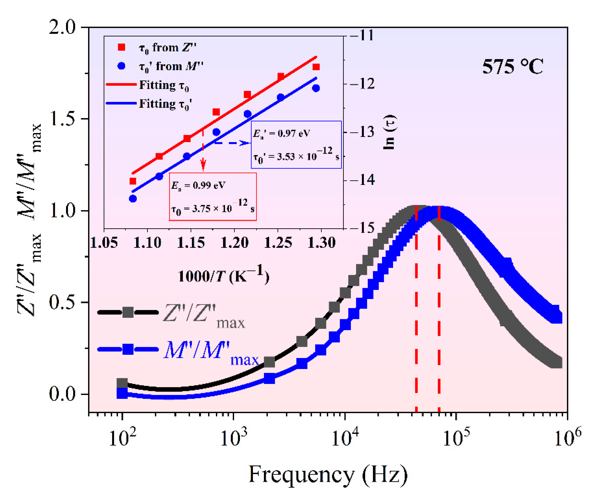
In Figure 7, the electrical modulus spectroscopy of the BGTN−0.2Cr ceramic at high temperature is shown as a function of the frequency with temperature changing. It is obvious from Figure 7a that every temperature showed an identical trend—as frequency rose, M′ values increased, gradually slowing (M′ gradually in a fixed value at higher frequencies). M′ showed asymmetry because of the tensile index characteristics of the relaxation time of materials. The monotonic dispersion in the low-frequency area may be due to the short-range jump of the carriers. This result may be related to the lack of recovery power of the charge carrier migration under the control of the polarization electric field [47]. On the other hand, M″ increased as frequency rose and reached a peak of relaxation because of the bulk grain and grain boundary behaviors. In physics, the electrical modulus peak can determine the area that the charge carrier can be migrated long distance. The asymmetrical and wide M″ peaks imply that the nonexponential behaviors of the grain and grain boundary relaxation deviated from Debye-type relaxation. The behavior indicates that ion migration occurred by jumping accompanying the corresponding time-dependent mobility of other nearby charge carriers [48]. These relaxation peaks moved towards higher frequencies as the temperature increased. With the equation ω τ = 1, we can obtain the relaxation time τ 0 related to the electrical modulus and perform Arrhenius fitting to τ 0 . Comparing the activation energies obtained from the impedance and modulus spectra (Figure 8), we found that the two processes had similar activation energies and pre-exponential factors. This indicates that the two had a common relaxation mechanism—both were dominated by similar carriers. The grain boundaries contributed to low-frequency relaxation, and the grains contributed to high-frequency relaxation.
The M″ curves at different temperatures were normalized to a master curve with the peak position (fmax) and the peak height (Mmax) to research the relaxation process (Figure 7c). The shape of this peak was asymmetrical and wider than Debye-type relaxation. This phenomenon is well described by the Bergman formula [49]:
M ( ω ) = M m a x 1 β + β 1 + β [ β ( ω m a x / ω ) + ( ω / ω m a x ) ] β
where Mmax is the maximum value of M″, ωmax is the angular frequency corresponding to Mmax, and β indicates the extent of deviation from the ideal Debye model—the smaller the value of β, the greater the deviation from Debye−type relaxation (β = 1, see [48]). β increased as temperature rose (Figure 7d), which proves that the relaxation behavior of the BGTN−0.2Cr ceramic grew closer to Debye−type relaxation at higher temperature.
In Figure 8, the frequency dependence of Z″/Zmax and M″/Mmax at 575 °C is shown. It was discovered that the impedance and electrical modulus each showed only one peak of relaxation behaviors. Because of the different focuses of the impedance and modulus, the impedance spectrum with the more resistive grain-boundary component displayed only a single peak, while the single peak of M″/Mmax may be due to the contribution of the grains. The Z″/Zmax peak appeared at a lower frequency, which suggests that the grain boundary gathered a large amount of oxygen vacancies and space charges. The M″/Mmax peak appeared at a higher frequency, which suggests that the grain has a carrier concentration or migration speed below the grain boundary. Ea dominated by Z was slightly larger than Ea’ dominated by M, which once again proves that the activation energy of the grain boundary was slightly larger than that of the grain, as shown in Figure 6.

3.6. Electromechanical Resonance Spectroscopy of Ceramics

Figure 9 shows the electromechanical resonance spectroscopy results for the BTGN−0.2Cr ceramic at room temperature. This measured the frequency dependence of impedance |Z| and the phase angle θ of the piezoceramic as a resonator. The paired peak of resonance-antiresonance around 285.5 kHz showed that the sample was in the radial-extensional vibration mode. In an ideal poling state, piezoelectric materials should exhibit an impedance phase angle θ approaching 90° in the frequency range between the resonance (fr) and antiresonance frequencies (fa). As can be seen, the maximum phase angle θmax was only 36.4°, indicating the insufficient poling of the sample. Since BTN has a high coercive electric field, as well as a low resistivity, a complete domain switching is difficultly achieved by the poling electric field. Things that give satisfaction is that the d33 value of the BTGN−0.2Cr ceramic has reached 18 pC/N, which provides it with a large competitiveness used as sensing materials for high−temperature piezoelectric sensors.

4. Conclusions

An Aurivillius phase ceramic with a formula of Bi2.8Gd0.2TiNbO9 + 0.2 wt% Cr2O3 (abbreviated as BGTN−0.2Cr) was prepared by the conventional solid−state reaction route. Both the microstructures and electrical conduction behaviors of the BGTN−0.2Cr ceramic were studied. The BGTN−0.2Cr ceramic was crystallized in a pure Bi3TiNbO9 phase and composed of plate-like grains. Its ac conduction behavior could be explained by the Funke’s jumping relaxation model. The maximum barrier height WM, hopping conduction activation energy Ep, and dc conduction activation energy Ec were determined to have values of 0.63 eV, 1.09 eV, and 0.73 eV, respectively. Impedance analysis in combination with modulus calculation revealed that grains provided a larger contribution to the conductance at high temperature and that β grew larger as temperature rose. The values of the activation energy (~1 eV) calculated from both Z″ and M″ peaks suggested the electrical relaxation process to be dominated by the thermal activation of oxygen vacancies as defect charge carriers. Moreover, the BGTN−0.2Cr ceramic had a high d33 of 18 pC/N as well as a high σdc of 1.52 × 10⁵ Ω cm (600 °C). Such excellent electrical properties made it a competitive candidate for high−temperature piezoelectric materials.

Author Contributions

H.Z. conceived and designed the experiments; S.W. and D.W. performed the experiments; H.Z. analyzed the data; Q.C. contributed reagents/materials/analysis tools; H.Z. wrote the paper; Y.C. revised the paper. All authors have read and agreed to the published version of the manuscript.

Funding

This work was supported by Applied Basic Research of Sichuan Province (No. 2020YJ0317), the Open project from the Fujian Key Laboratory of Special Advanced Materials (Development of Bi3TiNbO9 High-temperature Piezoceramics, 2021), and the Open project from the Key Laboratory of Deep Earth Science and Engineering, Ministry of Education (DESE202007).

Institutional Review Board Statement

Not applicable.

Informed Consent Statement

Not applicable.

Data Availability Statement

The data presented in this study are available on request from the corresponding author.

Acknowledgments

The authors give thanks for SEM characterization technical support provided by the Institute of Advanced Study at Chengdu University.

Conflicts of Interest

The authors declare no conflict of interest. The authors alone were responsible for the content and writing of this article.

References

  1. Subbarao, E.C. Crystal Chemistry of Mixed Bismuth Oxides with Layer-Type Structure. J. Am. Ceram. Soc. 1962, 45, 166–169. [Google Scholar] [CrossRef]
  2. Aurivillius, B. Mixed Bismuth Oxides with Layer Lattices: I. Arkiv Kemi 1949, 1, 463–480. [Google Scholar]
  3. Newnham, R.E.; Wolfe, R.W.; Dorrian, J.F. Structural basis of ferroelectricity in the bismuth titanate family. Pergamon 1971, 6, 1029–1039. [Google Scholar] [CrossRef]
  4. Pardo, L.; Castro, A.; Millan, P.; Alemany, C.; Jimenez, R.; Jimenez, B. (Bi3TiNbO9)x(SrBi2Nb2O9)1−x aurivillius type structure piezoelectric ceramics obtained from mechanochemically activated oxides. Acta Mater. 2000, 48, 2421–2428. [Google Scholar] [CrossRef]
  5. Hong, S.H.; Trolier-McKinstry, S.; Messing, G.L. Dielectric and Electromechanical Properties of Textured Niobium—Doped Bismuth Titanate Ceramics. J. Am. Ceram. Soc. 2000, 83, 113–118. [Google Scholar] [CrossRef]
  6. De Araujo, C.P.; Cuchiaro, J.D.; McMillan, L.D.; Scott, M.C.; Scott, J.F. Fatigue−free ferroelectric capacitors with platinum electrodes. Nature 1995, 374, 627–629. [Google Scholar] [CrossRef]
  7. Shulman, H.S.; Testorf, M.; Damjanovic, D.; Setter, N. Microstructure, Electrical Conductivity, and Piezoelectric Properties of Bismuth Titanate. J. Am. Ceram. Soc. 1996, 79, 3124–3128. [Google Scholar] [CrossRef]
  8. Thompson, J.G.; Rae, A.D.; Withers, R.L.; Craig, D.C. Revised structure of Bi3TiNbO9. Acta Crystallogr. Sect. B 1991, 47, 174–180. [Google Scholar] [CrossRef]
  9. Zhang, Z.; Yan, H.X.; Dong, X.L.; Wang, Y.L. Preparation and electrical properties of bismuth layer−structured ceramic Bi3NbTiO9 solid solution. Mater. Res. Bull. 2003, 38, 241–248. [Google Scholar] [CrossRef]
  10. Moure, A.; Pardo, L.; Alemany, C.; Millán, P.; Castro, A. Piezoelectric ceramics based on Bi3 TiNbO9 from mechanochemically activated precursors. J. Eur. Ceram. Soc. 2001, 21, 1399–1402. [Google Scholar] [CrossRef]
  11. Wolfe, R.W.; Newnham, R.E.; Smith, D. Crystal structure of Bi3TiNbO9. Ferroelectrics 1972, 3, 1–7. [Google Scholar] [CrossRef]
  12. Withers, R.L.; Thompson, J.G.; Rae, A.D. The crystal chemistry underlying ferroelectricity in Bi4Ti3O12, Bi3TiNbO9, and Bi2WO6. J. Solid. State. Chem. 1991, 94, 404–417. [Google Scholar] [CrossRef]
  13. Yuan, J.; Nie, R.; Chen, Q.; Xiao, D.; Zhu, J. Structural distortion, piezoelectric properties, and electric resistivity of A-site substituted Bi3TiNbO9-based high-temperature piezoceramics. Mater. Res. Bull. 2019, 115, 70–79. [Google Scholar] [CrossRef]
  14. Ricote, J.; Pardo, L.; Moure, A.; Castro, A.; Millán, P.; Chateigner, D. Microcharacterisation of grain-oriented ceramics based on Bi3TiNbO9 obtained from mechanochemically activated precursors. J. Eur. Ceram. Soc. 2001, 21, 1403–1407. [Google Scholar] [CrossRef]
  15. Zhang, Z.; Yan, H.X.; Dong, X.L.; Wang, Y.L. Structural and electrical properties of Bi3NbTiO9 solid solution. J. Inorg. Mater. 2003, 18, 1377–1380. [Google Scholar]
  16. Lisiñska-Czekaj, A.; Czekaj, D.; Gomes, M.J.M.; Kuprianov, M.F. Investigations on the synthesis of Bi3NbTiO9 ceramics. J. Eur. Ceram. Soc. 1999, 19, 969–972. [Google Scholar] [CrossRef]
  17. Zhang, Z.; Yan, H.X.; Dong, X.L.; Xiang, P. Grain orientation effects on the properties of a bismuth layer-structured ferroelectric (BLSF) Bi3NbTiO9 solid solution. J. Am. Ceram. Soc. 2004, 87, 602–605. [Google Scholar] [CrossRef]
  18. Moure, A.; Pardo, L. Microstructure and texture dependence of the dielectric anomalies and dc conductivity of Bi3TiNbO9 ferroelectric ceramics. J. Appl. Phys. 2005, 97, 084103. [Google Scholar] [CrossRef] [Green Version]
  19. Peng, Z.H.; Yan, D.X.; Chen, Q.; Xin, D. Crystal structure, dielectric and piezoelectric properties of Ta/W codoped Bi3TiNbO9 Aurivillius phase ceramics. Curr. Appl. Phys. 2014, 14, 1861–1866. [Google Scholar] [CrossRef]
  20. Bekhtin, M.A.; Bush, A.A.; Kamentsev, K.E.; Segalla, A.G. Preparation and Dielectric and Piezoelectric Properties of Bi3TiNbO9, Bi2CaNb2O9, and Bi2.5Na0.5Nb2O9 Ceramics Doped with Various Elements. Neorg. Mater. 2016, 52, 557–563. [Google Scholar] [CrossRef]
  21. Zhang, F.Q.; Wahyudi, O.; Liu, Z.F.; Gu, H. Preparation and electrical properties of a new−type intergrowth bismuth layer−structured (Bi3TiNbO9)1(Bi4Ti3O12)2 ceramics. J. Alloys Compd. 2018, 753, 54–59. [Google Scholar] [CrossRef]
  22. Zubkov, S.V. Crystal structure and dielectric properties of layered perovskite−like solid solutions Bi3−xGdxTiNbO9 (x = 0, 0.1, 0.2, 0.3) with high Curie temperature. J. Adv. Dielectr. 2020, 10, 2060002. [Google Scholar] [CrossRef] [Green Version]
  23. Groń, T.; Maciejkowicz, M.; Tomaszewicz, E.; Guzik, M.; Oboz, M.; Sawicki, B.; Pawlus, S.; Nowok, A.; Kukuła, Z. Combustion synthesis, structural, magnetic and dielectric properties of Gd3+−doped lead molybdato-tungstates. J.Adv. Ceram. 2020, 9, 255–268. [Google Scholar] [CrossRef] [Green Version]
  24. Chen, Y.; Peng, Z.H.; Wang, Q.Y.; Zhu, J. Crystalline structure, ferroelectric properties, and electrical conduction characteristics of W/Cr co−doped Bi4Ti3O12 ceramics. J. Alloys Compd. 2014, 612, 120–125. [Google Scholar] [CrossRef]
  25. Chen, Y.; Liang, D.Y.; Wang, Q.Y.; Zhu, J. Microstructures, dielectric, and piezoelectric properties of W/Cr co−doped Bi4Ti3O12 ceramics. J. Appl. Phys. 2014, 116, 074108. [Google Scholar] [CrossRef]
  26. Chen, Z.N.; Zhang, Y.H.; Huang, P.M.; Li, X. Enhanced piezoelectric properties and thermal stability in Mo/Cr co−doped CaBi2Nb2O9 high-temperature piezoelectric ceramics. J. Phys. Chem. Solids 2020, 136, 109195. [Google Scholar] [CrossRef]
  27. Onoe, M.; Jumonji, H. Useful formulas for piezoelectric ceramic resonators and their application to measurement of parameters. J. Acoust. Soc. Am. 1967, 41, 974–980. [Google Scholar] [CrossRef]
  28. Du, X.F.; Chen, I.W. Ferroelectric thin films of bismuth-containing layered perovskites: Part II, PbBi2Nb2O9. J. Am. Ceram. Soc. 1998, 81, 3260–3264. [Google Scholar] [CrossRef]
  29. Li, Z.; Yang, M.J.; Park, J.S.; Wei, S.-H.; Berry, J.J.; Zhu, K. Stabilizing Perovskite Structures by Tuning Tolerance Factor: Formation of Formamidinium and Cesium Lead Iodide Solid−State Alloys. Chem. Mater. 2016, 28, 284–292. [Google Scholar] [CrossRef]
  30. Wang, C.M.; Wang, J.F.; Zhang, S.J.; Shrout, T.R. Electromechanical properties of A−site (LiCe)−modified sodium bismuth titanate (Na0.5Bi4.5Ti4O15) piezoelectric ceramics at elevated temperature. J. Appl. Phys. 2009, 105, 094110. [Google Scholar] [CrossRef]
  31. Peng, Z.H.; Chen, Q.; Chen, Y.; Xiao, D. Microstructure and electrical properties in W/Nb co−doped Aurivillius phase Bi4Ti3O12 piezoelectric ceramics. Mater. Res. Bull. 2014, 59, 125–130. [Google Scholar] [CrossRef]
  32. Jonscher, A.K. Dielectric relaxation in solids. J. Phys. D Appl. Phys. 1999, 32, R57. [Google Scholar] [CrossRef]
  33. Jonscher, A.K. The ‘universal’ dielectric response. Nature 1977, 267, 673–679. [Google Scholar] [CrossRef]
  34. Elliott, S.R. Temperature dependence of ac conductivity of chalcogenide glasses. Philos. Mag. B 1978, 37, 553–560. [Google Scholar] [CrossRef]
  35. Mohamed, C.B.; Karoui, K.; Saidi, S.; Guidara, K.; Rhaiem, A.B. Electrical properties, phase transitions and conduction mechanisms of the [(C2H5)NH3]2CdCl4 compound. Phys. B Condens. Matter. 2014, 451, 87–95. [Google Scholar] [CrossRef]
  36. Singh, G.; Tiwari, V.S.; Gupta, P.K. Role of oxygen vacancies on relaxation and conduction behavior of KNbO3 ceramic. J. Appl. Phys. 2010, 107, 064103. [Google Scholar] [CrossRef]
  37. Nayak, P.; Badapanda, T.; Singh, A.K.; Panigrahi, S. Possible relaxation and conduction mechanism in W6+ doped SrBi4Ti4O15 ceramic. Ceram. Int. 2017, 43, 4527–4535. [Google Scholar] [CrossRef]
  38. Zhang, H.T.; Yan, H.X.; Reece, M.J. The effect of Nd substitution on the electrical properties of Bi3NbTiO9 Aurivillius phase ceramics. J. Appl. Phys. 2009, 106, 044106. [Google Scholar] [CrossRef]
  39. Almond, D.P.; Duncan, G.K.; West, A.R. The determination of hopping rates and carrier concentrations in ionic conductors by a new analysis of ac conductivity. Solid State Ion. 1983, 8, 159–164. [Google Scholar] [CrossRef]
  40. Turner, R.C.; Fuierer, P.A.; Newnham, R.E.; Shrout, T.R. Materials for high temperature acoustic and vibration sensors: A review. Appl. Acoust. 1994, 41, 299–324. [Google Scholar] [CrossRef]
  41. Li, W.; Hao, J.; Du, J.; Fu, P.; Sun, W.; Chen, C.; Xu, Z.; Chu, R. Electrical properties and luminescence properties of 0.96(K0.48Na0.52)(Nb0.95Sb0.05)–0.04Bi0.5(Na0.82K0.18)0.5ZrO3–xSm lead−free ceramics. J. Adv. Ceram. 2020, 9, 72–82. [Google Scholar] [CrossRef] [Green Version]
  42. Sumi, S.; Raon, P.P.; Koshy, P. Impedance spectroscopic investigation on electrical conduction and relaxation in manganese substituted pyrochlore type semicon−ducting oxides. Ceram. Int. 2015, 41, 5992–5998. [Google Scholar] [CrossRef]
  43. Rehman, F.; Li, J.B.; Dou, Y.K.; Zhang, J.S.; Zhao, Y.J.; Rizwan, M.; Khalid, S.; Jin, H.B. Dielectric relaxations and electrical properties of Aurivillius Bi3.5La0.5Ti2Fe0.5Nb0.5O12 Ceramics. J. Alloys Compd. 2016, 654, 315–320. [Google Scholar] [CrossRef]
  44. Wong, Y.J.; Hassan, J.; Hashim, M. Dielectric properties, impedance analysis and modulus behavior of CaTiO3 ceramics prepared by solid state reaction. J. Alloys Compd. 2013, 571, 138–144. [Google Scholar] [CrossRef]
  45. Morrison, F.D.; Sinclair, D.C.; West, A.R. Characterization of Lanthanum-doped barium titanate ceramics using impedance spectroscopy. J. Am. Ceram. Soc. 2001, 84, 531–538. [Google Scholar] [CrossRef]
  46. Mahamoud, H.; Louati, B.; Hlel, F.; Guidara, K. Impedance and modulus analysis of the (Na0.6Ag0.4)2PbP2O7 compound. J. Alloys Compd. 2011, 509, 6083–6089. [Google Scholar] [CrossRef]
  47. Mandal, S.K.; Dey, P.; Nath, T.K. Structural, electrical and dielectric properties of La0.7Sr0.3MnO3–ErMnO3 multiferroic composites. Mater. Sci. Eng. B 2014, 181, 70–76. [Google Scholar] [CrossRef]
  48. Mohanty, V.; Cheruku, R.; Vijayan, L.; Govindaraj, G. Ce-substituted lithium ferrite: Preparation and electrical relaxation studies. J. Mater. Sci. Technol. 2014, 30, 335–341. [Google Scholar] [CrossRef]
  49. Zurbuchen, M.A.; Sherman, V.O.; Tagantsev, A.K.; Schubert, J.; Hawley, M.E.; Fong, D.D.; Streiffer, S.K.; Jia, Y.; Tian, W.; Schlom, G. Synthesis, structure, and electrical behavior of Sr4Bi4Ti7O24. J. Appl. Phys. 2010, 107, 024106. [Google Scholar] [CrossRef] [Green Version]
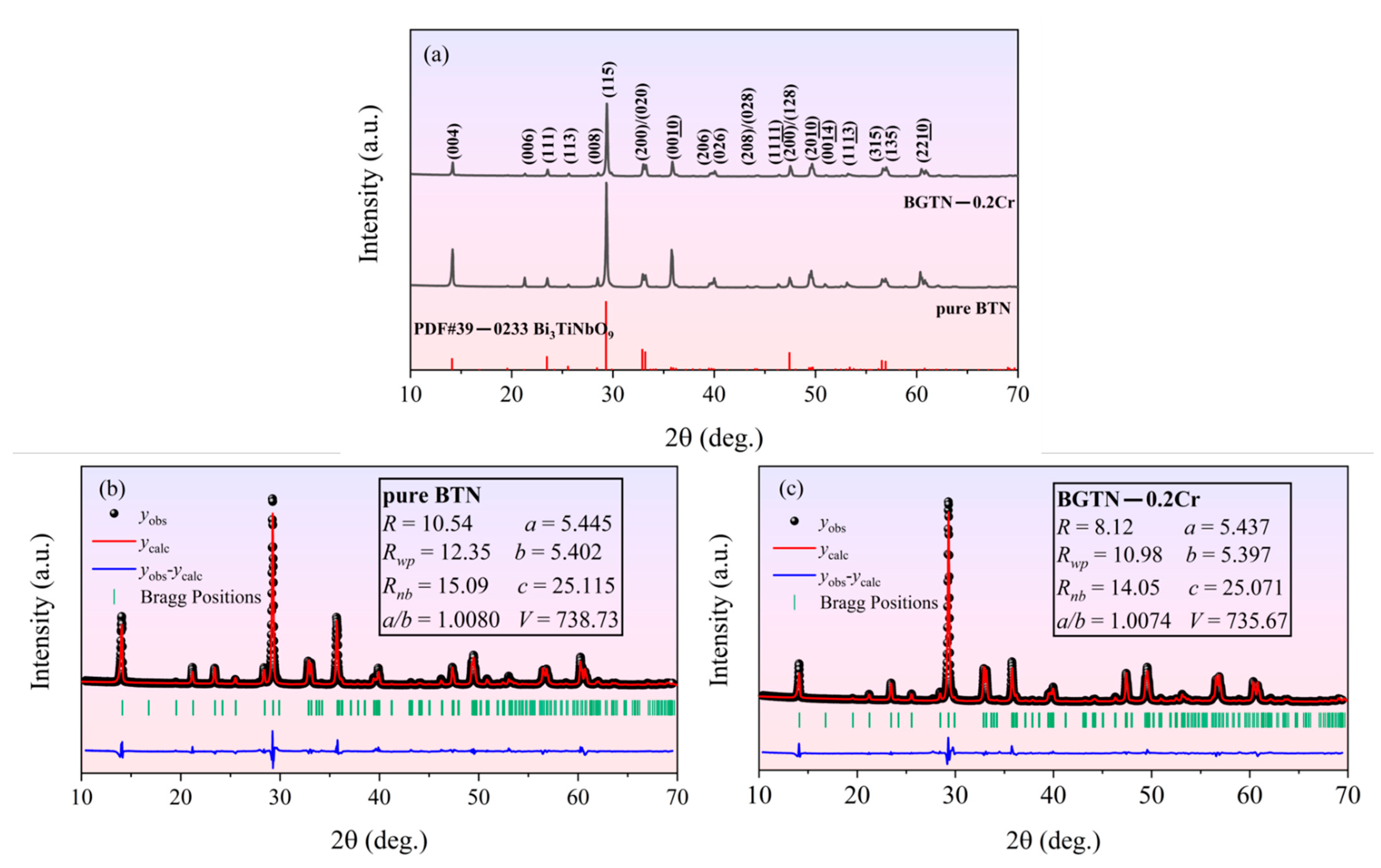
Figure 1. XRD analysis of the sintered ceramics: (a) observed XRD patterns of the pure BTN ceramic and the BGTN−0.2Cr ceramic; (b) Rietveld XRD refinement of the pure BTN ceramic; (c) Rietveld XRD refinement of the BGTN−0.2Cr ceramic.
Materials 14 05598 g001
Figure 2. SEM and EDS analysis of the BGTN−0.2Cr ceramic, focused on its thermal-etched surface (the grain size was determined using the intercept procedure on the basis of the SEM image).
Materials 14 05598 g002
Figure 3. Electrical conduction spectroscopy of the BGTN−0.2Cr ceramic at high temperature: (a) frequency dependence of the total conductivity; (b) relationship between ac conductivity and angular frequency; (c) values of the frequency index factor n calculated by the general Jonscher’s theory; (d) Arrhenius fitting of the plots of lnσdc and lnωp vs. 1000/T.
Materials 14 05598 g003
Figure 4. Lower limit frequency (fLL) of the BGTN−0.2Cr ceramic as a function of temperature.
Materials 14 05598 g004
Figure 5. Electrical impedance spectroscopy of the BGTN−0.2Cr ceramic at high temperature: (a) Z′; (b) −Z″; (c) −Z″ vs. Z′ (inset shows the impedance curve measured below 550 °C); (d) fitting for the Nyquist plot at 600 °C.
Materials 14 05598 g005
Figure 6. Temperature dependence of Rg and Rgb of the BGTN−0.2Cr ceramic (inset shows the Arrhenius fitting of the plots of resistivity vs. temperature).
Materials 14 05598 g006
Figure 7. Electrical modulus spectroscopy of the BGTN−0.2Cr ceramic at high temperature: (a) −M′; (b) M″; (c) M″/Mmax; (d) temperature dependence of β.
Materials 14 05598 g007
Figure 8. Comparison between Z″/Zmax peak and M″/Mmax peak for the BGTN−0.2Cr ceramic (inset shows the Arrhenius fitting of the plots of relaxation time vs. temperature).
Materials 14 05598 g008
Figure 9. Electromechanical resonance spectroscopy of the BGTN−0.2Cr ceramic at room temperature.
Materials 14 05598 g009
Publisher’s Note: MDPI stays neutral with regard to jurisdictional claims in published maps and institutional affiliations.