
Mechanical Behavior and Healing Efficiency of Microcapsule-Based Cemented Coral Sand under Various Water Environments


Abstract
:1. Introduction
2. Materials and Test Procedures
2.1. Material
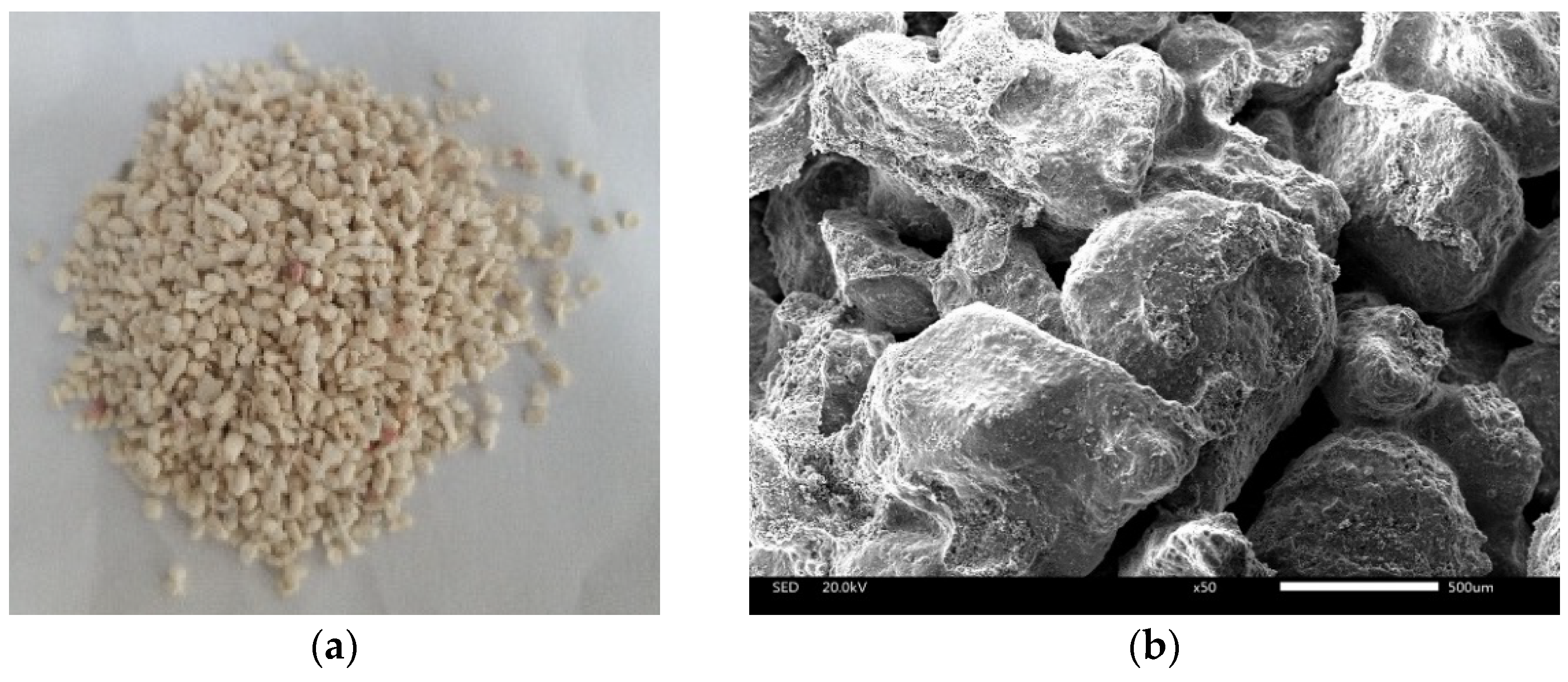
2.2. Microcapsules
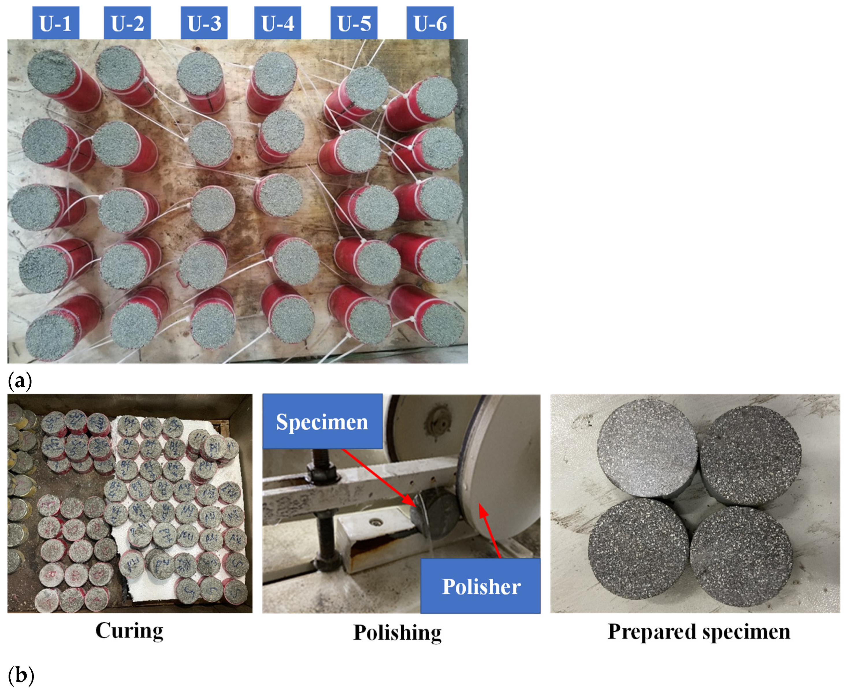
2.3. Specimen Preparation
2.4. Test Procedures
2.4.1. Uniaxial Compressive Test
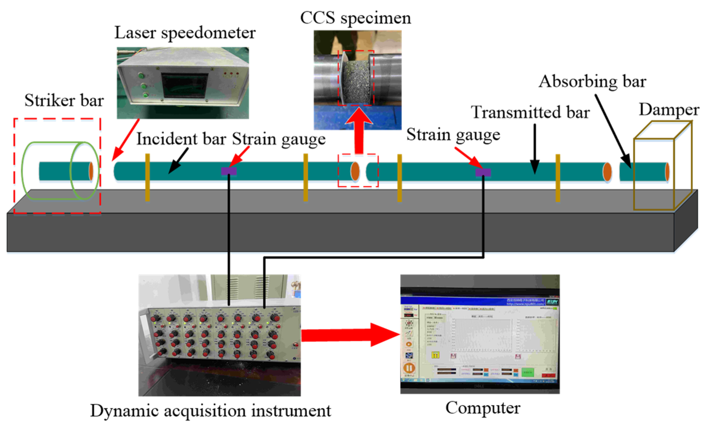
2.4.2. SHPB Test
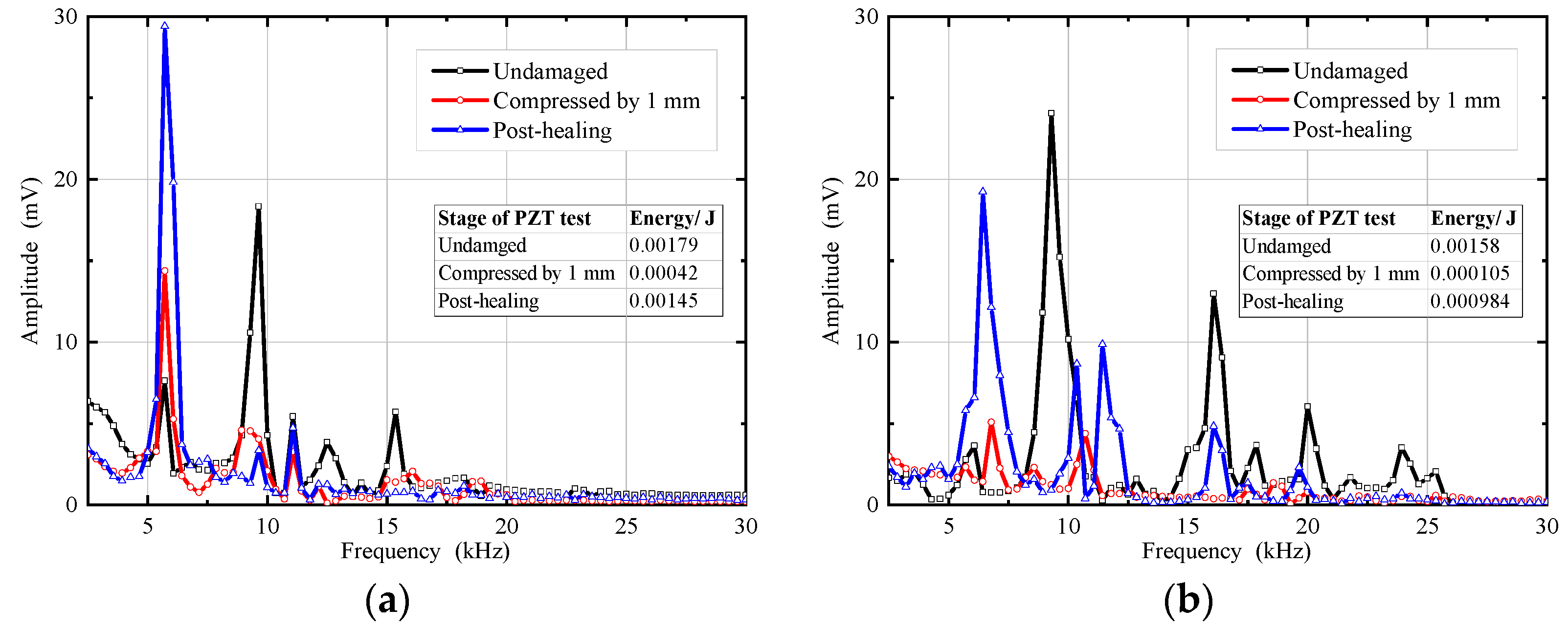
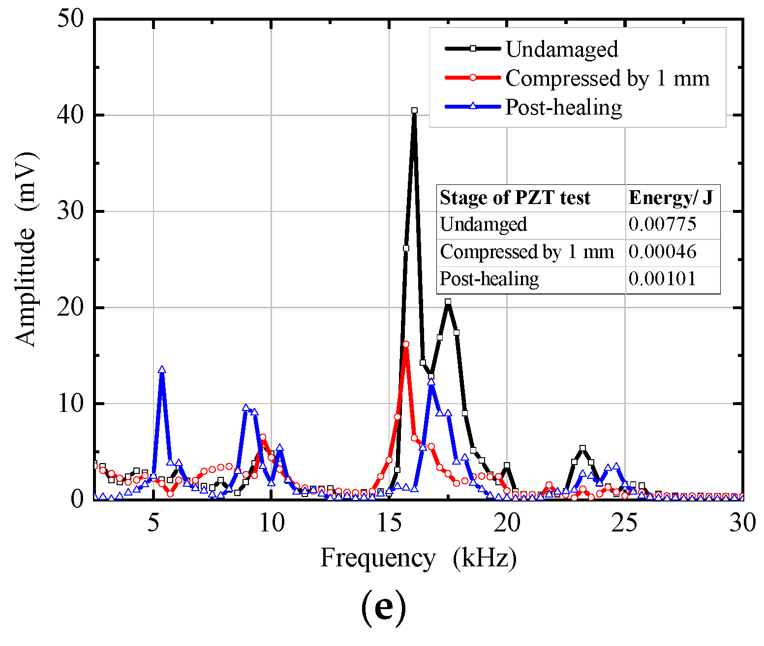
2.5. PZT Test
3. Mechanical Properties of Microcapsule-Based CCS
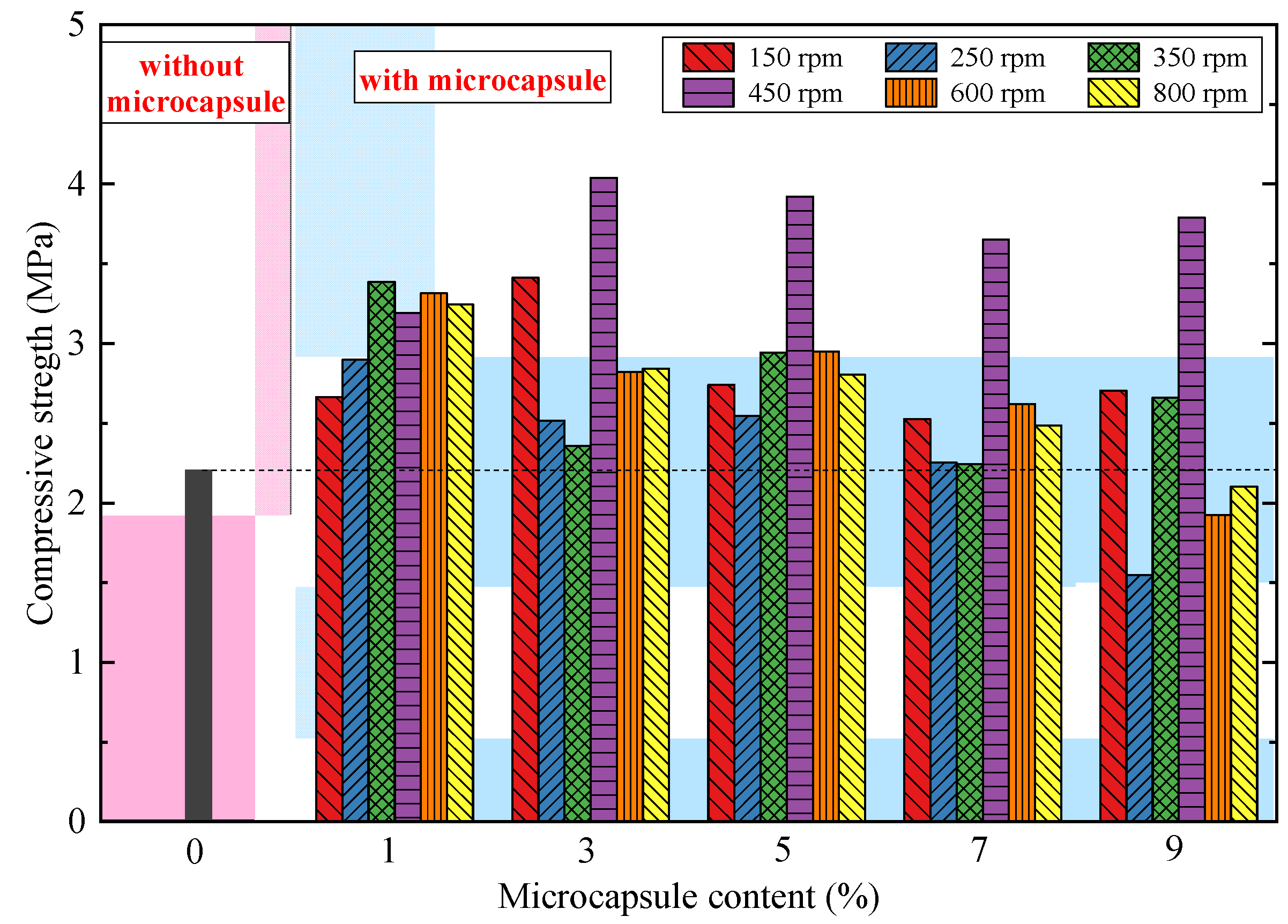
3.1. Uniaxial Compressive Strength (UCS)
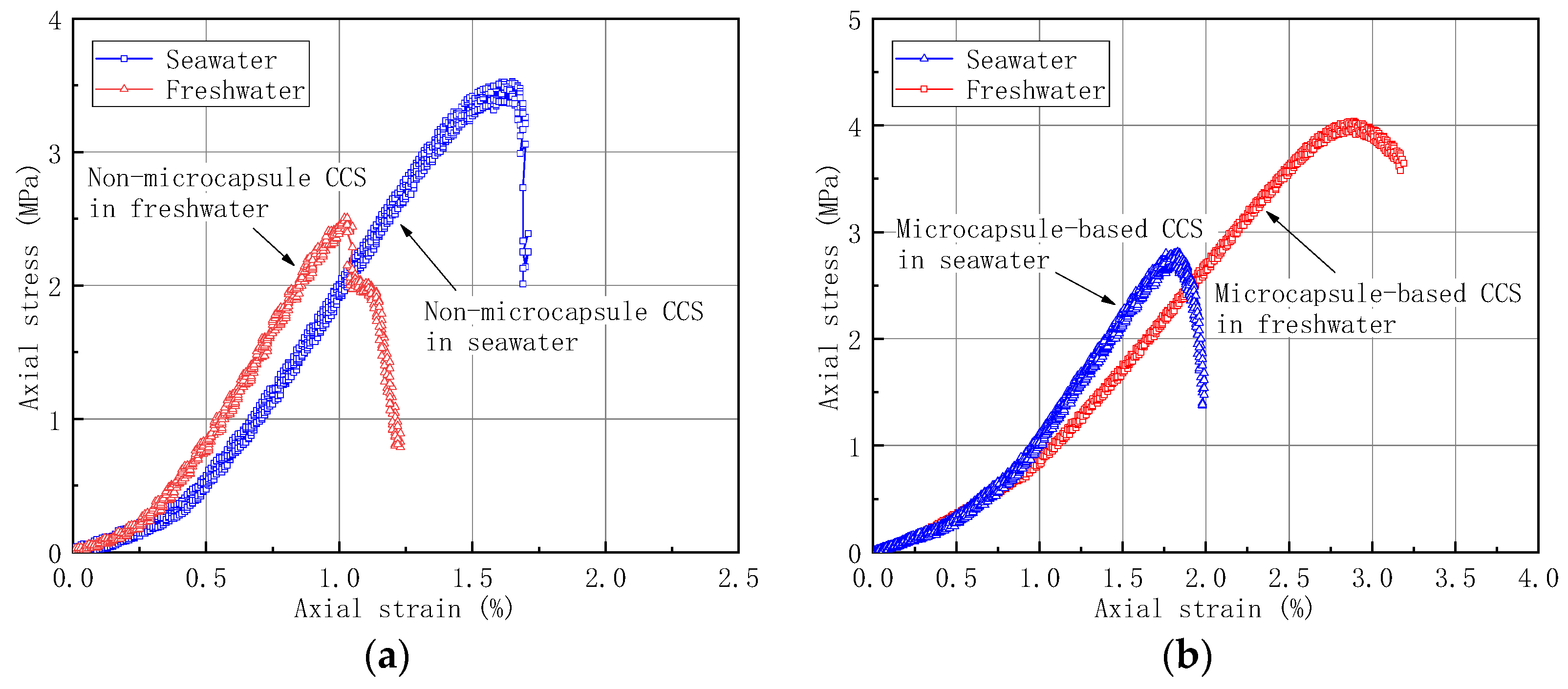
3.2. Comparisons of Seawater and Freshwater
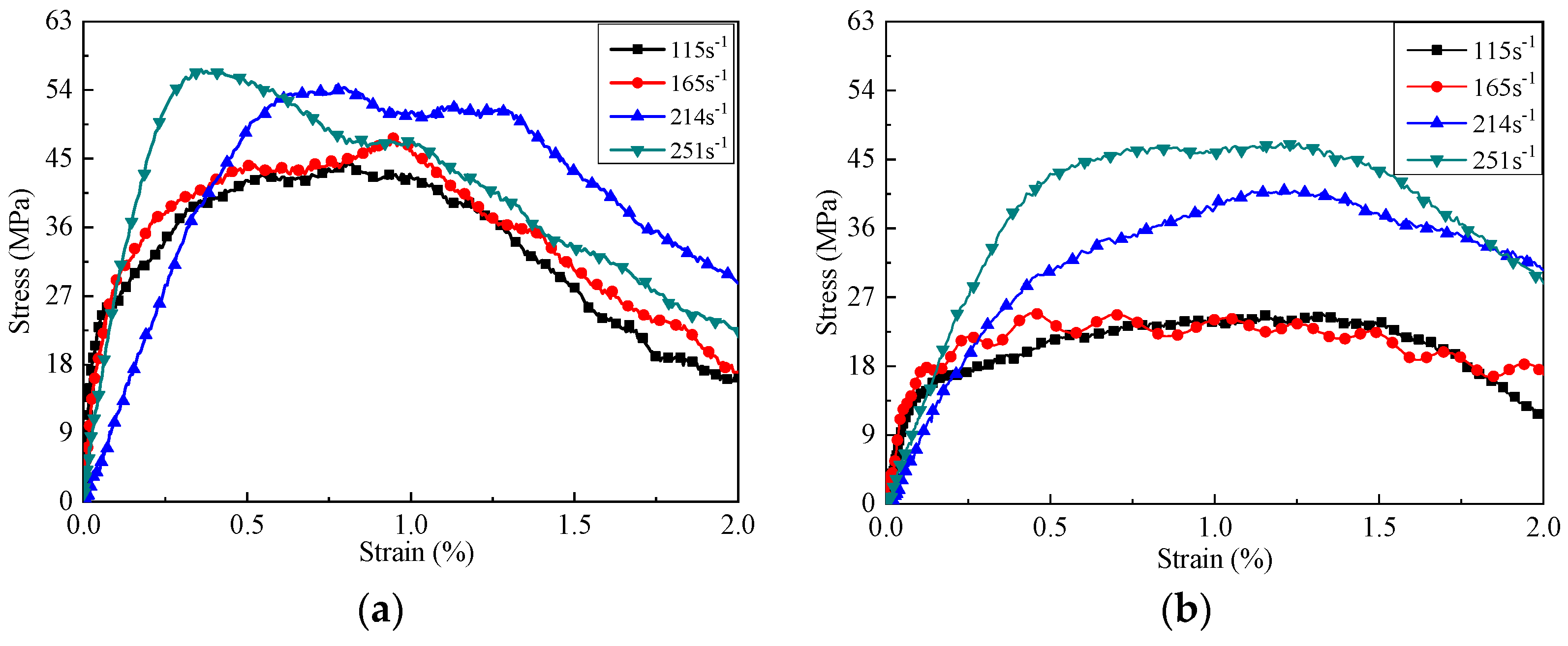
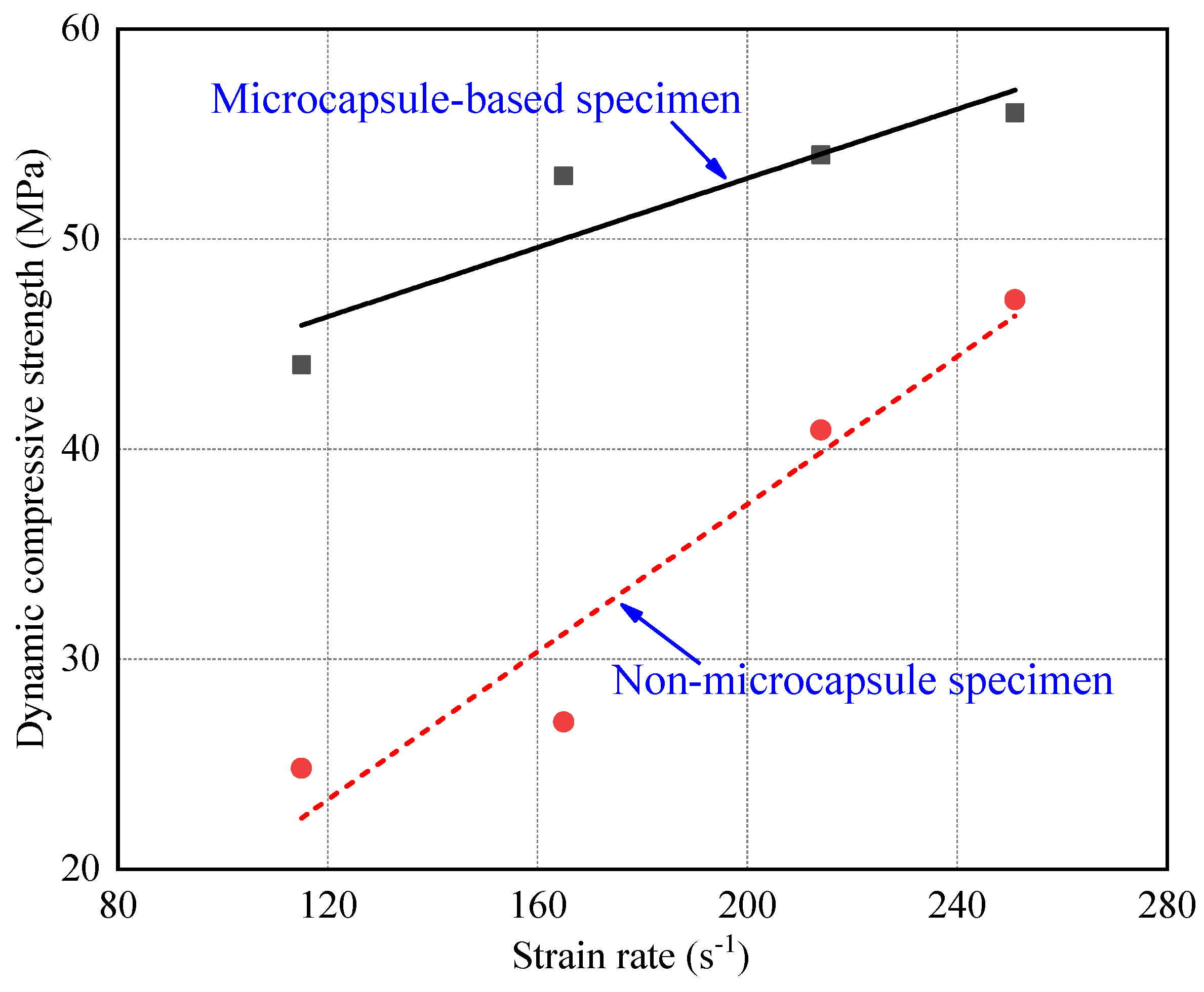
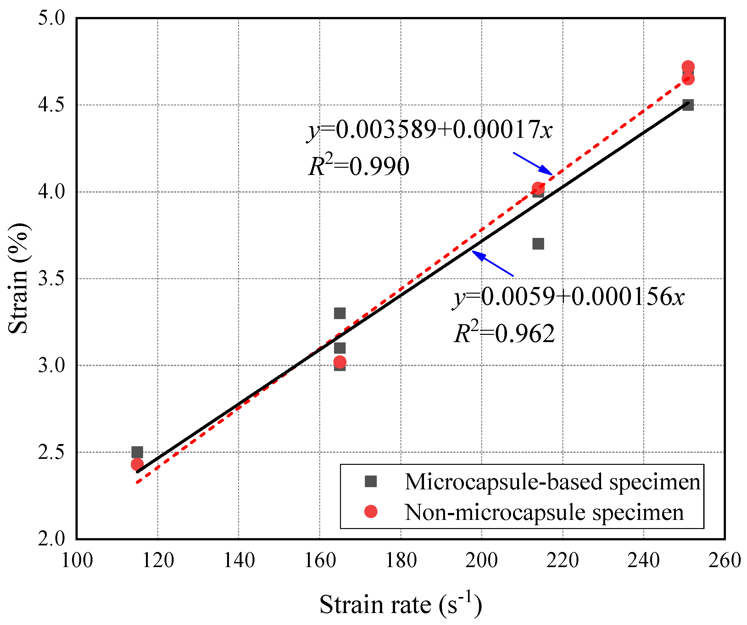
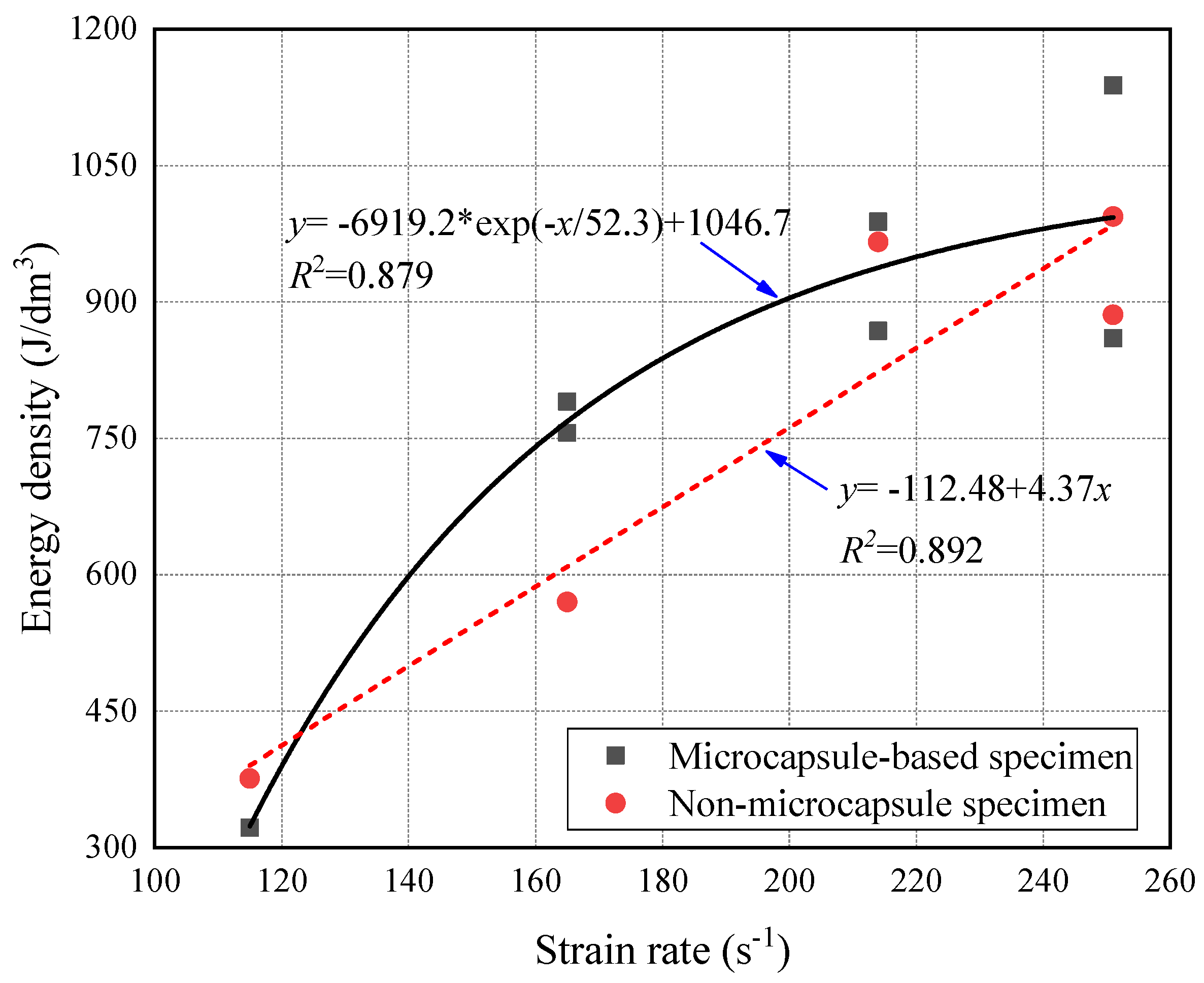
3.3. SHPB Test Results
4. Healing Efficiency of Microcapsule in CCS
4.1. Healing Efficiency in Freshwater and Seawater Environment
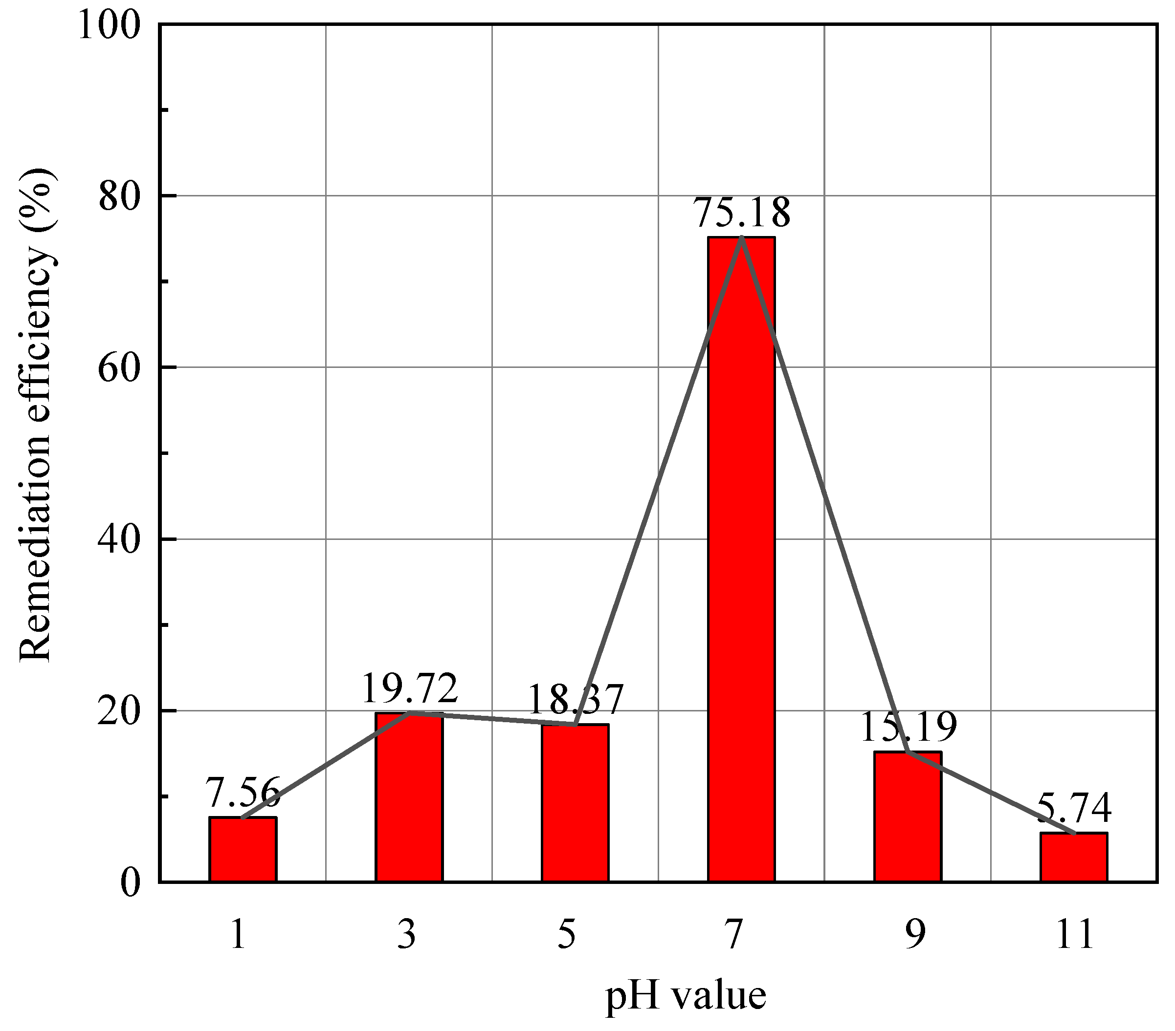
4.2. Healing Efficiency in Solution of Various pH
5. Conclusions
- The microcapsule in the CCS could improve the initial strength of the specimens by 45–83%. The optimal mixed ratio of microcapsule was 3% (i.e., mass ratio to the cement) under the synthesized rotating speed of 450 rmp. The seawater environment would decrease the compressive strength of the microcapsule-based CCS.
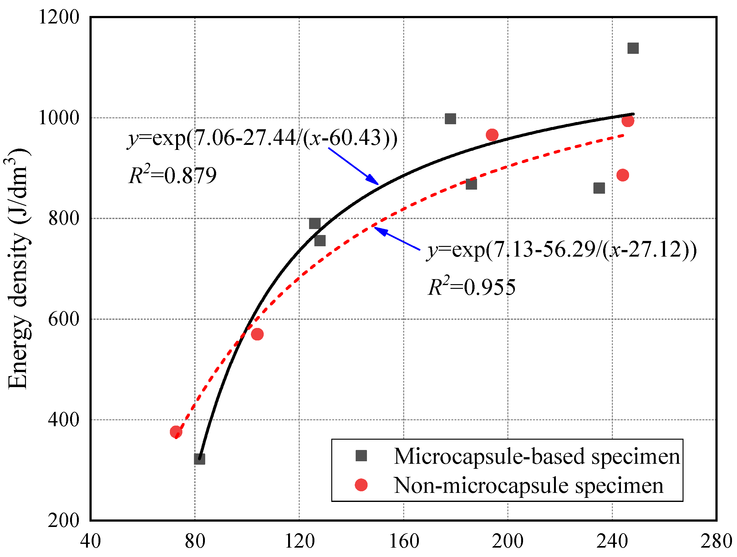
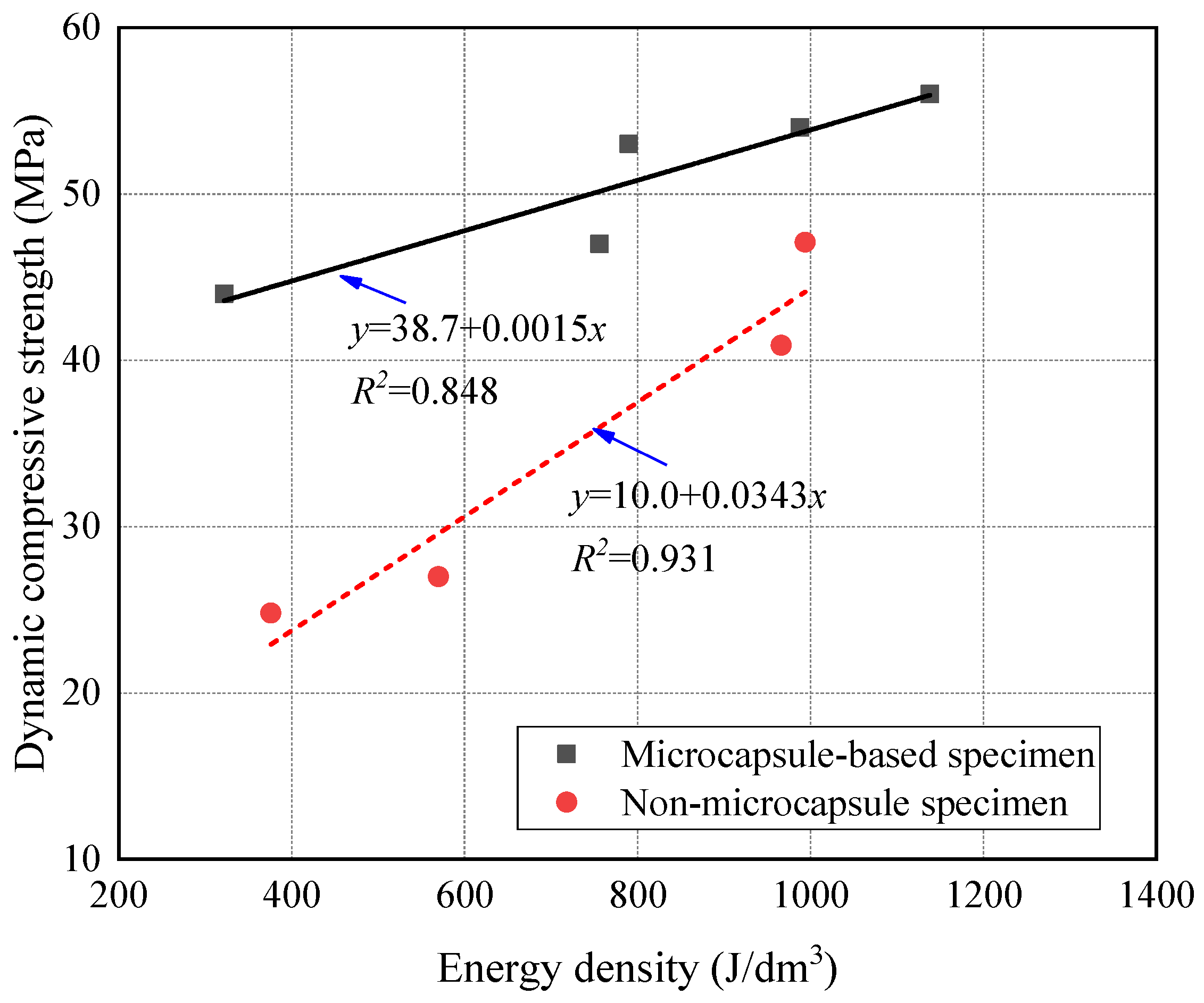
- The SHPB impact tests indicated that the mix of microcapsules improved the initial dynamic compressive strength of the CCS. The absorbed energy by microcapsules was dissipated in the damage and deformation of the CCS specimens and the heat change of microcapsules. The microcapsule would reduce the dependence of the strength of the specimen on the incident energy and reduce the growth rate of strength with the energy density.
- According to the PZT test results, the healing efficiency of microcapsules in freshwater and seawater was 75% and 59.56%, respectively. The acid–base environment of the surrounding water of microcapsule-based CCS would inhibit the healing effect of microcapsules. The healing efficiency in acid–base water ranged from 5.74% to 19.72, which was especially low in the peracid and peralkalic water environment.
Author Contributions
Funding
Data Availability Statement
Conflicts of Interest
References
- Qin, Y.; Meng, Q.S.; Wang, R.; Hu, S.Q.; Zhang, Y.T. Model experimental research on uplift single pile in calcareous sand of South China Sea. Mar. Georesour. Geotechnol. 2017, 35, 653–660. [Google Scholar]
- Xu, D.S.; Huang, M.; Zhou, Y. One-dimensional compression behavior of calcareous sand and marine clay mixtures. Int. J. Geomech. 2020, 20, 04020137. [Google Scholar] [CrossRef]
- Xu, D.S.; Chen, W.; Fan, X.C. Experimental investigation of particle size effect on the self-healing performance of microcapsule for cemented coral sand. Constr. Build. Mater. 2020, 256, 119343. [Google Scholar] [CrossRef]
- Qin, Y.; Yao, T.; Wang, R.; Zhu, C.Q.; Meng, Q.S. Particle breakage-based analysis on deformation law of calcareous sediments under high-pressure consolidation. Rock Soil Mech. 2014, 35, 3123–3128. [Google Scholar]
- Xu, D.S.; Tang, Z.Y.; Zhang, L. Interpretation of coarse effect in simple shear behavior of binary sand-gravel mixture by DEM with authentic particle shape. Constr. Build. Mater. 2019, 195, 292–304. [Google Scholar] [CrossRef]
- Chen, M.Y.; Geng, J.G.; Xiong, H.C.; Shang, T.; Xue, C.; Abbas, M. Effect of curing on mechanical properties of cement-stabilized coral sand in marine environment. Adv. Mater. Sci. Eng. 2020, 2020, 4678376. [Google Scholar] [CrossRef]
- Chu, S.H.; Yao, J.J. A strength model for concrete made with marine dredged sediment. J. Clean. Prod. 2020, 274, 122673. [Google Scholar] [CrossRef]
- Xu, D.S.; Zhang, Z.J.; Qin, Y.; Yang, Y. Effect of particle size on the failure behavior of cemented coral sand under impact loading. Soil Dyn. Earthq. Eng. 2021, 149, 106884. [Google Scholar] [CrossRef]
- Lívia, S.; Abir, A.T. Microfluidic fabrication of microcapsules tailored for selfhealing in cementitious materials. Constr. Build. Mater. 2018, 184, 713–722. [Google Scholar]
- Du, W.; Yu, J.Y.; Gu, Y.; Li, Y.; Han, X.B.; Liu, Q.T. Preparation and application of microcapsules containing toluene-di-isocyanate for self-healing of concrete. Constr. Build. Mater. 2019, 202, 762–769. [Google Scholar] [CrossRef]
- Mariano, M.; Bruna, C.L.; Marcio, S.C. Microfluidic production of aqueous suspensions of gellan-based microcapsules containing hydrophobic compounds. Chem. Eng. Sci. 2020, 211, 115314. [Google Scholar]
- Yuan, X.H.; Chen, Y.Q.; Zhang, Q.; Liu., Y.Q. Preparation and performance of self-healing epoxy resin matrix composites using microcapsules. J. Jiangsu Univ. 2017, 38, 461–465, 471. [Google Scholar]
- Wang, Y.J.; Pham, D.T.; Ji, C.Q. Self-healing composites: A review. Cogent Eng. 2015, 2, 1075686. [Google Scholar] [CrossRef] [Green Version]
- Wan, J.; Han, C. Experimental study and evaluation of self-healing concrete with encapsulated glue. New Build. Mater. 2014, 41, 40–42. [Google Scholar]
- Chen, C.; McDowell, G.R.; Rui., R. Discrete element modelling of geogrids with square and triangular apertures. Geomech. Eng. 2018, 16, 495–501. [Google Scholar]
- Dry, C.M.; Corsaw, M.J.T. A time-release technique for corrosion prevention. Cem. Concr. Res. 1998, 28, 1133–1140. [Google Scholar] [CrossRef]
- Liu, S.K.; Zeynep, B.B.; Zhu, J.Y.; Raissa, D.F. Evaluation of self-healing of internal cracks in biomimetic mortar using coda wave interferometry. Cem. Concr. Res. 2016, 83, 70–78. [Google Scholar] [CrossRef]
- Qian, C.X.; Chen, H.C.; Ren, L.F.; Luo, M. Self-healing of early age cracks in cement-based materials by mineralization of carbonic anhydrase microorganism. Front. Microbiol. 2015, 6, 1125. [Google Scholar] [CrossRef] [Green Version]
- Aghamirzadeh, G.H.R.; Khalili, S.M.R.; Eslami-Farsani, R.; Saeedi, A. Experimental investigation on the smart self-healing composites based on the short hollow glass fibers and shape memory alloy strips. Polym. Compos. 2018, 40, 1883–1889. [Google Scholar] [CrossRef]
- Srivastava, V.; Gupta, M. Approach to self-healing in Metal matrix Composites: A review. Mater. Today 2018, 5, 19703–19713. [Google Scholar] [CrossRef]
- Cohades, A.; Hostettler, N.; Pauchard, M.; Plummer, C.J.G.; Michauda, V. Stitched shape memory alloy wires enhance damage recovery in self-healing fibre-reinforced polymer composites. Compos. Sci. Technol. 2018, 161, 22–31. [Google Scholar] [CrossRef] [Green Version]
- Tang, G.H.; John, K.L.H.; Dong, G.N.; Hua., M. Fabrication self-recovery bulge textures on TiNi shape memory alloy and its tribological properties in lubricated sliding. Tribol. Int. 2016, 96, 11–22. [Google Scholar] [CrossRef]
- White, S.R.; Scottos, N.R.; Geubelle, P.H.; Moore, J.S.; Kessler, M.R.; Sriram, S.R.; Brown, E.N.; Viswanathan., S. Autonomic healing of polymer composites. Nature 2001, 409, 794–797. [Google Scholar] [CrossRef] [PubMed]
- Rule, J.D.; Sottos, N.R.; White., S.R. Effect of microcapsule size on the performance of self-healing polymers. Polymer 2007, 48, 3520–3529. [Google Scholar] [CrossRef]
- Tan, P.S.; Somashekar, A.A.; Casari, P.; Bhattacharyya, D. Healing efficiency characterization of self-repairing polymer composites based on damage continuum mechanics. Compos. Struct. 2019, 208, 367–376. [Google Scholar] [CrossRef]
- Li, L.; Yuan, L.; Liang, G.Z.; Xie, J.Q. Effects of processing parameters on physical properties of poly (urea-formaldehyde) microcapsules of epoxy resin. Acta Mater. Compos. Sin. 2006, 23, 51–57. [Google Scholar] [CrossRef]
- Ou, J.P.; Kuang, Y.C. Experiments and analysis of concrete material with crack self-repairing performance using embedded capsules filled with adhesive. Acta Mech. Solida Sin. 2004, 25, 320–324. [Google Scholar]
- Yuan, Y.C.; Rong, M.Z.; Zhang., M.Q. Preparation and characterization of poly (melamine-formaldehyde) walled microcapsules containing epoxy. Acta Polym. Sin. 2008, 5, 472–480. [Google Scholar] [CrossRef]
- Cao, V.D.; Pilehvar, S.; Salas-Bringas, C.; Szczotok, A.M.; Valentini, L.; Carmona, M.; Rodriguez, J.F.; Kjøniksen., A.-L. Influence of microcapsule size and shell polarity on thermal and mechanical properties of thermoregulating geopolymer concrete for passive building applications. Energy Convers. Manag. 2018, 164, 198–209. [Google Scholar] [CrossRef]
- Wei, H.Z.; Xu, D.S.; Meng, Q.S. A newly designed fiber-optic based earth pressure transducer with adjustable measurement range. Sensors 2018, 18, 932. [Google Scholar] [CrossRef] [Green Version]
- Kucewicz, M.; Baranowski, P.; Małachowski, J. Dolomite fracture modeling using the Johnson-Holmquist concrete material model: Parameter determination and validation. J. Rock Mech. Geotech. Eng. 2021, 13, 335–350. [Google Scholar] [CrossRef]
- Tenreiro, A.F.G.; Silva, C.M.; Lopes, A.M.; Nunes, P.D.P.; Carbas, R.J.C.; da Silva, L.F.M. Design of a new pneumatic impact actuator of a Split Hopkinson Pressure Bar (SHPB) setup for tensile and compression testing of structural adhesives. Mech. Mach. Theory 2021, 159, 104289. [Google Scholar] [CrossRef]
- Liu, P.; Hu, D.; Wu, Q.K.; Liu, X.M. Sensitivity and uncertainty analysis of interfacial effect in SHPB tests for concrete-like materials. Constr. Build. Mater. 2018, 163, 414–427. [Google Scholar] [CrossRef]
- Kolsky, H. An investigation of the mechanical properties of materials at very high rates of loading. Proc. Phys. Society Sect. B 1949, 62, 676–700. [Google Scholar] [CrossRef]
- Ross, C.A.; Tedesco, J.W.; Kuennen, S.T. Effects of strain rate on concrete strength. Mater. J. 1995, 92, 37–47. [Google Scholar]
- Ross, C.A. Strain-rate-dependent constitutive equations for concrete. J. Press. Vessel. Technol. 1998, 120, 398–405. [Google Scholar]
- Xu, Z.J.; Ding, X.Y.; Zhang, W.Q.; Huang, F.L. A novel method in dynamic shear testing of bulk materials using the traditional SHPB technique. Int. J. Impact Eng. 2017, 101, 90–104. [Google Scholar] [CrossRef]
- Al-Salloum, Y.; Almusallam, T.; Ibrahim, S.M.; Abbas, H.; Alsayed, S. Rate dependent behavior and modeling of concrete based on SHPB experiments. Cem. Concr. Compos. 2015, 55, 34–44. [Google Scholar] [CrossRef]
- Quintana, C.; Rodríguez, C.; Belzunce, F.J.; Caballero, A.C.; Baudín, C. Ceramic materials characterization using miniature mechanical tests: Comparison between B3B and SPT tests. J. Eur. Ceram. Soc. 2019, 39, 4113–4121. [Google Scholar] [CrossRef]
- Wang, Y.; Li, X.D.; Li, J.H.; Wang, Q.; Xu, B.; Deng, J. Debonding damage detection of the CFRP-concrete interface based on piezoelectric ceramics by the wave-based method. Constr. Build. Mater. 2019, 210, 514–524. [Google Scholar] [CrossRef]
- Liu, Q.; Zhou, W.; Ding, J.; Xiao, M.; Yu, Z.J.; Xu, H.; Mao, W.G.; Pei, Y.M.; Li, F.X.; Feng, X.; et al. Study of mechanical-magnetic and electromagnetic properties of PZT/Ni film systems by a novel bulge technique. J. Magn. Magn. Mater. 2017, 423, 90–97. [Google Scholar] [CrossRef]
- Ji, Y.L.; Pel, L.; Sun, Z.P. The microstructure development during bleeding of cement paste: An NMR study. Cem. Concr. Res. 2019, 125, 105866. [Google Scholar] [CrossRef]
- Wu, J.Y.; Feng, M.M.; Ni, X.Y.; Mao, X.B.; Chen, Z.Q.; Han, G.S. Aggregate gradation effects on dilatancy behavior and acoustic characteristic of cemented rock fill. Ultrasonics 2019, 92, 79–92. [Google Scholar] [CrossRef] [PubMed]
- Assi, L.; Soltangharaei, V.; Anay, R.; Ziehl, P.; Matta, F. Unsupervised and supervised pattern recognition of acoustic emission signals during early hydration of Portland cement paste. Cem. Concr. Res. 2018, 103, 216–225. [Google Scholar] [CrossRef]
- Xu, D.S.; Liu, H.B.; Luo, W.L. Development of a novel settlement monitoring system using fiber-optic liquid-level transducers with automatic temperature compensation. IEEE Trans. Instrum. Meas. 2018, 67, 2214–2222. [Google Scholar] [CrossRef]
- Cao, S.; Yilmaz, E.; Yin, Z.Y.; Xue, G.; Song, W.D.; Sun, L.J. CT scanning of internal crack mechanism and strength behavior of cement-fiber-tailings matrix composites. Cem. Concr. Compos. 2021, 116, 103865. [Google Scholar] [CrossRef]
- Xue, G.; Yilmaz, E.; Song, W.; Cao., S. Analysis of internal structure behavior of fiber reinforced cement-tailings matrix composites through X-ray computed tomography. Compos. Part B Eng. 2019, 175, 107091. [Google Scholar] [CrossRef]
- Shen, J.H.; Xu, D.S.; Liu, Z.W.; Wei, H.Z. Effect of particle characteristics stress on the mechanical properties of cement mortar with coral sand. Constr. Build. Mater. 2020, 260, 119836138. [Google Scholar] [CrossRef]
- Kim, J.S.; Chung, S.Y.; Stephan, D.; Han, T.S. Issues on characterization of cement paste microstructures from μ-CT and virtual experiment framework for evaluating mechanical properties. Constr. Build. Mater. 2019, 202, 82–102. [Google Scholar] [CrossRef]
- ASTM D1141-98(2013). Standard Practice for the Preparation of Substitute Ocean Water; ASTM International: West Conshohocken, PA, USA, 2013. [Google Scholar]
- Pajak, M.; Baranowski, P.; Janiszewski, J.; Kucewicz, M.; Mazurkiewicz, L.; Łaźniewska-Piekarczyk, B. Experimental testing and 3D meso-scale numerical simulations of SCC subjected to high compression strain rates. Constr. Build. Mater. 2021, 302, 124379. [Google Scholar] [CrossRef]


| 0.25–0.5 (mm) | 0.5–1 (mm) | d10 (mm) | d50 (mm) | d90 (mm) | Cu | Cc |
|---|---|---|---|---|---|---|
| 43.62% | 56.38% | 0.29 | 0.40 | 0.61 | 2.10 | 0.90 |
| NaCl (g/L) | MaCl2 (g/L) | Na2SO4 (g/L) | CaCl2 (g/L) | H2O (L) |
|---|---|---|---|---|
| 24.53 | 5.20 | 4.09 | 1.16 | 1 |
| Usage | Reagent | Purity Specifications |
|---|---|---|
| Core material | Epoxy Resin (E-51) | Technical pure |
| Wall material | Carbamide | Analytically pure |
| Methanal | Analytically pure/ 37% aqueous solution | |
| pH Regulator | Triethanolamine | Analytically pure |
| Anhydrous sodium carbonate | Analytically pure | |
| Emulsifier | Sodium dodecyl benzene sulfonate | Analytically pure |
| Polyvinyl alcohol (PVA) | Analytically pure | |
| Defoamer | N-caprylic alcohol | Analytically pure |
| Acid catalyst | Ammonium chloride | Analytically pure |
| Curing agent | Resorcin | Analytically pure |
| Test | Specimen ID | Pre-Treatment | Microcapsule Content (%) | Rotating Speed (rpm) | Mixing Water |
|---|---|---|---|---|---|
| Uniaxial compressive test | U-1 | No | 0 | - | Seawater |
| U-2 | 0 | - | Freshwater | ||
| U-3 | 1 | 150–800 | Freshwater | ||
| U-4 | 3 | 150–800 | Freshwater | ||
| U-5 | 5 | 150–800 | Freshwater | ||
| U-6 | 7 | 150–800 | Freshwater | ||
| U-7 | 9 | 150–800 | Freshwater | ||
| U-8 | 3 | 450 | Seawater | ||
| SHPB test | S-1 | No | 0 | - | Freshwater |
| S-2 | 3 | 450 | Freshwater | ||
| S-3 | 3 | 450 | Seawater | ||
| PZT test | P-1 | Yes | 3 | 450 | Seawater |
| P-2 (pH = 1) | Freshwater | ||||
| P-3 (pH = 3) | Freshwater | ||||
| P-4 (pH = 5) | Freshwater | ||||
| P-5 (pH = 7) | Freshwater | ||||
| P-6 (pH = 9) | Freshwater | ||||
| P-7 (pH = 11) | Freshwater |
| Parameter | Value |
|---|---|
| Launch pressure (Pl) | 0.6, 0.8, 1.0, 1.2 Bar |
| Wave velocity of impact bar (C0) | 5000 m/s |
| Elastic modulus of impact bar (E0) | 210,000 MPa |
| Diameter and length of bullet (Db and Lb) | 60 mm and 50 cm |
| Length of incident bar and transmission bar (Li and Lt) | 2.8 m |
| Diameter of incident bar and transmission bar (Di and Dt) | 60 mm |
| Frequency of dynamic acquisition instrument (F) | 2.5 MHz |
| Amplification factor of dynamic acquisition instrument (Fa) | 100 |
| Bridge voltage (Vb) | 2 V |
| Strain Rate | 115 s−1 | 165 s−1 | 214 s−1 | 251 s−1 |
|---|---|---|---|---|
| With microcapsule |  |  |  | 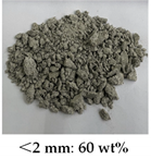 |
| Without microcapsule | 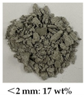 |  | 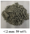 |  |
| Group | pH = 1 | pH = 3 | pH = 5 | pH = 9 | pH = 11 |
|---|---|---|---|---|---|
| Initial wave velocity (m/s) | 1235.03 | 1210.67 | 1220.45 | 1254.99 | 1275.49 |
| Post-damage (m/s) | 943.47 | 886.86 | 994.57 | 875.19 | 821.17 |
| Post-healing (m/s) | 1081.54 | 1120.30 | 1177.25 | 1156.77 | 1031.23 |
| Initial energy (mJ) | 7.7495 | 8.3060 | 6.9290 | 5.7970 | 4.0750 |
| Post-damage energy (mJ) | 0.4569 | 0.2360 | 0.5160 | 0.4360 | 0.6930 |
| Post-healing energy (mJ) | 1.0088 | 1.8280 | 1.6940 | 1.2920 | 0.8870 |
| Healing efficiency (%) | 7.56 | 19.72 | 18.37 | 15.97 | 5.74 |
Publisher’s Note: MDPI stays neutral with regard to jurisdictional claims in published maps and institutional affiliations. |
© 2021 by the authors. Licensee MDPI, Basel, Switzerland. This article is an open access article distributed under the terms and conditions of the Creative Commons Attribution (CC BY) license (https://creativecommons.org/licenses/by/4.0/).
Share and Cite
Qin, Y.; Wang, Q.; Xu, D.; Chen, W. Mechanical Behavior and Healing Efficiency of Microcapsule-Based Cemented Coral Sand under Various Water Environments. Materials 2021, 14, 5571. https://doi.org/10.3390/ma14195571
Qin Y, Wang Q, Xu D, Chen W. Mechanical Behavior and Healing Efficiency of Microcapsule-Based Cemented Coral Sand under Various Water Environments. Materials. 2021; 14(19):5571. https://doi.org/10.3390/ma14195571
Chicago/Turabian StyleQin, Yue, Qiankun Wang, Dongsheng Xu, and Wei Chen. 2021. "Mechanical Behavior and Healing Efficiency of Microcapsule-Based Cemented Coral Sand under Various Water Environments" Materials 14, no. 19: 5571. https://doi.org/10.3390/ma14195571
APA StyleQin, Y., Wang, Q., Xu, D., & Chen, W. (2021). Mechanical Behavior and Healing Efficiency of Microcapsule-Based Cemented Coral Sand under Various Water Environments. Materials, 14(19), 5571. https://doi.org/10.3390/ma14195571