
Manufacturing Technology and Properties of Fe/TaC Metal Matrix Composite Coatings Produced on Medium Carbon Steel Using Laser Processing—Preliminary Study on the Single Laser Tracks


Abstract
:1. Introduction
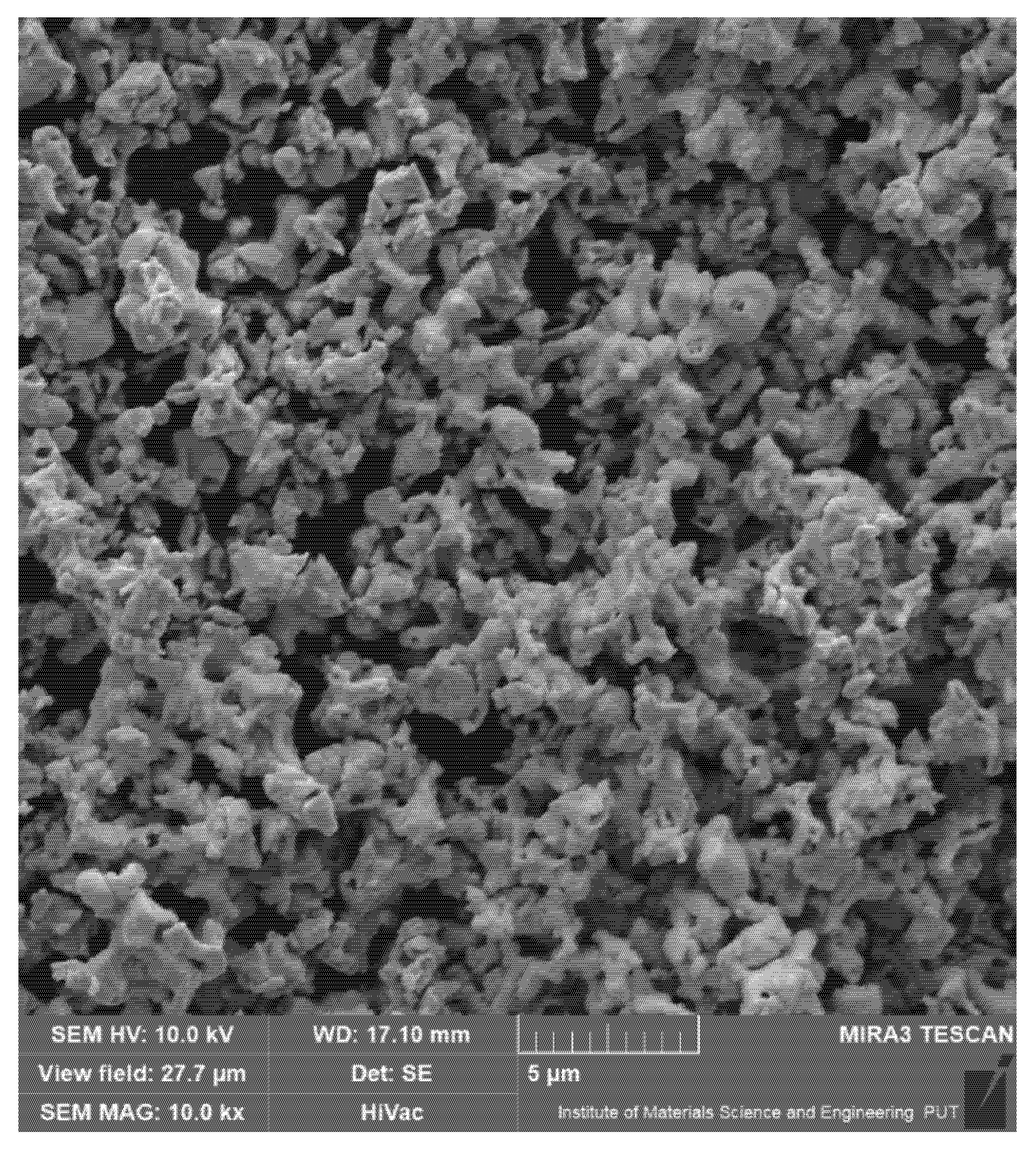
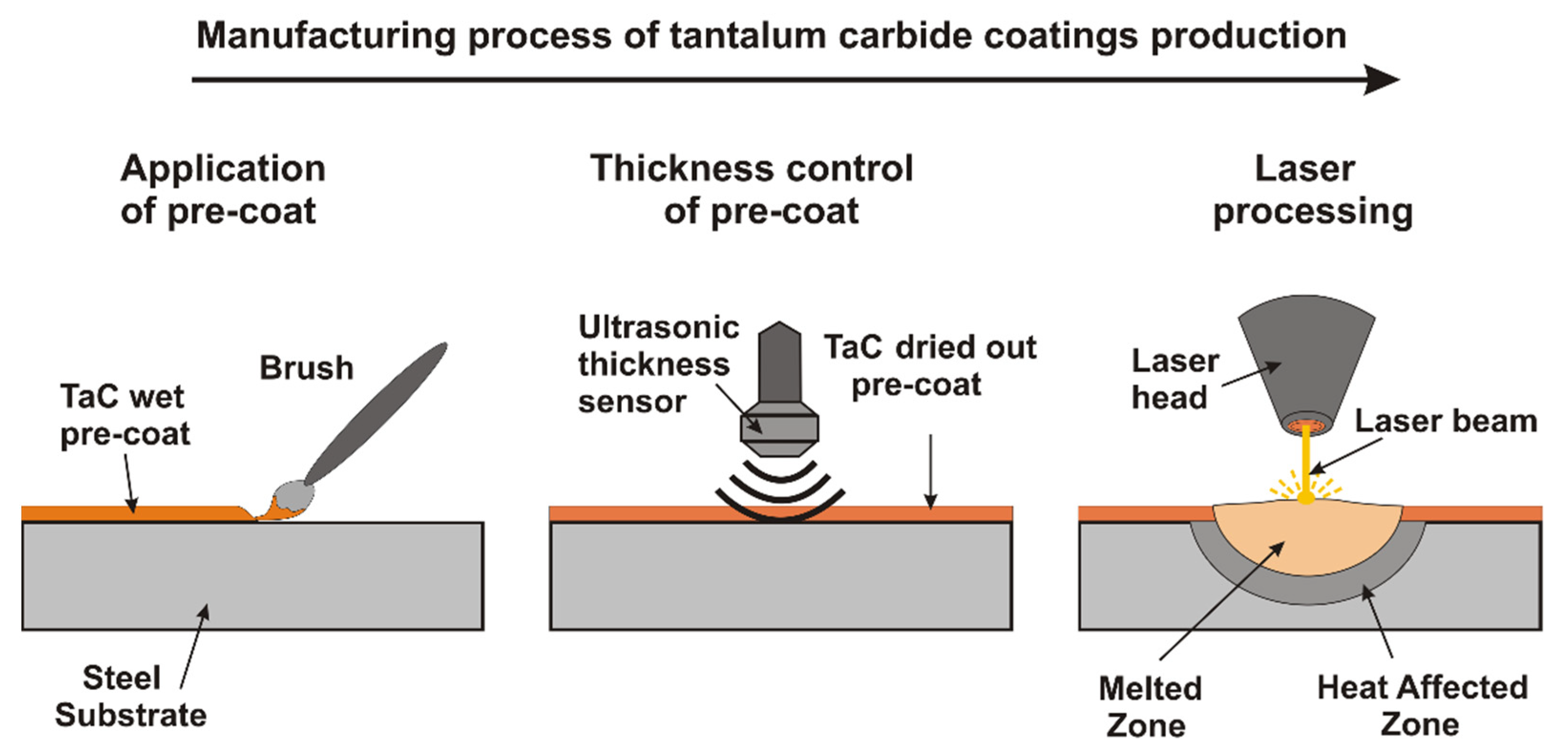
2. Materials and Methods
3. Results
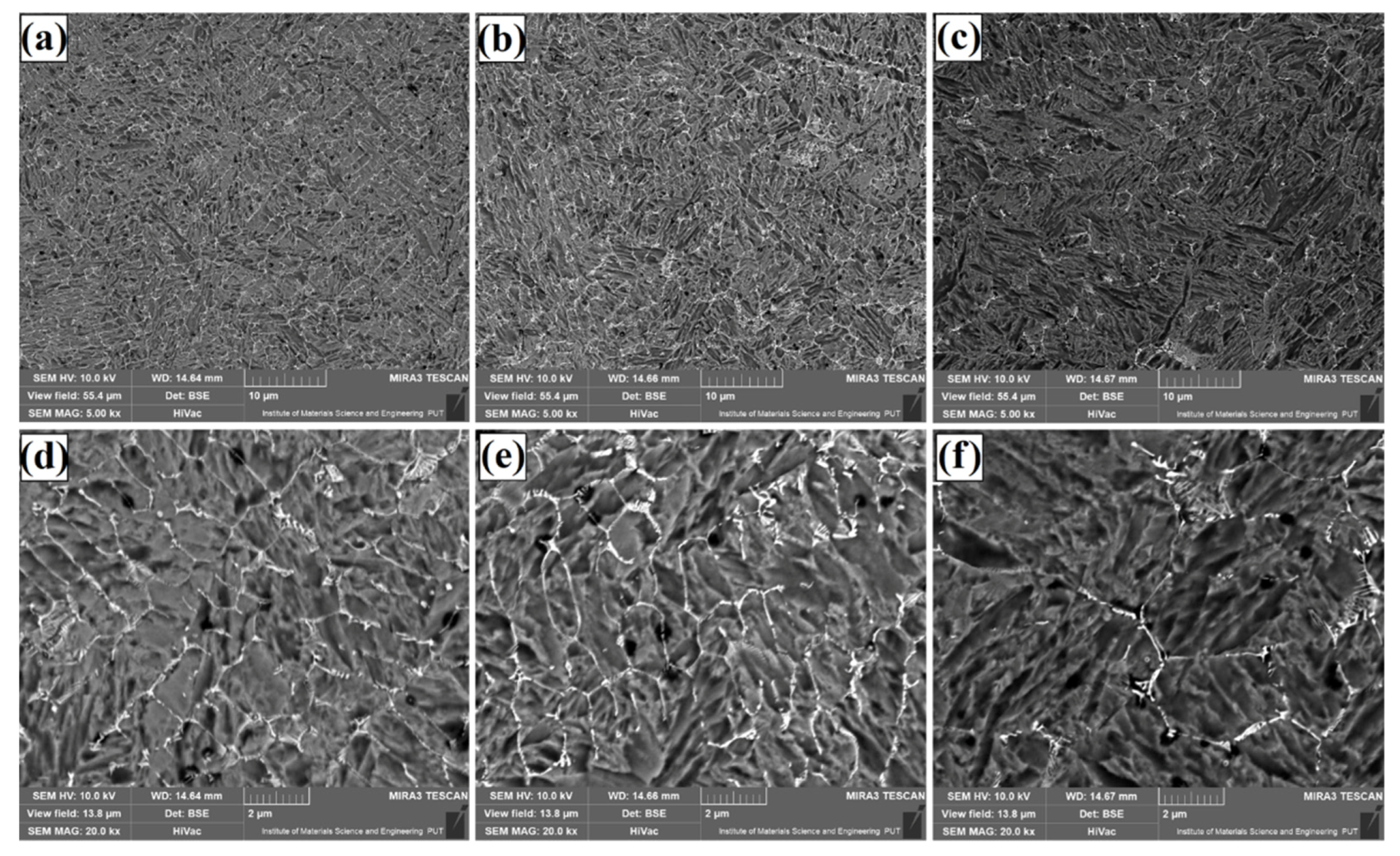
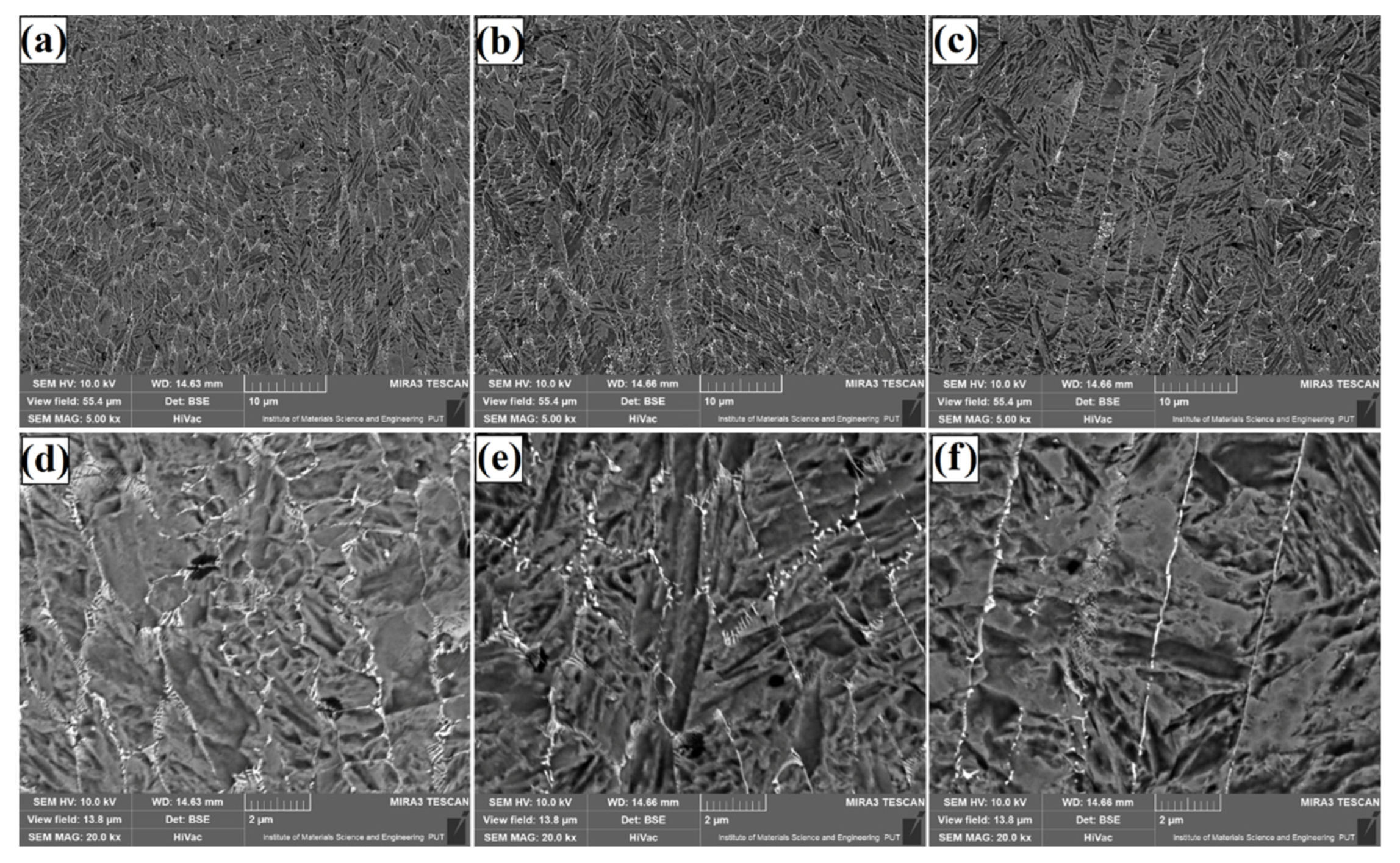
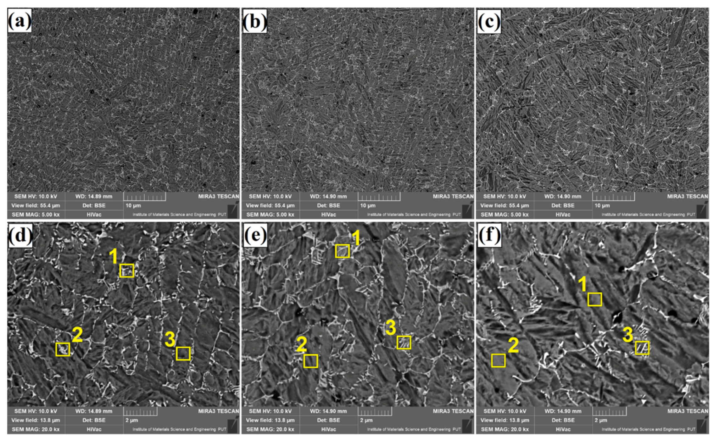
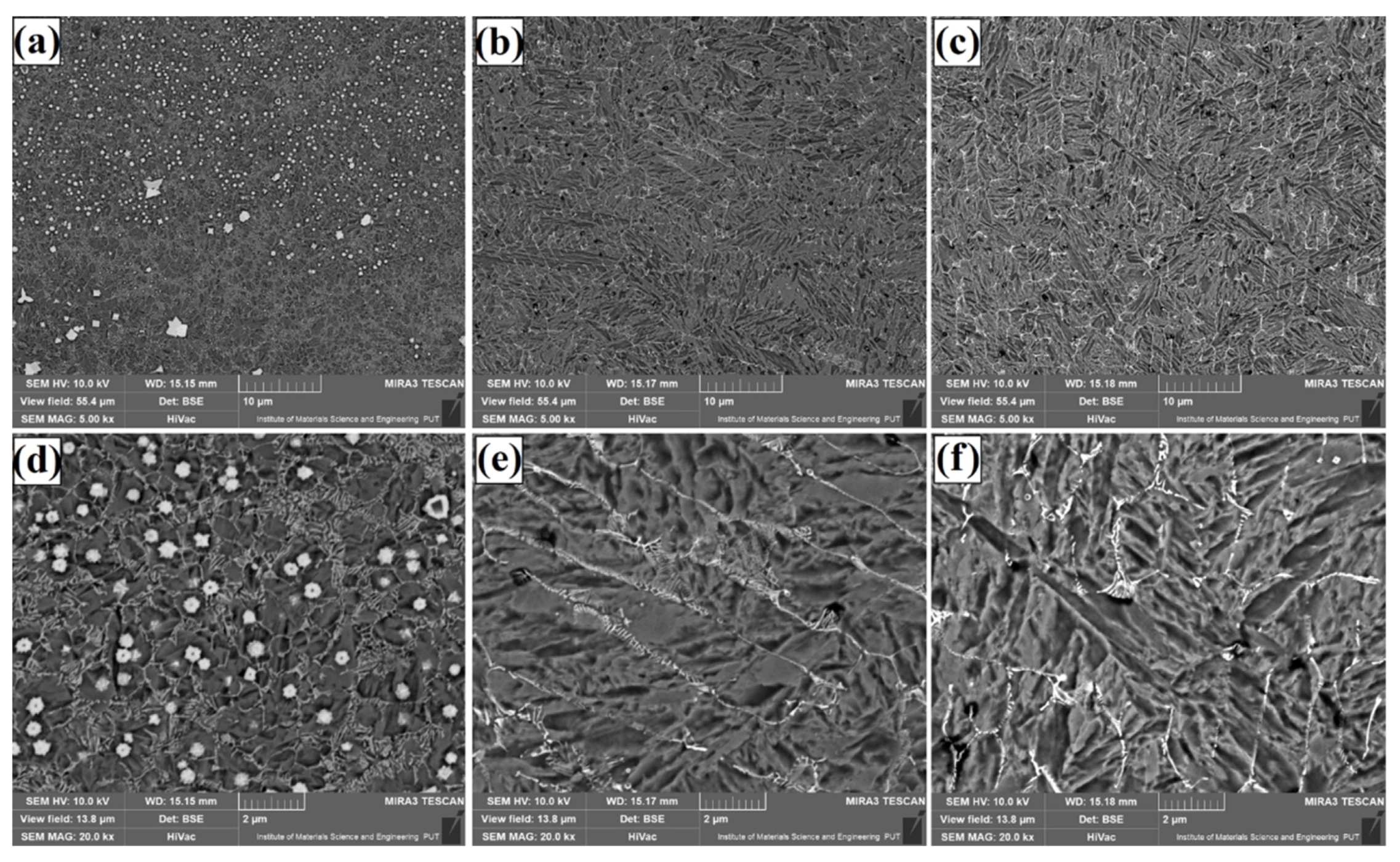
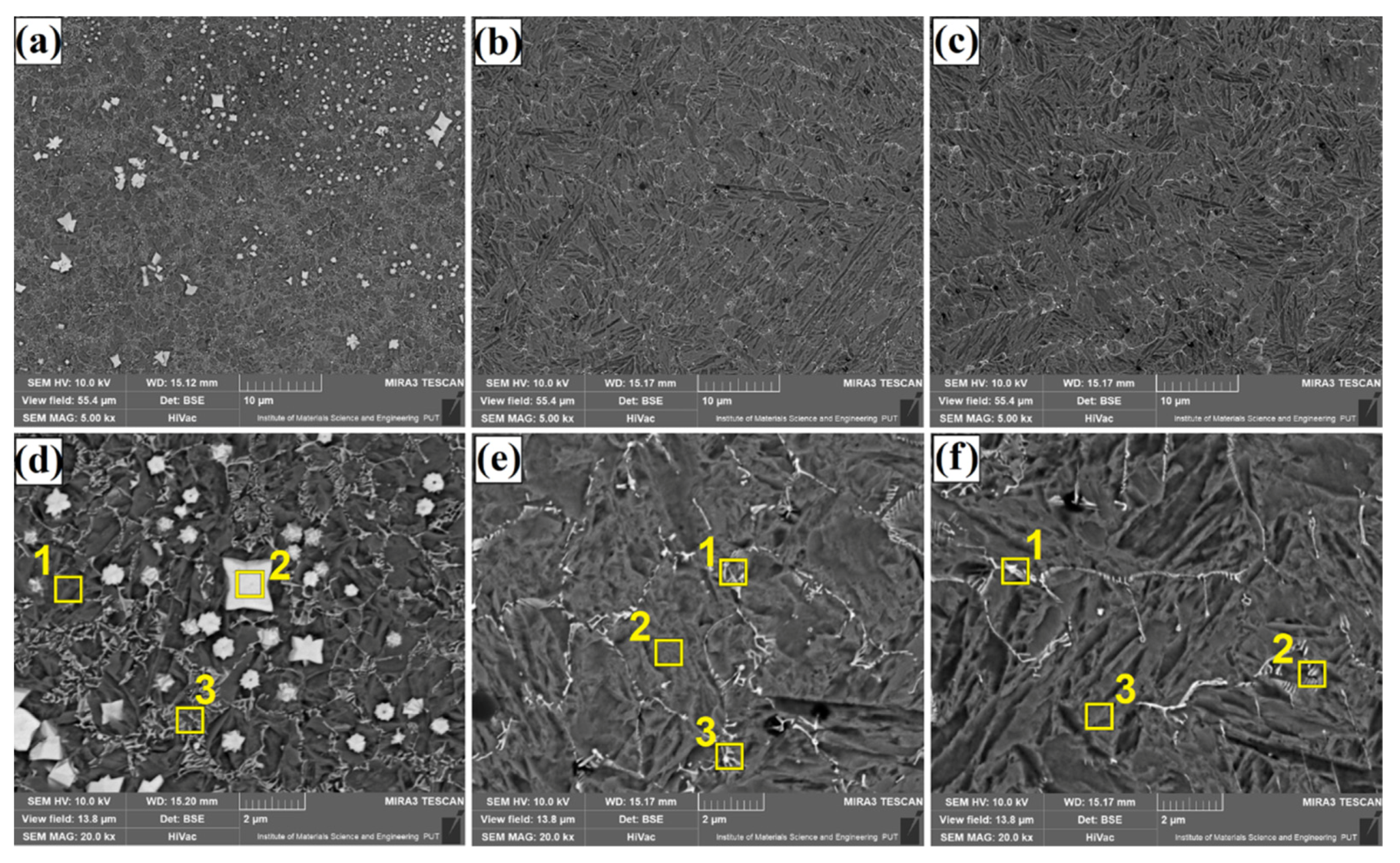
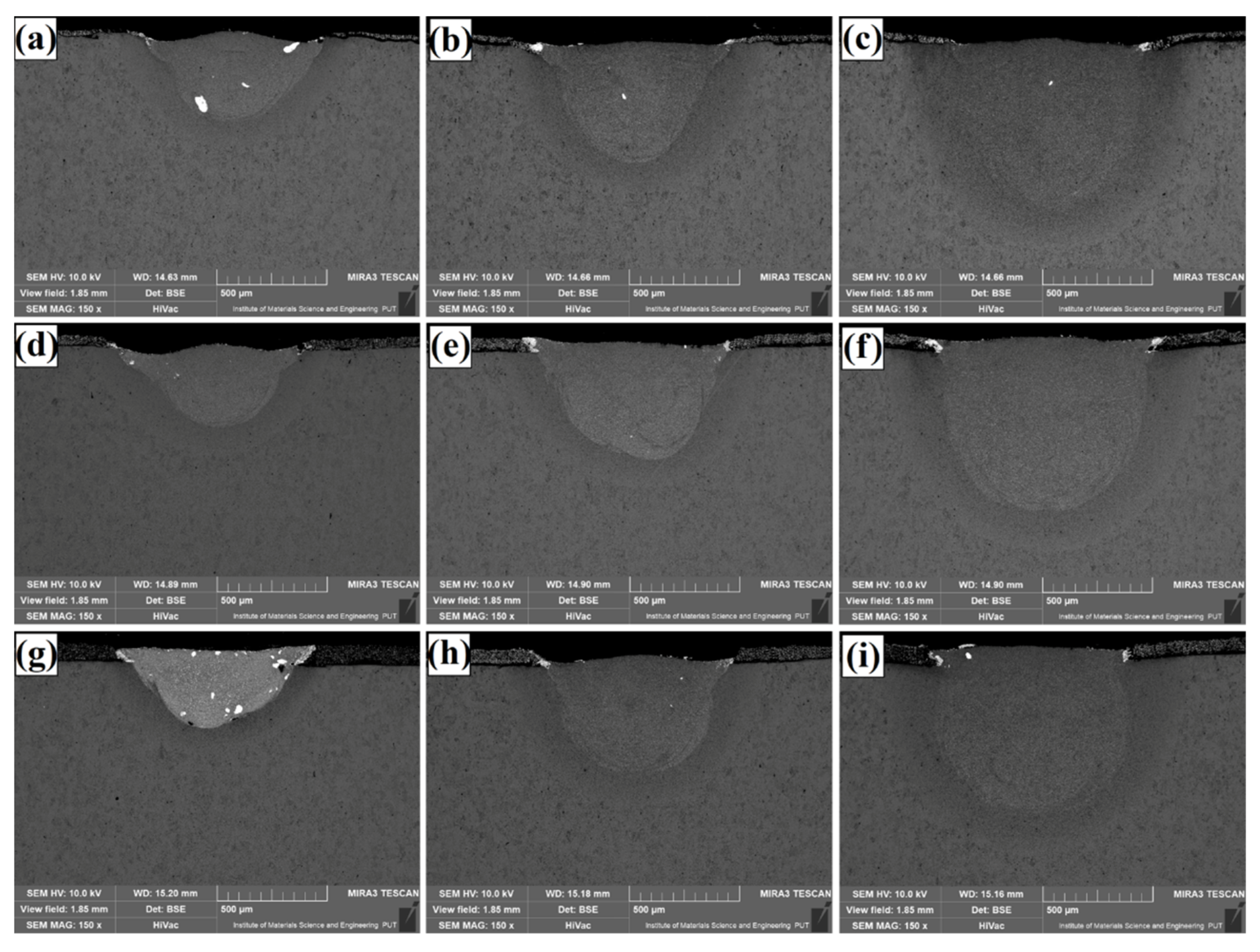
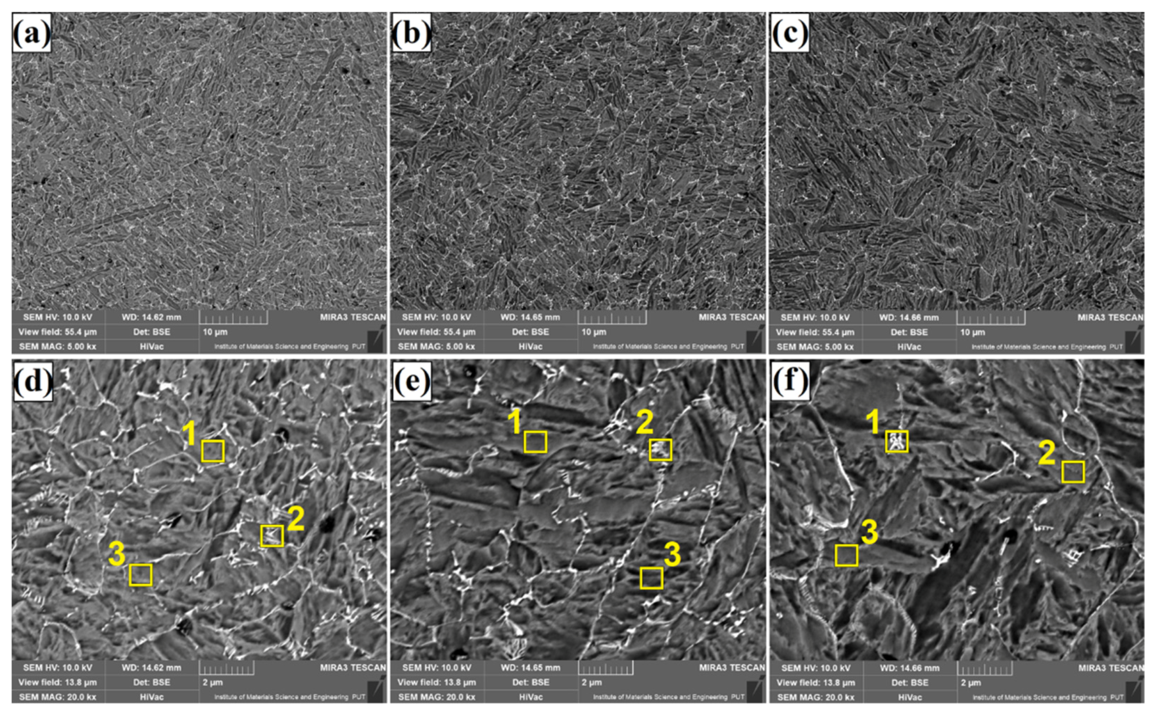
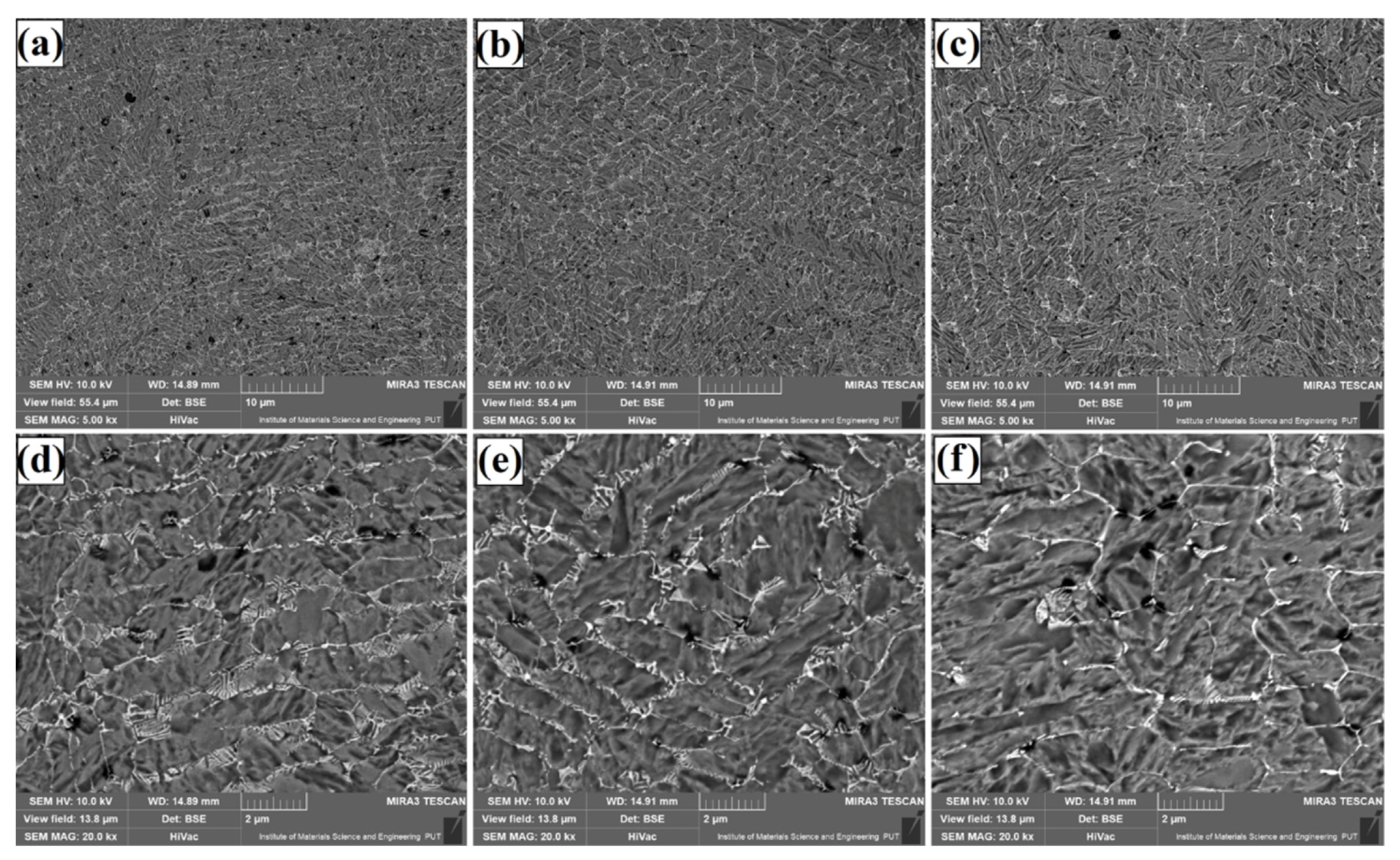
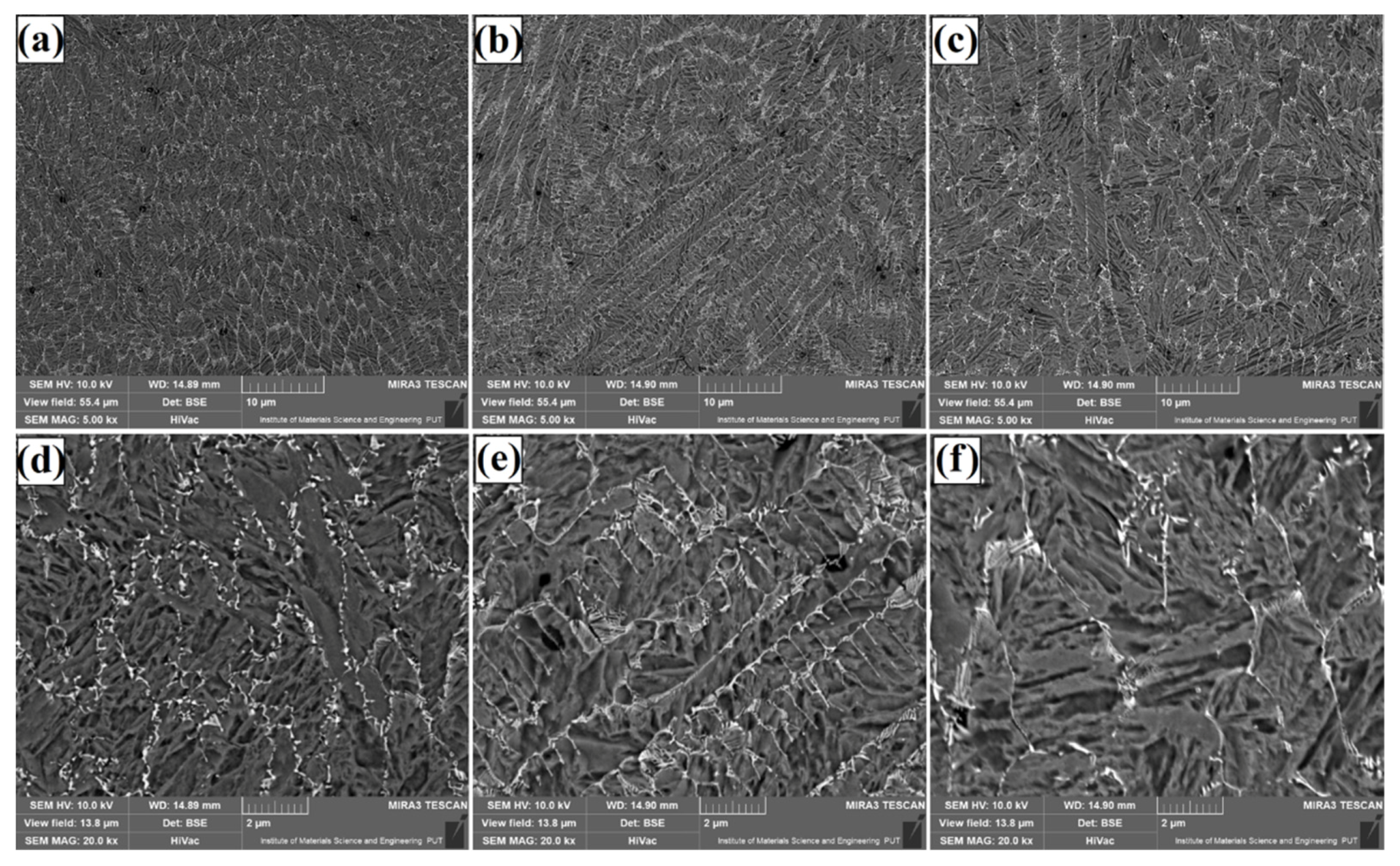
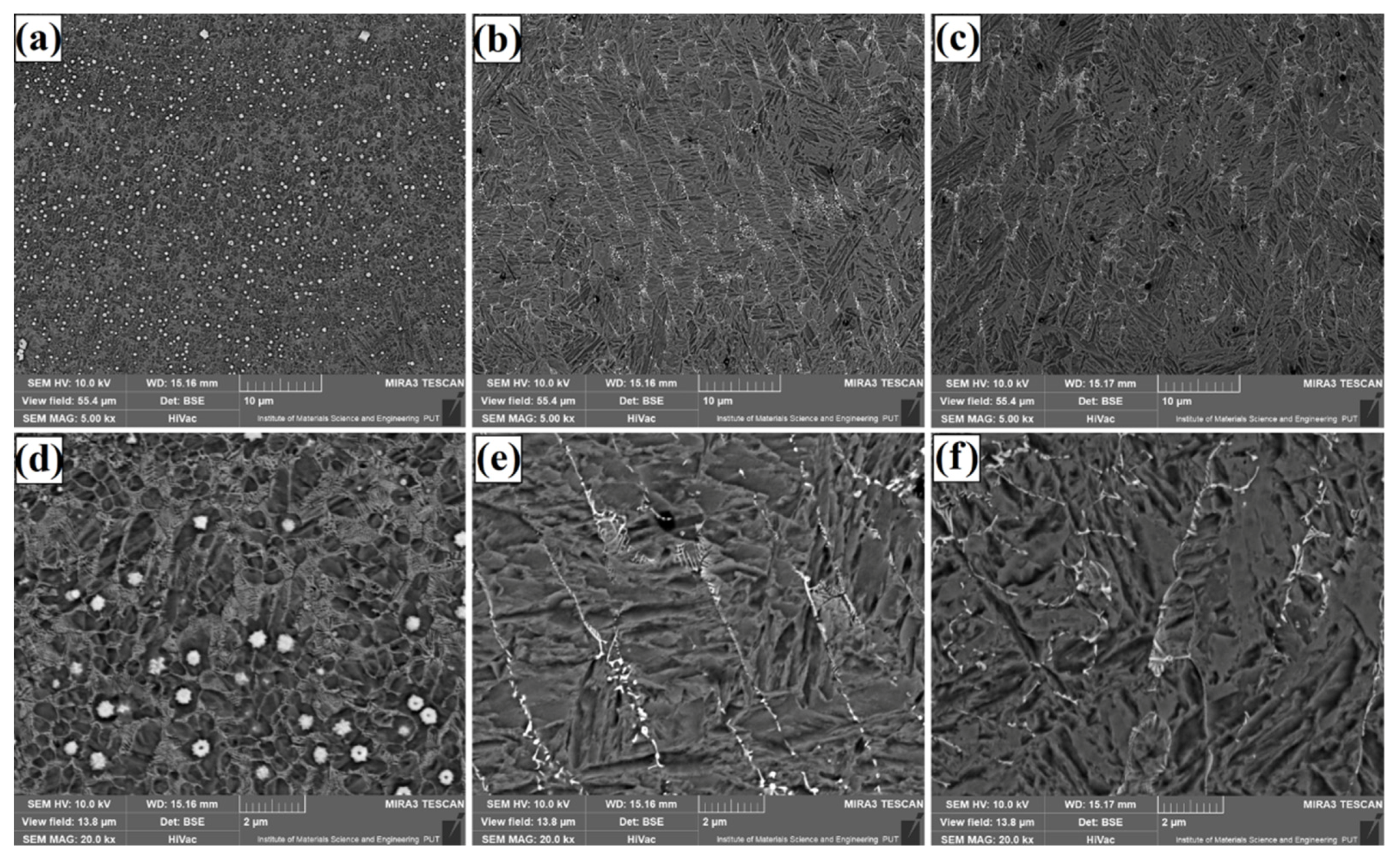
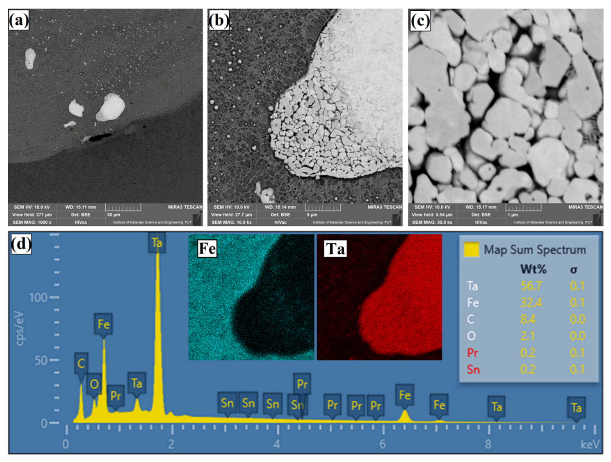
3.1. Microstructure
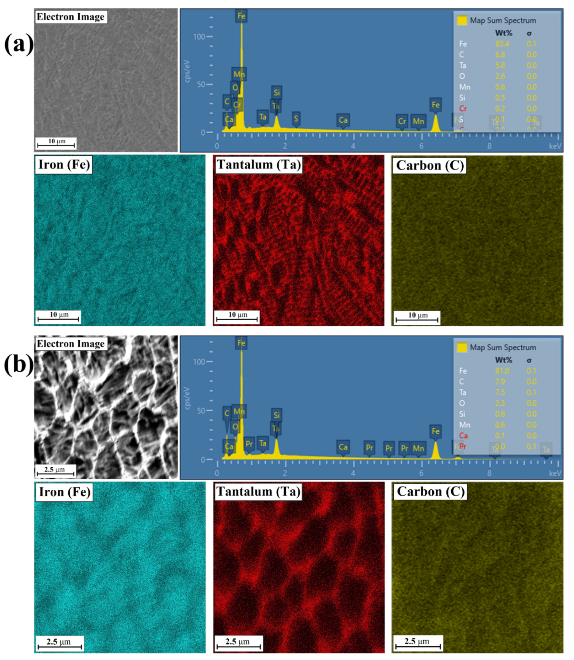
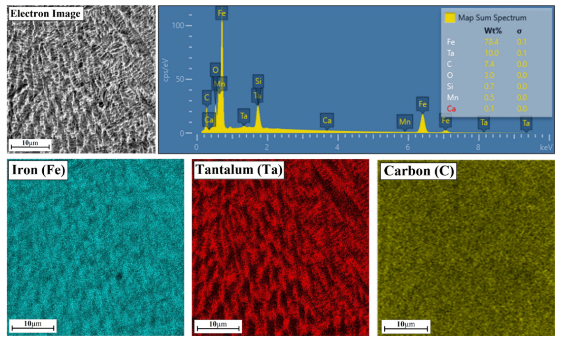
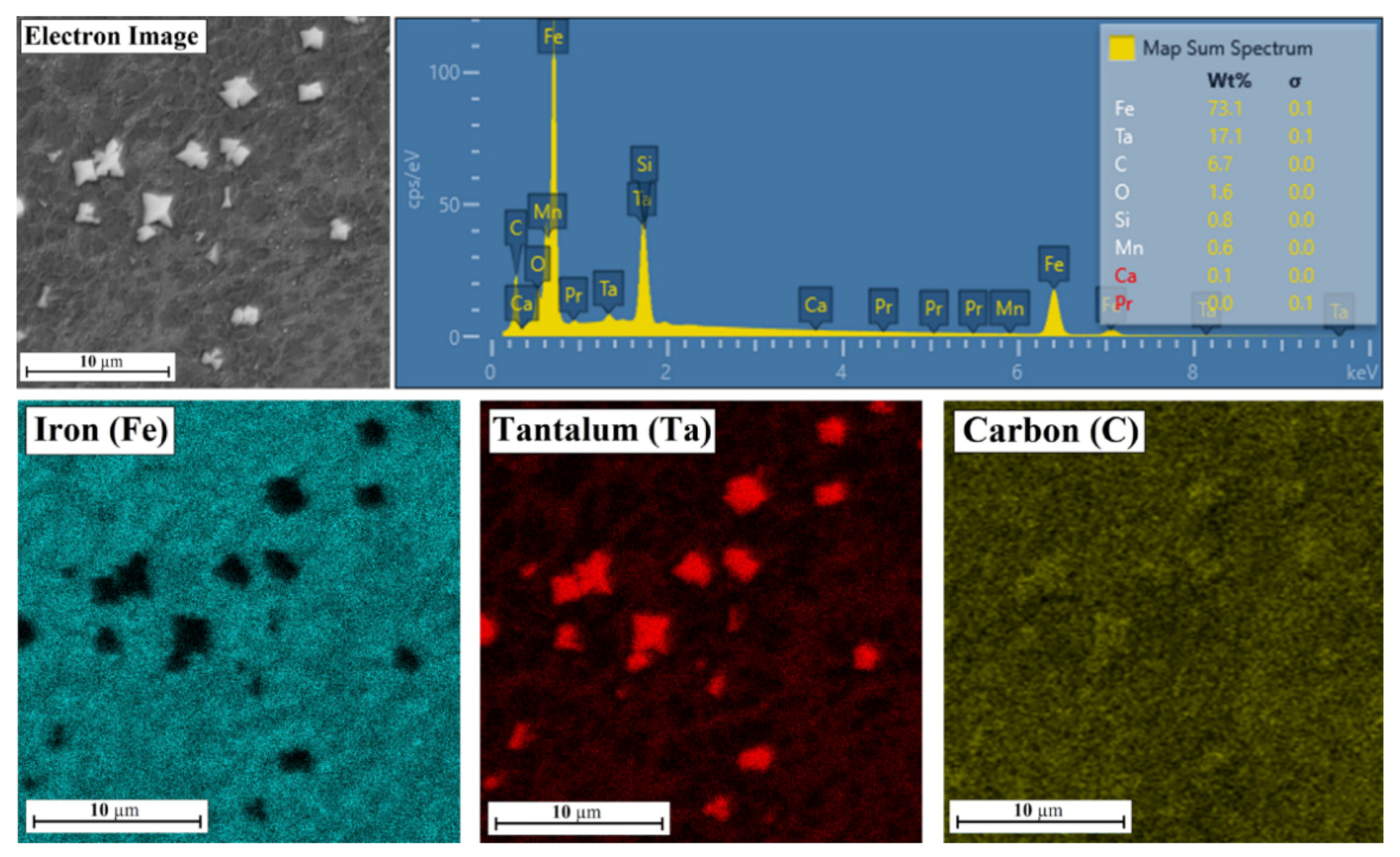
3.2. Chemcial Composition
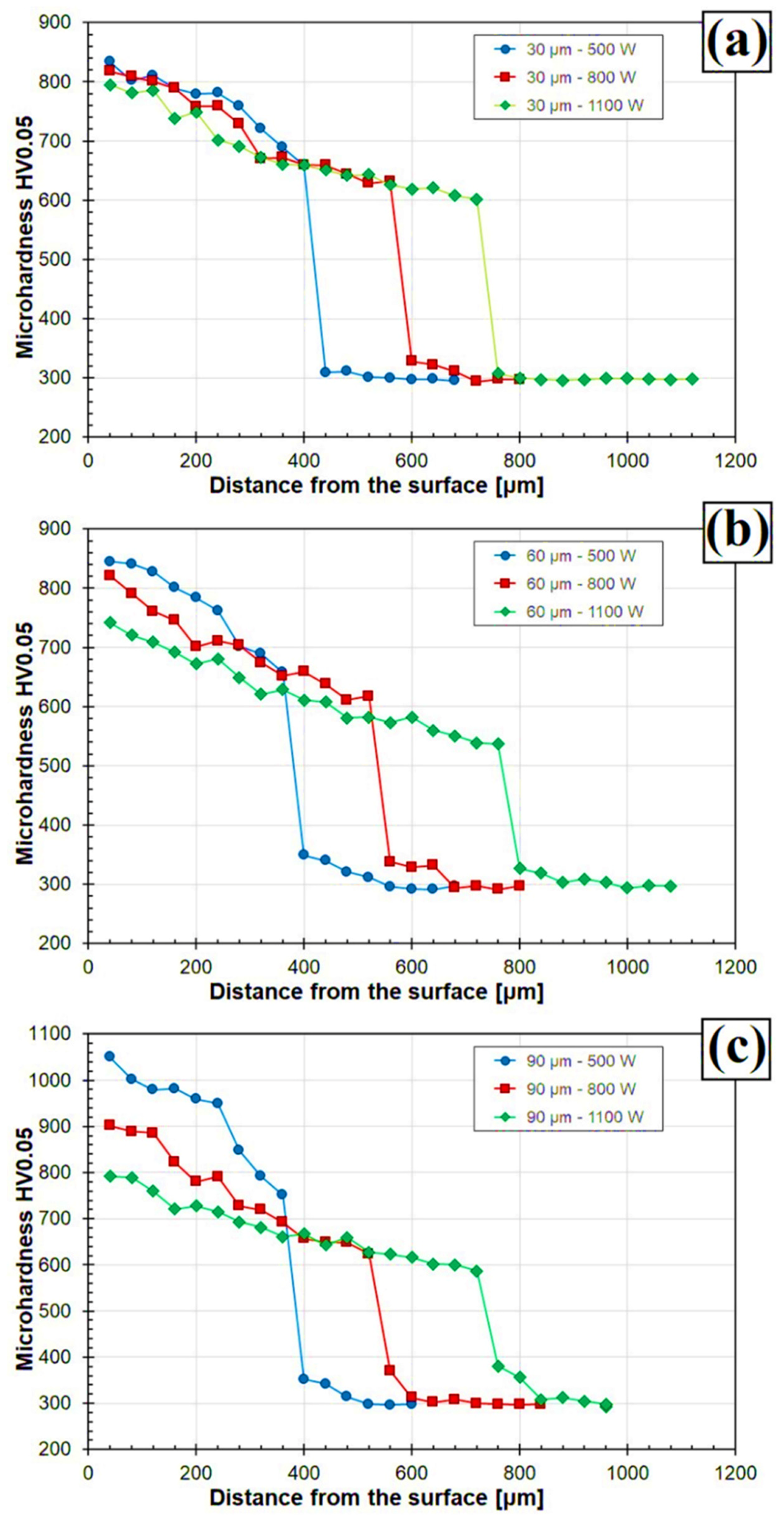
3.3. Microhardness
4. Conclusions
- With laser processing it is possible to produce Fe/TaC metal matrix composite coatings in which the matrix is the iron from a steel substrate enriched with tantalum, and the reinforcing phase are primary TaC tantalum carbide particles.
- Pre-coating thickness and laser beam power have a significant influence on the properties of metal matrix composite Fe/TaC coating. Application of an excessively thin pre-coating or the use of too high laser beam power leads to complete remelting of primary carbides as well as to increase in the iron content in newly formed coatings.
- A complete remelting of primary TaC particles leads to formation of a carbide eutectic in the form of a mesh at grain boundaries.
- The formation of a typical composite coating is also dependent on the size of the primary TaC particles introduced in laser processing. The smallest powder particles melt completely and larger particles partially melt to form structures in the form of flakes, rosettes or polygons.
- The amount of TaC primary carbides introduced into the steel surface has a significant impact on the microhardness of obtained Fe/TaC coatings. Furthermore, the primary carbide particles cannot be completely melted because this reduces the general hardness of the coating.
Funding
Institutional Review Board Statement
Informed Consent Statement
Data Availability Statement
Acknowledgments
Conflicts of Interest
References
- Hu, D.; Liu, Y.; Chen, H.; Wang, M.; Liu, J. Microstructure and properties of in-situ synthesized Ni3Ta-TaC reinforced Ni-based coatings by laser cladding. Surf. Coat. Technol. 2021, 405, 126599. [Google Scholar] [CrossRef]
- Bartkowski, D.; Młynarczak, A.; Piasecki, A.; Dudziak, B.; Gościański, M.; Bartkowska, A. Microstructure, microhardness and corrosion resistance of Stellite-6 coatings reinforced with WC particles using laser cladding. Opt. Laser Technol. 2015, 68, 191–201. [Google Scholar] [CrossRef]
- Yu, T.; Deng, Q.L.; Zheng, J.F.; Dong, G.; Yang, J.G. Microstructure and wear behaviour of laser clad NiCrBSi+Ta composite coating. Surf. Eng. 2012, 28, 357–363. [Google Scholar] [CrossRef]
- Yu, T.; Deng, Q.; Dong, G.; Yang, J. Influence of Ta on microstructure and abrasive wear resistance of laser clad NiCrSiB coating. J. Wuhan Univ. Technol. Sci. Ed. 2013, 28, 437–443. [Google Scholar] [CrossRef]
- Bartkowski, D.; Bartkowska, A.; Jurči, P. Laser cladding process of Fe/WC metal matrix composite coatings on low carbon steel using Yb: YAG disk laser. Opt. Laser Technol. 2021, 136, 106784. [Google Scholar] [CrossRef]
- Lu, J.; Cao, J.; Lu, H.; Zhang, L.; Luo, K. Wear properties and microstructural analyses of Fe-based coatings with various WC contents on H13 die steel by laser cladding. Surf. Coat. Technol. 2019, 369, 228–237. [Google Scholar] [CrossRef]
- Zhou, S.; Dai, X.; Zheng, H. Microstructure and wear resistance of Fe-based WC coating by multi-track overlapping laser induction hybrid rapid cladding. Opt. Laser Technol. 2012, 44, 190–197. [Google Scholar] [CrossRef]
- Zhou, S.; Dai, X. Microstructure evolution of Fe-based WC composite coating prepared by laser induction hybrid rapid cladding. Appl. Surf. Sci. 2010, 256, 7395–7399. [Google Scholar] [CrossRef]
- Wang, J.; Li, L.; Tao, W. Crack initiation and propagation behavior of WC particles reinforced Fe-based metal matrix composite produced by laser melting deposition. Opt. Laser Technol. 2016, 82, 170–182. [Google Scholar] [CrossRef]
- Zhang, Z.; Chen, Y.; Zuo, L.; Zhang, Y.; Qi, Y.; Gao, K. The effect of volume fraction of WC particles on wear behavior of in-situ WC/Fe composites by spark plasma sintering. Int. J. Refract. Met. Hard Mater. 2017, 69, 196–208. [Google Scholar] [CrossRef]
- Zhou, S.; Xu, Y.; Liao, B.; Sun, Y.; Dai, X.; Yang, J.; Li, Z. Effect of laser remelting on microstructure and properties of WC reinforced Fe-based amorphous composite coatings by laser cladding. Opt. Laser Technol. 2018, 103, 8–16. [Google Scholar] [CrossRef] [Green Version]
- Dai, Q.-L.; Luo, C.-B.; You, F.-Y. Crack Restraining Methods and their Effects on the Microstructures and Properties of Laser Cladded WC/Fe Coatings. Materials 2018, 11, 2541. [Google Scholar] [CrossRef] [Green Version]
- Fan, L.; Dong, Y.; Chen, H.; Dong, L.; Yin, Y. Wear Properties of Plasma Transferred Arc Fe-based Coatings Reinforced by Spherical WC Particles. J. Wuhan Univ. Technol. Mat. Sci. Ed. 2019, 34, 433–439. [Google Scholar] [CrossRef]
- Zhou, S.; Zeng, X. Growth characteristics and mechanism of carbides precipitated in WC–Fe composite coatings by laser induction hybrid rapid cladding. J. Alloys Compd. 2010, 505, 685–691. [Google Scholar] [CrossRef]
- Chang, C.-M.; Lin, C.-M.; Hsieh, C.-C.; Chen, J.-H.; Wu, W. Micro-structural characteristics of Fe–40wt%Cr–xC hardfacing alloys with [1.0–4.0wt%] carbon content. J. Alloys Compd. 2009, 487, 83–89. [Google Scholar] [CrossRef]
- Ma, Q.; Li, Y.; Wang, J.; Kun, L. Microstructure evolution and growth control of ceramic particles in wide-band laser clad Ni60/WC composite coatings. Mater Design 2016, 92, 897–905. [Google Scholar] [CrossRef]
- Li, Z.; Yan, H.; Zhang, P.; Guo, J.; Yu, Z.; Ringsberg, J.W. Improving surface resistance to wear and corrosion of nickel-aluminum bronze by laser-clad TaC/Co-based alloy composite coatings. Surf. Coat. Technol. 2021, 405, 126592. [Google Scholar] [CrossRef]
- Yu, T.; Deng, Q.; Dong, G.; Yang, J. Effects of Ta on microstructure and microhardness of Ni based laser clad coating. Appl. Surf. Sci. 2011, 257, 5098–5103. [Google Scholar] [CrossRef]
- Chao, M.-J.; Wang, W.-L.; Liang, E.-J.; Ouyang, D. Microstructure and wear resistance of TaC reinforced Ni-based coating by laser cladding. Surf. Coat. Technol. 2008, 202, 1918–1922. [Google Scholar] [CrossRef]
- Yi, Y.; Lomg, S.; Zhang, R.; Wu, C.; Zhou, S. Influence of Al2O3 particles on the tribological properties of CoCrAlYTa coating produced by laser-induction hybrid cladding. Ceram. Int. 2021, 47, 19434–19442. [Google Scholar] [CrossRef]
- Lv, Y.; Li, J.; Tao, Y.; Hu, L. Oxidation behaviors of the TiNi/Ti2Ni matrix composite coatings with different contents of TaC addition fabricated on Ti6Al4V by laser cladding. J. Alloys Compd. 2016, 679, 202–212. [Google Scholar] [CrossRef]
- Murzakov, M.; Petrovskiy, V.; Birukov, V.; Dzhumaev, P.; Polski, V.; Markushov, Y.; Bykovskiy, D. Structure Formation and Properties of Weld Overlay Produced by Laser Cladding under the Influence of Nanoparticles of High-melting Compounds. Phys. Procedia 2015, 71, 202–206. [Google Scholar] [CrossRef] [Green Version]
- Murzakov, M.; Petrovskiy, V.N.; Bykovskiy, D.P.; Andreev, A.; Birukov, V.P.; Markushov, Y.V. Receiving Wear-Resistance Coverings Additives of Nanoparticles of Refractory Metals at a Laser Cladding. J. Phys. Conf. Ser. 2016, 691, 12009. [Google Scholar] [CrossRef] [Green Version]
- Murzakov, M.; Chirikov, S.; Markushov, Y.V. Research on microstructure and wear resistance of coatings obtained by adding nanoparticles of refractory compounds in laser cladding. J. Phys. Conf. Ser. 2016, 747, 12062. [Google Scholar] [CrossRef] [Green Version]
- Murzakov, M.; Petrovskiy, V.N.; Polski, V.; Mironov, V.D.; Prokopova, N.M.; Tret’Yakov, E.V. Influence of additions of nanoparticles TaC on a microstructure laser cladding. J. Phys. Conf. Ser. 2015, 594, 12032. [Google Scholar] [CrossRef] [Green Version]
- Zhao, P.; Li, J.; Lei, R.; Yuan, B.; Xia, M.; Li, X.; Zhang, Y. Investigation into Microstructure, Wear Resistance in Air and NaCl Solution of AlCrCoNiFeCTax High-Entropy Alloy Coatings Fabricated by Laser Cladding. Coatings 2021, 11, 358. [Google Scholar] [CrossRef]
- Bartkowski, D.; Bartkowska, A.; Piasecki, A.; Jurči, P. Influence of Laser Cladding Parameters on Microstructure, Microhardness, Chemical Composition, Wear and Corrosion Resistance of Fe–B Composite Coatings Reinforced with B4C and Si Particles. Coatings 2020, 10, 809. [Google Scholar] [CrossRef]
- Czerwinski, F. Heat Treatment—Conventional and Novel Applications; Intech Open: London, UK, 2012. [Google Scholar] [CrossRef]
- Burakowski, T.; Wierzchon, T. Surface Engineering of Metals. Principles, Equipment, Technologies; CRC Press: Boca Raton, FL, USA, 2020; ISBN 9780367400125. [Google Scholar]
- Lawrence, J.R.; Waugh, D. Laser Surface Engineering: Processes and Applications, 1st ed.; Woodhead Publishing Series in Metals and Surface Engineering Book; Kindle Edition; Woodhead Publishing: Sawston, UK, 2014. [Google Scholar]
- Di, C.; Yan, X.; Lv, X.; Yan, C.; Ye, W.; Li, D. Effect of Vacuum Carburizing Time on Microstructure and Mechanical Properties of Tantalum Carbide Layer. Met. Mater. Int. 2021, 1–9. [Google Scholar] [CrossRef]
- Bartkowski, D.; Bartkowska, A.; Popławski, M.; Przestacki, D. Microstructure, Microhardness, Corrosion and Wear Resistance of B, Si and B-Si Coatings Produced on C45 Steel Using Laser Processing. Metals 2020, 10, 792. [Google Scholar] [CrossRef]
- Bartkowska, A.; Bartkowski, D.; Popławski, M.; Piasecki, A.; Przestacki, D.; Miklaszewski, A. Microstructure, Microhardness, Corrosion Resistance and Chemical Composition of Mo, B and Mo-B Coatings Produced Using Laser Processing. Materials 2020, 13, 3249. [Google Scholar] [CrossRef]


| C | Mn | Si | P | S | Cr | V |
|---|---|---|---|---|---|---|
| 1.35 | 0.60 | 0.30 | 0.02 | 0.02 | 1.45 | 0.20 |
| Fe/TaC Coatings | MZ (µm) | HAZ (µm) | TT (µm) |
|---|---|---|---|
| Pre-coat 30 µm, 500 W | 401 | 162 | 563 |
| Pre-coat 30 µm, 800 W | 552 | 133 | 685 |
| Pre-coat 30 µm, 1100 W | 763 | 229 | 992 |
| Pre-coat 60 µm, 500 W | 371 | 157 | 528 |
| Pre-coat 60 µm, 800 W | 543 | 151 | 694 |
| Pre-coat 60 µm, 1100 W | 760 | 205 | 965 |
| Pre-coat 90 µm, 500 W | 349 | 122 | 471 |
| Pre-coat 90 µm, 800 W | 542 | 169 | 711 |
| Pre-coat 90 µm, 1100 W | 751 | 205 | 956 |
| Fe/TaC Coating | Number of Measurement | Ta [wt.%] | C [wt.%] | Fe [wt.%] |
|---|---|---|---|---|
| Pre-coat 30 µm, 500 W | 1 | 5.1 | 8.0 | 86.9 |
| 2 | 17.9 | 9.2 | 72.9 | |
| 3 | 6.3 | 9.0 | 84.7 | |
| Pre-coat 30 µm, 800 W | 1 | 5.5 | 15.5 | 79.0 |
| 2 | 22.8 | 15.3 | 61.9 | |
| 3 | 6.9 | 13.9 | 79.2 | |
| Pre-coat 30 µm, 1100 W | 1 | 18.1 | 9.7 | 72.2 |
| 2 | 1.7 | 9.4 | 88.9 | |
| 3 | 2.1 | 8.7 | 89.2 | |
| Pre-coat 60 µm, 500 W | 1 | 26.2 | 10.1 | 63.7 |
| 2 | 24.6 | 11.8 | 63.6 | |
| 3 | 2.9 | 9.1 | 88.0 | |
| Pre-coat 60 µm, 800 W | 1 | 26.7 | 10.5 | 62.8 |
| 2 | 4.7 | 7.5 | 87.8 | |
| 3 | 26.5 | 9.8 | 63.7 | |
| Pre-coat 60 µm, 1100 W | 1 | 4.3 | 11.0 | 84.7 |
| 2 | 3.8 | 9.3 | 86.9 | |
| 3 | 22.9 | 11.4 | 65.7 | |
| Pre-coat 90 µm, 500 W | 1 | 17.0 | 9.8 | 73.2 |
| 2 | 63.5 | 8.7 | 27.8 | |
| 3 | 26.3 | 11.4 | 62.3 | |
| Pre-coat 90 µm, 800 W | 1 | 21.7 | 16.3 | 62.0 |
| 2 | 2.9 | 16.5 | 80.6 | |
| 3 | 20.7 | 17.7 | 61.6 | |
| Pre-coat 90 µm, 1100 W | 1 | 19.4 | 14.8 | 65.8 |
| 2 | 22.9 | 17.2 | 59.9 | |
| 3 | 2.9 | 16.0 | 81.1 |
Publisher’s Note: MDPI stays neutral with regard to jurisdictional claims in published maps and institutional affiliations. |
© 2021 by the author. Licensee MDPI, Basel, Switzerland. This article is an open access article distributed under the terms and conditions of the Creative Commons Attribution (CC BY) license (https://creativecommons.org/licenses/by/4.0/).
Share and Cite
Bartkowski, D. Manufacturing Technology and Properties of Fe/TaC Metal Matrix Composite Coatings Produced on Medium Carbon Steel Using Laser Processing—Preliminary Study on the Single Laser Tracks. Materials 2021, 14, 5367. https://doi.org/10.3390/ma14185367
Bartkowski D. Manufacturing Technology and Properties of Fe/TaC Metal Matrix Composite Coatings Produced on Medium Carbon Steel Using Laser Processing—Preliminary Study on the Single Laser Tracks. Materials. 2021; 14(18):5367. https://doi.org/10.3390/ma14185367
Chicago/Turabian StyleBartkowski, Dariusz. 2021. "Manufacturing Technology and Properties of Fe/TaC Metal Matrix Composite Coatings Produced on Medium Carbon Steel Using Laser Processing—Preliminary Study on the Single Laser Tracks" Materials 14, no. 18: 5367. https://doi.org/10.3390/ma14185367
APA StyleBartkowski, D. (2021). Manufacturing Technology and Properties of Fe/TaC Metal Matrix Composite Coatings Produced on Medium Carbon Steel Using Laser Processing—Preliminary Study on the Single Laser Tracks. Materials, 14(18), 5367. https://doi.org/10.3390/ma14185367