
Experimental and Numerical Study of Shear Interface Response of Hybrid Thin CFRP–Concrete Slabs


Abstract
1. Introduction
2. Experimental Program
2.1. Materials
2.1.1. Concrete
2.1.2. CFRP Sheets
2.1.3. Mesh
2.1.4. Sand and Gravel
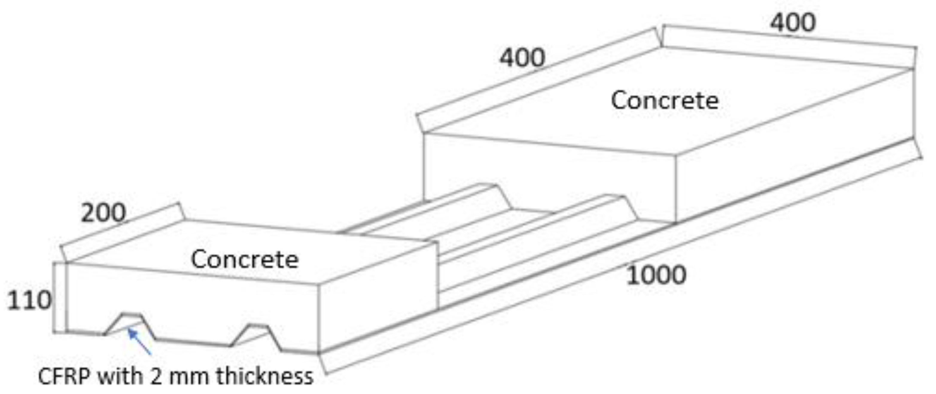
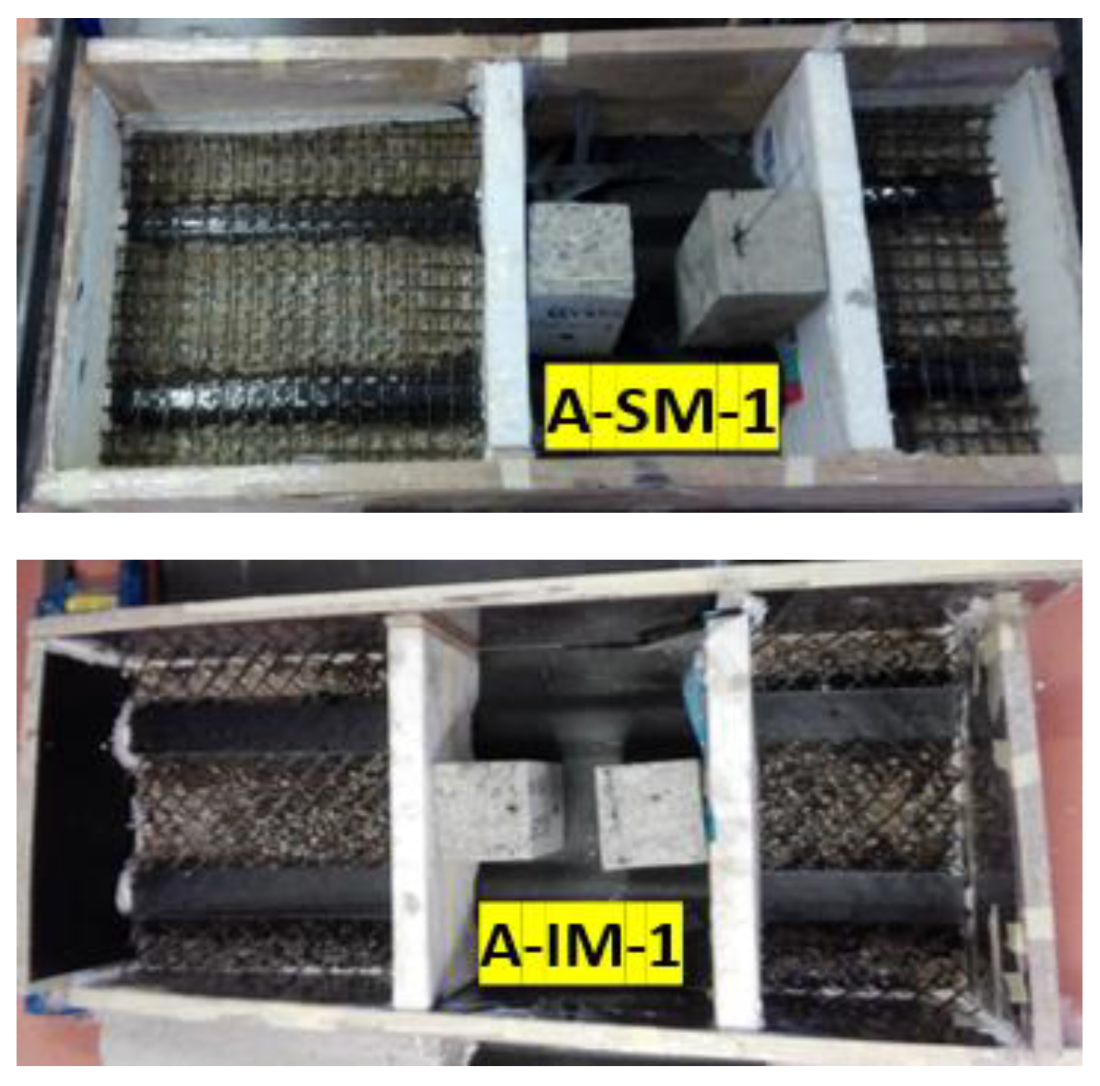
2.2. Specimens
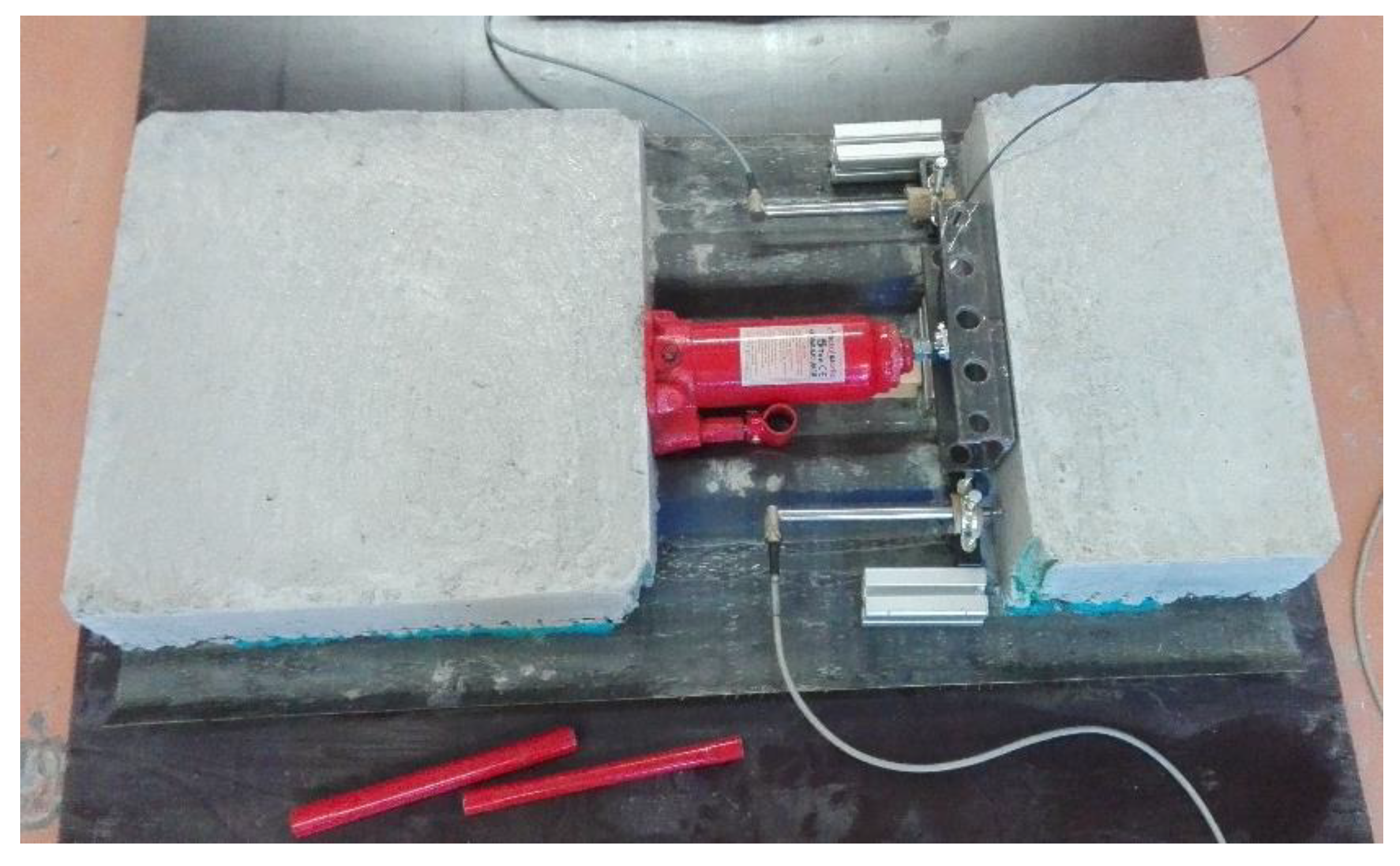
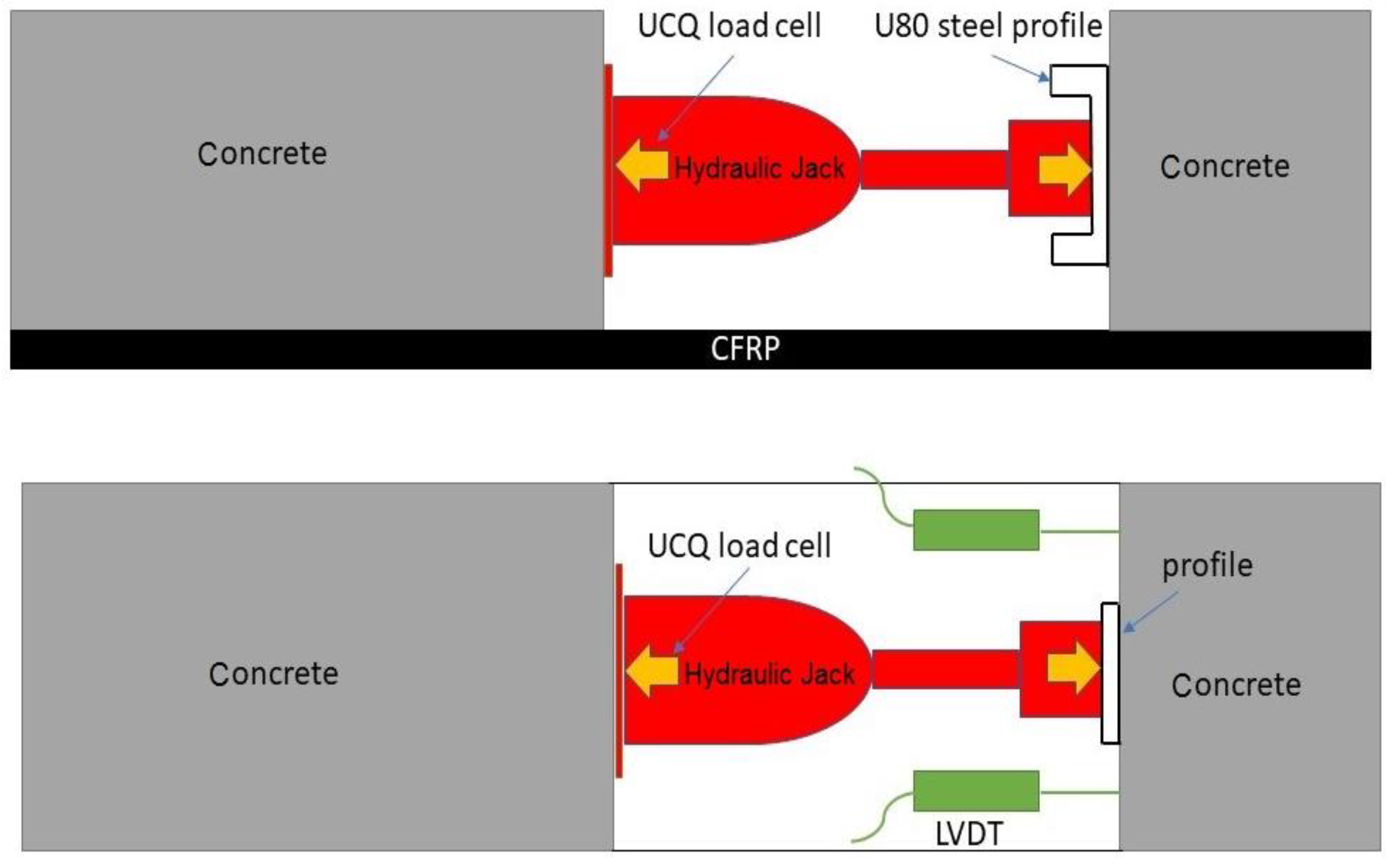
2.3. Test Setup
3. Experimental Results and Discussion
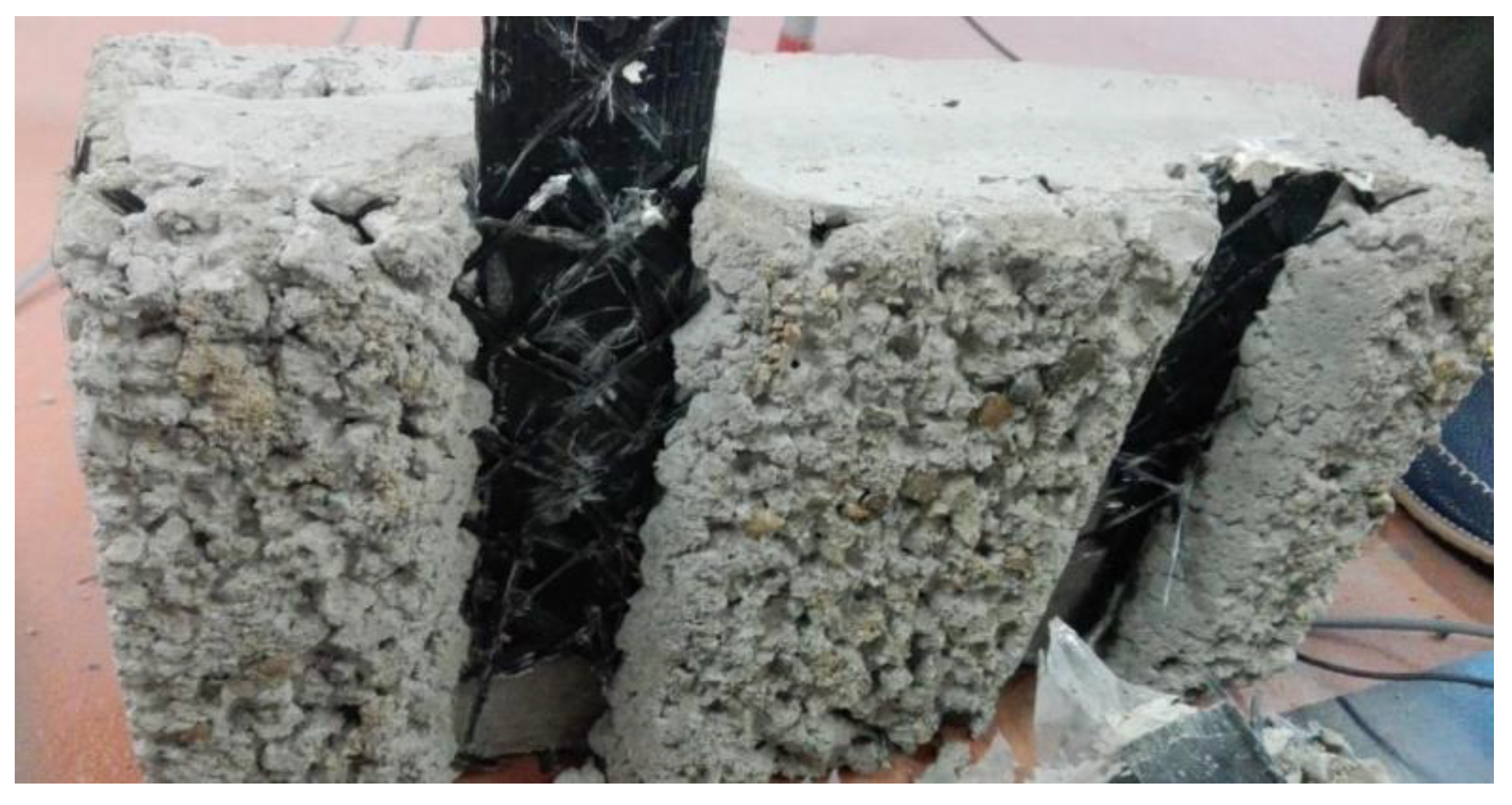
3.1. The Failure Process
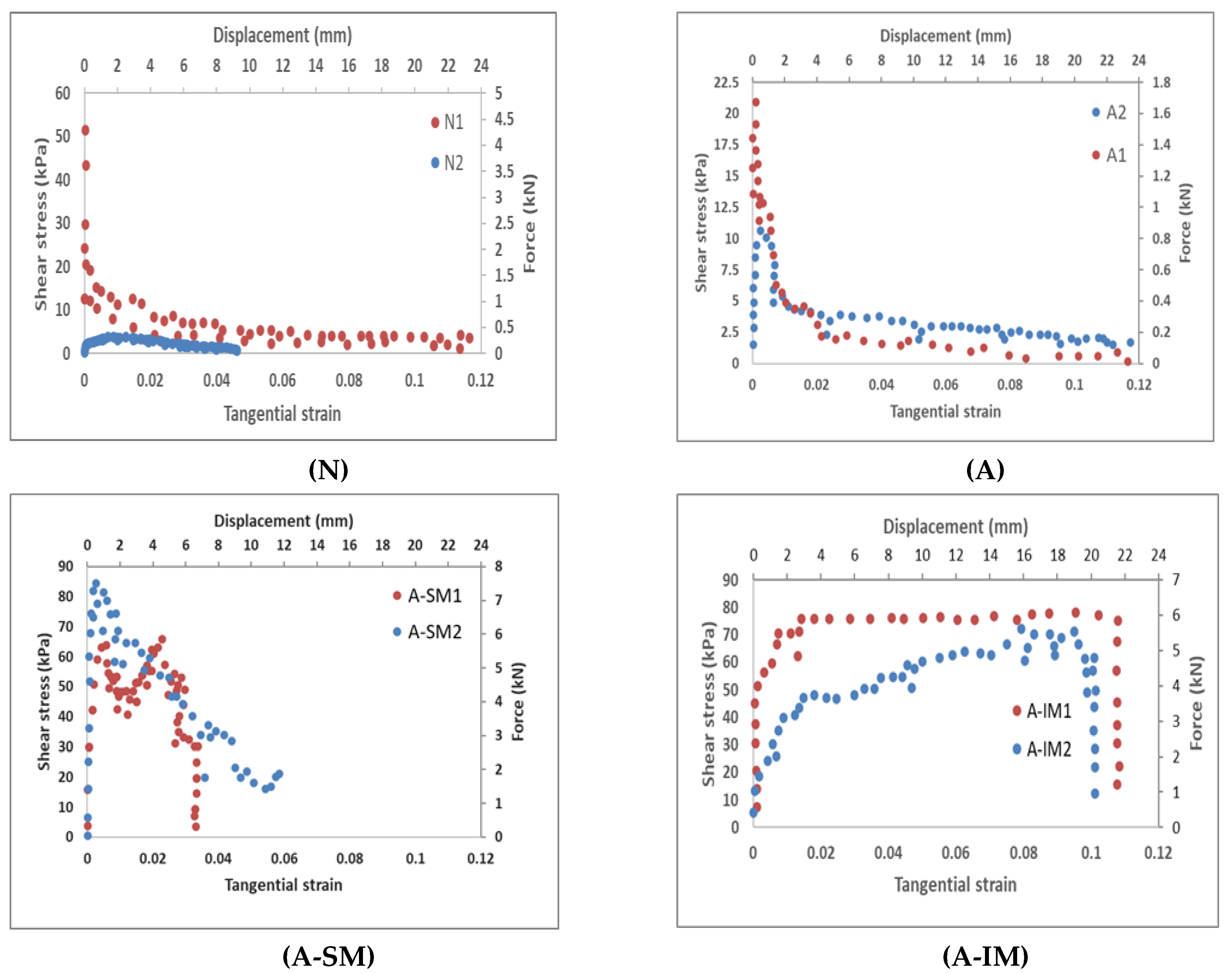
3.2. Comparison of Results
4. Finite Element Method Simulations
4.1. Geometry
4.2. Materials
4.3. Contacts
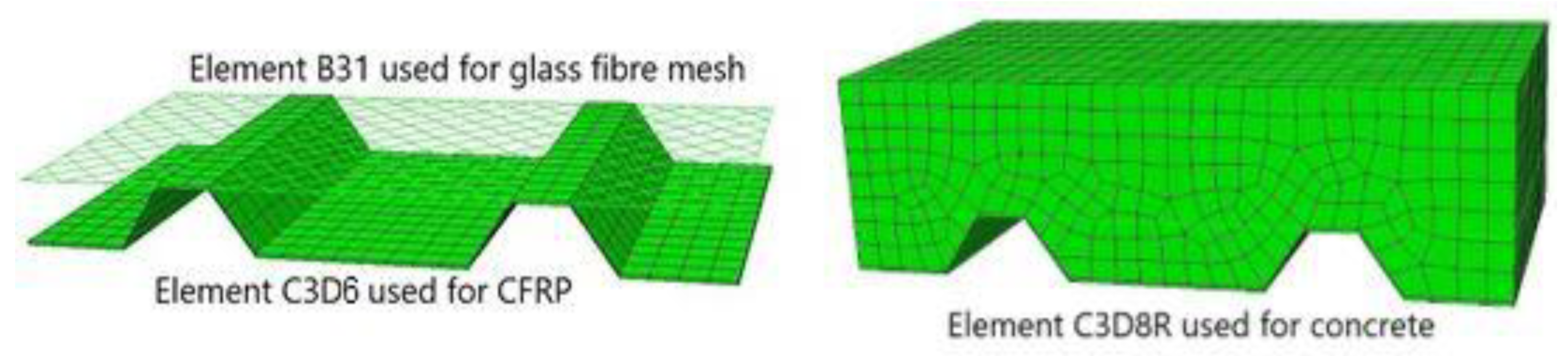
4.4. Mesh
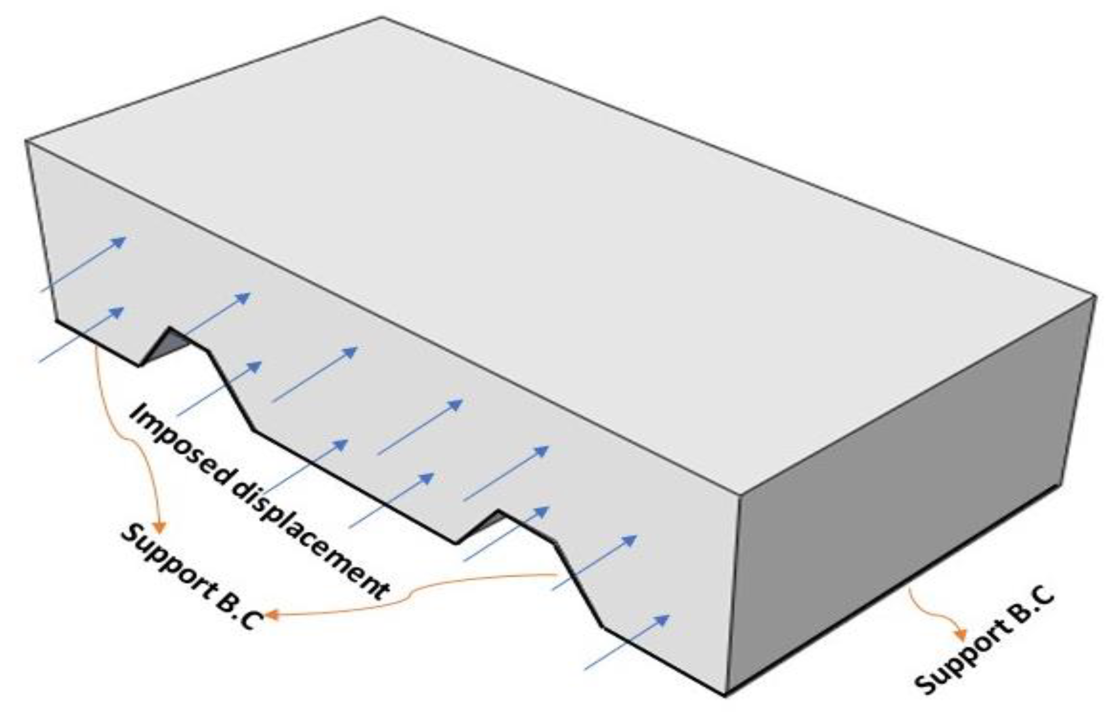
4.5. Boundary Conditions
5. Numerical Results and Discussion
Numerical Results
6. Conclusions
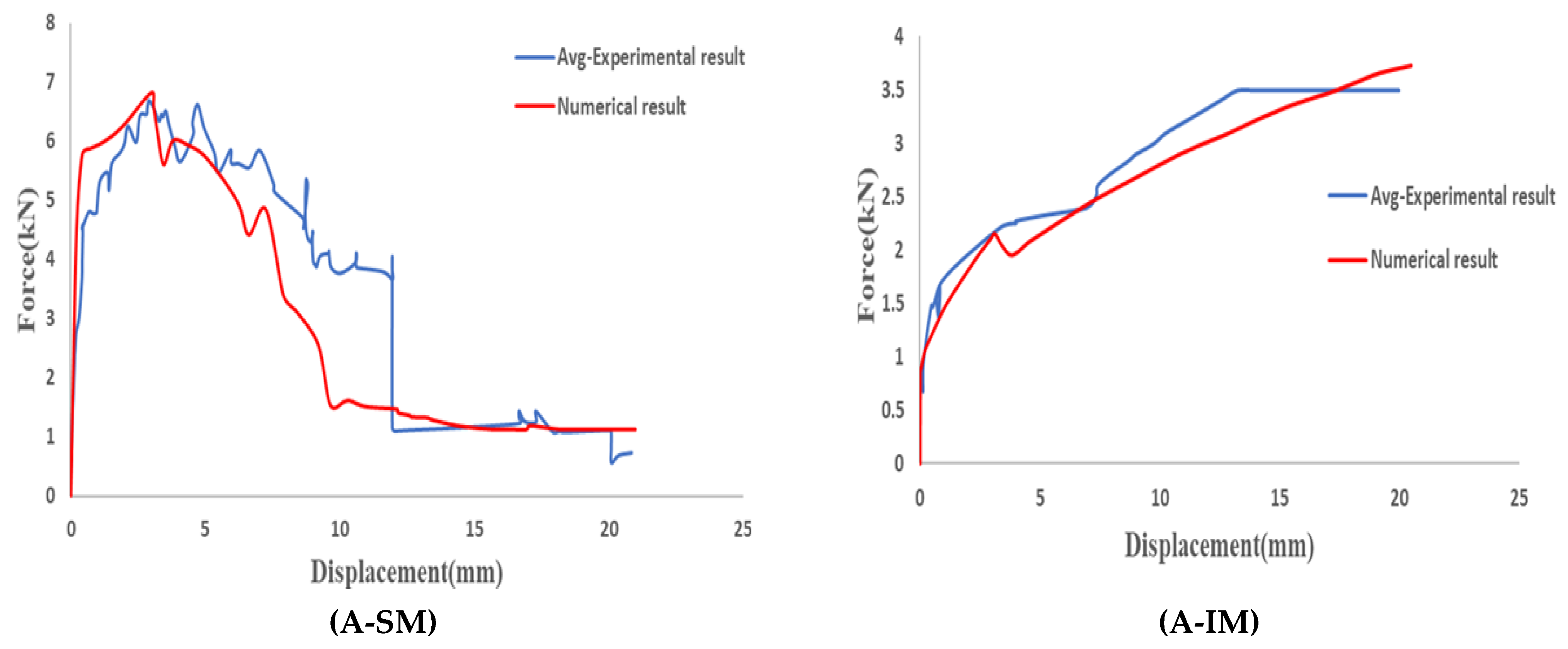
- Specimens without connectors (N) and those with only aggregate connections (A) presented the weakest shear resistance. The performance was fragile in all cases, with sudden failure. The post-critical response was related to merely friction between materials, not allowing significant energy dissipation. Both connections are considered unreliable for real works, disregarding even the classical connection approach of increasing the roughness via aggregate adhesion.
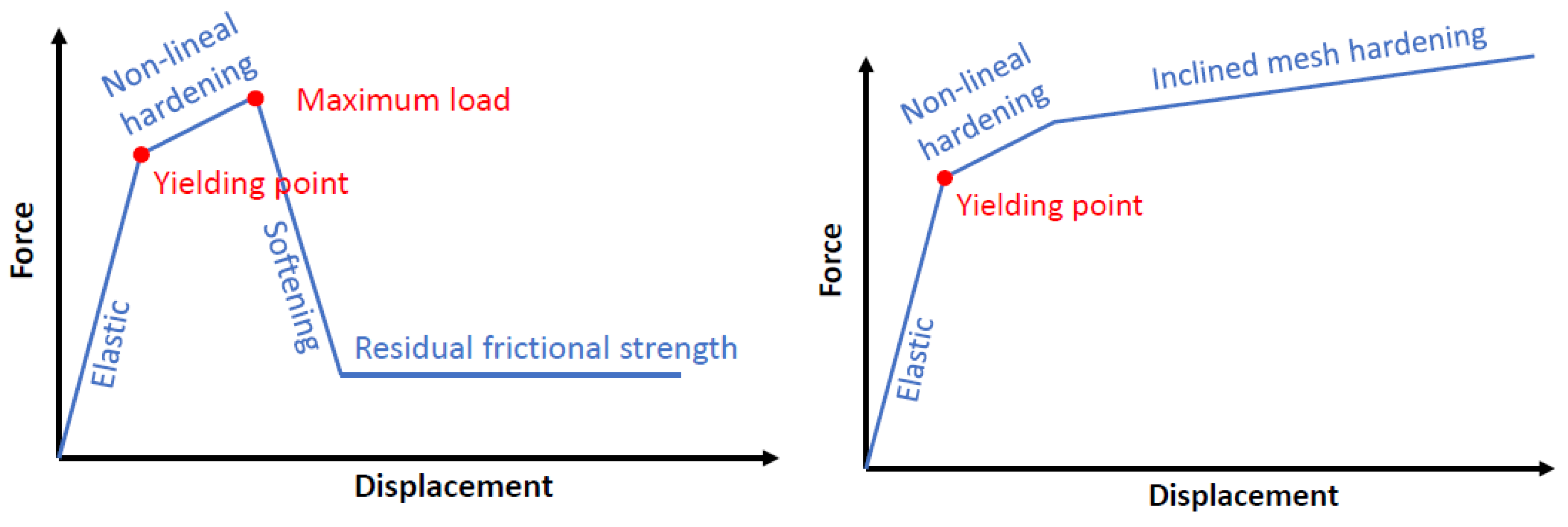
- Embedding a flexible structural glass fiber material as a connector between the CFRP sheet and the concrete increased the shear load-bearing capacity and enhanced the post-peak shear strength, changing the failure mode from sudden to progressive. Moreover, the system with the mesh connection could dissipate much more energy than that with the aggregate connection. The curve performance of the inclined mesh showed some similarities to a bolt connection.
- The numerical simulations combining a frictional model and the embedding of a fabric were capable of reproducing the experimental curves. Adjustment values must be taken with caution but are consistent with the results.
- The numerical model explains that the orientation of the fabric plays an important role in the structural response because of the possibility of combining two resisting strategies, axial and shear, when inclined with respect to the load direction.
- A real locking mechanism is a complex combination including concrete cracking, debonding of fibers and concrete, sliding of fibers, locking concrete in the grid gaps, friction between concrete and FRP, and breakage of fibers. The proposed strategy simplifies this complex combination of resisting mechanisms into only two equivalent interfaces: the frictional interface between concrete and FRP and the embedded beam elements between concrete, mesh, and FRP.
- The achieved level of load is less than that for a traditional bolt system but it has the advantage of not using steel connectors, and it involves a very simple manufacturing process for thinner slabs.
Author Contributions
Funding
Institutional Review Board Statement
Informed Consent Statement
Data Availability Statement
Acknowledgments
Conflicts of Interest
References
- Colajanni, P.; Recupero, A.; Ricciardi, G.; Spinella, N. Failure by corrosion in PC bridges: A case history of a viaduct in Italy. Int. J. Struct. Integr. 2016, 7. [Google Scholar] [CrossRef]
- Siddika, A.; al Mamun, M.A.; Ferdous, W.; Alyousef, R. Performances, challenges and opportunities in strengthening reinforced concrete structures by using FRPs—A state-of-the-art review. Eng. Fail. Anal. 2020, 111, 104480. [Google Scholar] [CrossRef]
- Naser, M.Z.; Hawileh, R.A.; Abdalla, J.A. Fiber-reinforced polymer composites in strengthening reinforced concrete structures: A critical review. Eng. Struct. 2019, 198, 109542. [Google Scholar] [CrossRef]
- Kunwar, B.; McEntee, V.; Pantelides, C.P. Seismic repair of deficient and code compliant bridge wall piers. Eng. Struct. 2021, 233, 111595. [Google Scholar] [CrossRef]
- Pham, T.M.; Hao, H. Review of Concrete Structures Strengthened with FRP Against Impact Loading. Structures 2016, 7, 59–70. [Google Scholar] [CrossRef]
- Zou, X.; Lin, H.; Feng, P.; Bao, Y.; Wang, J. A review on FRP-concrete hybrid sections for bridge applications. Compos. Struct. 2021, 262, 113336. [Google Scholar] [CrossRef]
- Hulatt, J.; Hollaway, L.; Thorne, A. The use of advanced polymer composites to form an economic structural unit. Constr. Build. Mater. 2003, 17, 55–68. [Google Scholar] [CrossRef]
- Hulatt, J.; Hollaway, L.; Thorne, A. Short Term Testing of Hybrid T Beam Made of New Prepreg Material. J. Compos. Constr. 2003, 7, 135–144. [Google Scholar] [CrossRef]
- Mieres, J.M.; Calvo, I.; Miravete, A.; Gutiérrez, E.; Shahidi, E.; López, C. Descripción de paso superior vehicular de la Autovía del Cantábrico realizado con materiales compuestos. Mater. Constr. 2006, 56, 81–86. [Google Scholar] [CrossRef][Green Version]
- Gutiérrez, E.; Primi, S.; Mieres, J.M.; Calvo, I. Structural Testing of a Vehicular Carbon Fiber Bridge: Quasi-Static and Short-Term Behavior. J. Bridg. Eng. 2008, 13, 271–281. [Google Scholar] [CrossRef]
- Hall, J.E.; Mottram, J.T. Combined FRP Reinforcement and Permanent Formwork for Concrete Members. J. Compos. Constr. 1998, 2, 78–86. [Google Scholar] [CrossRef]
- Bank, L.C. Properties of pultruded fiber reinforced plastic structural members. Transp. Res. Rec. 1989, 117–124. [Google Scholar]
- Neto, A.B.d.S.; la Rovere, H.L. Flexural stiffness characterization of fiber reinforced plastic (FRP) pultruded beams. Compos. Struct. 2007, 81, 274–282. [Google Scholar] [CrossRef]
- Roberts, T.M.; Al-Ubaidi, H. Flexural and Torsional Properties of Pultruded Fiber Reinforced Plastic I-Profiles. J. Compos. Constr. 2002, 6, 28–34. [Google Scholar] [CrossRef]
- Canning, L.; Hollaway, L.; Thorne, A.M. An investigation of the composite action of an FRP/concrete prismatic beam. Constr. Build. Mater. 1999, 13, 417–426. [Google Scholar] [CrossRef]
- Nordin, H.; Täljsten, B. Testing of hybrid FRP composite beams in bending. Compos. Part B Eng. 2004, 35, 27–33. [Google Scholar] [CrossRef]
- Wang, J.; Li, S.; Lü, Z. Calculation and experiments on ultimate bearing capacity of FRP-concrete composite beams based on single layer failure criteria. J. Southeast Univ. Natural Sci. Ed. 2013, 43, 952–956. [Google Scholar] [CrossRef]
- Di, J.; Cao, L.; Han, J. Experimental study on the shear behavior of GFRP-concrete composite beam connections. Materials 2020, 13, 1067. [Google Scholar] [CrossRef] [PubMed]
- Tureyen, A.K.; Frosch, R.J. Shear tests of FRP-reinforced concrete beams without stirrups. ACI Struct. J. 2002, 99, 427–434. [Google Scholar] [CrossRef]
- Maurizio, G.; Kypros, P.; Peter, W. Shear Resistance of FRP RC Beams: Experimental Study. J. Compos. Constr. 2006, 10, 464–473. [Google Scholar] [CrossRef]
- Alam, M.S.; Hussein, A. Size Effect on Shear Strength of FRP Reinforced Concrete Beams without Stirrups. J. Compos. Constr. 2013, 17, 507–516. [Google Scholar] [CrossRef]
- Dias, S.J.E.; Silva, J.R.M.; Barros, J.A.O. Flexural and shear strengthening of reinforced concrete beams with a hybrid CFRP solution. Compos. Struct. 2021, 256, 113004. [Google Scholar] [CrossRef]
- Hadhood, A.; Agamy, M.H.; Abdelsalam, M.M.; Mohamed, H.M.; El-Sayed, T.A. Shear strengthening of hybrid externally-bonded mechanically-fastened concrete beams using short CFRP strips: Experiments and theoretical evaluation. Eng. Struct. 2019, 201, 109795. [Google Scholar] [CrossRef]
- Siwowski, T.; Rajchel, M. Structural performance of a hybrid FRP composite—Lightweight concrete bridge girder. Compos. Part B Eng. 2019, 174, 107055. [Google Scholar] [CrossRef]
- Rajchel, M.; Kulpa, M.; Siwowski, T. Experimental Study on a Novel Shear Connection System for FRP-Concrete Hybrid Bridge Girder. Materials 2020, 13, 2045. [Google Scholar] [CrossRef] [PubMed]
- Zou, X.X.; Wang, J.Q. Experimental study on joints and flexural behavior of FRP truss-UHPC hybrid bridge. Compos. Struct. 2018, 203, 414–424. [Google Scholar] [CrossRef]
- Amir, F.; Trevor, S. Composite T-Beams Using Reduced-Scale Rectangular FRP Tubes and Concrete Slabs. J. Compos. Constr. 2006, 10, 172–181. [Google Scholar] [CrossRef]
- Elmahdy, A.; El-Hacha, R.; Shrive, N. Flexural behaviour of hybrid composite girders in bridge construction. In Proceedings of the 4th International Conference on FRP Composites in Civil Engineering, CICE 2008, Zurich, Switzerland, 22–24 July 2008. [Google Scholar]
- El-Hacha, R.; Chen, D. Behaviour of hybrid FRP-UHPC beams subjected to static flexural loading. Compos. Part B Eng. 2012, 43, 582–593. [Google Scholar] [CrossRef]
- El-Sayed, A.K.; Soudki, K. Evaluation of shear design equations of concrete beams with FRP reinforcement. J. Compos. Constr. 2011, 235, 112017. [Google Scholar] [CrossRef]
- Tavakkolizadeh, M.; Saadatmanesh, H. Repair of Damaged Steel-Concrete Composite Girders Using Carbon Fiber-Reinforced Polymer Sheets. J. Compos. Constr. 2003, 7, 311–322. [Google Scholar] [CrossRef]
- Zhang, P.; Hu, R.; Zou, X.; Liu, Y.; Li, Q.; Wu, G.; Sheikh, S.A. Experimental study of a novel continuous FRP-UHPC hybrid beam. Compos. Struct. 2021, 261, 113329. [Google Scholar] [CrossRef]
- Zhang, P.; Lv, X.; Liu, Y.; Zou, X.; Li, Y.; Wang, J.; Sheikh, S.A. Novel fiber reinforced polymers (FRP)-ultrahigh performance concrete (UHPC) hybrid beams with improved shear performance. Constr. Build. Mater. 2021, 286, 122720. [Google Scholar] [CrossRef]
- Al-Amery, R.I.M.; Roberts, T.M. Nonlinear finite difference analysis of composite beams with partial interaction. Comput. Struct. 1990, 35, 81–87. [Google Scholar] [CrossRef]
- Thevendran, V.; Chen, S.; Shanmugam, N.E.; Liew, J.Y.R. Nonlinear analysis of steel-concrete composite beams curved in plan. Finite Elem. Anal. Des. 1999, 32, 125–139. [Google Scholar] [CrossRef]
- Sebastian, W.M.; McConnel, R.E. Nonlinear FE analysis of steel-concrete composite structures. J. Struct. Eng. 2000, 126, 662–674. [Google Scholar] [CrossRef]
- Yang, J.Q.; Smith, S.T.; Wang, Z.; Lim, Y.Y. Numerical simulation of FRP-strengthened RC slabs anchored with FRP anchors. Constr. Build. Mater. 2018, 172, 735–750. [Google Scholar] [CrossRef]
- Kong, X.; Qi, X.; Gu, Y.; Lawan, I.A.; Qu, Y. Numerical evaluation of blast resistance of RC slab strengthened with AFRP. Constr. Build. Mater. 2018, 178, 244–253. [Google Scholar] [CrossRef]
- Ban, H.; Bradford, M.A. Flexural behaviour of composite beams with high strength steel. Eng. Struct. 2013, 56, 1130–1141. [Google Scholar] [CrossRef]
- Zheng, Y.; Yu, T.; Yang, J.; Li, Y.; Sun, C. Investigation of the behaviour of reinforcement-free concrete deck slabs restrained by FRP rods. Eng. Struct. 2017, 135, 191–208. [Google Scholar] [CrossRef]
- Mahboob, A.; Gil, L.; Bernat-Maso, E.; Eskenati, A.R. Flexible Fiber Fabric for FRP–Concrete Connection of Thin Hybrid Slabs. Polymers 2021, 13, 2862. [Google Scholar] [CrossRef]
- Gong, J.; Zou, X.; Shi, H.; Jiang, C.; Li, Z. Numerical investigation of the nonlinear composite action of FRP-concrete hybrid beams/decks. Appl. Sci. 2018, 8, 2031. [Google Scholar] [CrossRef]
- Gong, J.; Zou, X.; Xia, P. Experimental Investigation of the Natural Bonding Strength between Stay-In-Place Form and Concrete in FRP-Concrete Decks/Beams. Appl. Sci. 2019, 9, 913. [Google Scholar] [CrossRef]
- ASTM C805-02. Standard Test Method for Rebound Number of Hardened Concrete; ASTM Intermational: West Conshohocken, PA, USA, 2002. [Google Scholar] [CrossRef]
- ASTM D3039/D3039M-17. Standard Test Method for Tensile Properties of Polymer Matrix Composite Materials; ASTM Intermational: West Conshohocken, PA, USA, 2017. [Google Scholar] [CrossRef]
- Abaqus, “Dassault Systemes Simulia Corp. Abaqus v. 6.14-2 Analysis User’s Guide-Online Documentation; Dassault Systems: Vélizy-Villacoublay, France, 2014. [Google Scholar]
- Munoz, V.; Perrin, M.; Pastor, M.L.; Welemane, H.; Cantarel, A.; Karama, M. Determination of the elastic properties in CFRP composites: Comparison of different approaches based on tensile tests and ultrasonic characterization. Adv. Aircr. Spacecr. Sci. 2015, 2, 249–261. [Google Scholar] [CrossRef]
- European Committee. EN 1992-1-1 Eurocode 2: Design of Concrete Structures—Part 1-1: General Ruels and Rules for Buildings; European Committee: Brussels, Belgium, 2005. [Google Scholar]
- Elices, M.; Guinea, G.V.; Gómez, J.; Planas, J. The cohesive zone model: Advantages, limitations and challenges. Eng. Fract. Mech. 2002, 69, 137–163. [Google Scholar] [CrossRef]
- Schellart, W.P. Shear test results for cohesion and friction coefficients for different granular materials: Scaling implications for their usage in analogue modelling. Tectonophysics 2000, 324, 1–16. [Google Scholar] [CrossRef]


| Name | Aggregates | Straight Mesh (0°) | Inclined Mesh (45°) | Compressive Strength (MPa) |
|---|---|---|---|---|
| N-1 | - | - | - | 22.0 |
| N-2 | - | - | - | 22.6 |
| A-1 | Y | - | - | 18.9 |
| A-2 | Y | - | - | 19.0 |
| A-SM-1 | Y | Y | - | 19.0 |
| A-SM-2 | Y | Y | - | 20.8 |
| A-IM-1 | Y | - | Y | 20.0 |
| A-IM-2 | Y | - | Y | 21.0 |
| Material | Young’s Modulus (MPa) | Poisson’s Coefficient |
|---|---|---|
| Concrete | 29,975 | 0.20 |
| CFRP | 45,500 | 0.26 |
| Glass Fabric | 72,000 | 0.30 |
Publisher’s Note: MDPI stays neutral with regard to jurisdictional claims in published maps and institutional affiliations. |
© 2021 by the authors. Licensee MDPI, Basel, Switzerland. This article is an open access article distributed under the terms and conditions of the Creative Commons Attribution (CC BY) license (https://creativecommons.org/licenses/by/4.0/).
Share and Cite
Mahboob, A.; Gil, L.; Bernat-Maso, E.; Eskenati, A.R. Experimental and Numerical Study of Shear Interface Response of Hybrid Thin CFRP–Concrete Slabs. Materials 2021, 14, 5184. https://doi.org/10.3390/ma14185184
Mahboob A, Gil L, Bernat-Maso E, Eskenati AR. Experimental and Numerical Study of Shear Interface Response of Hybrid Thin CFRP–Concrete Slabs. Materials. 2021; 14(18):5184. https://doi.org/10.3390/ma14185184
Chicago/Turabian StyleMahboob, Amir, Lluís Gil, Ernest Bernat-Maso, and Amir Reza Eskenati. 2021. "Experimental and Numerical Study of Shear Interface Response of Hybrid Thin CFRP–Concrete Slabs" Materials 14, no. 18: 5184. https://doi.org/10.3390/ma14185184
APA StyleMahboob, A., Gil, L., Bernat-Maso, E., & Eskenati, A. R. (2021). Experimental and Numerical Study of Shear Interface Response of Hybrid Thin CFRP–Concrete Slabs. Materials, 14(18), 5184. https://doi.org/10.3390/ma14185184