
Sacrificial Cladding with Brittle Materials for Blast Protection


Abstract
:1. Introduction
- Material toughness T: integration of the stress/strain evolution corresponding to the energy dissipated by the cellular material under compression;
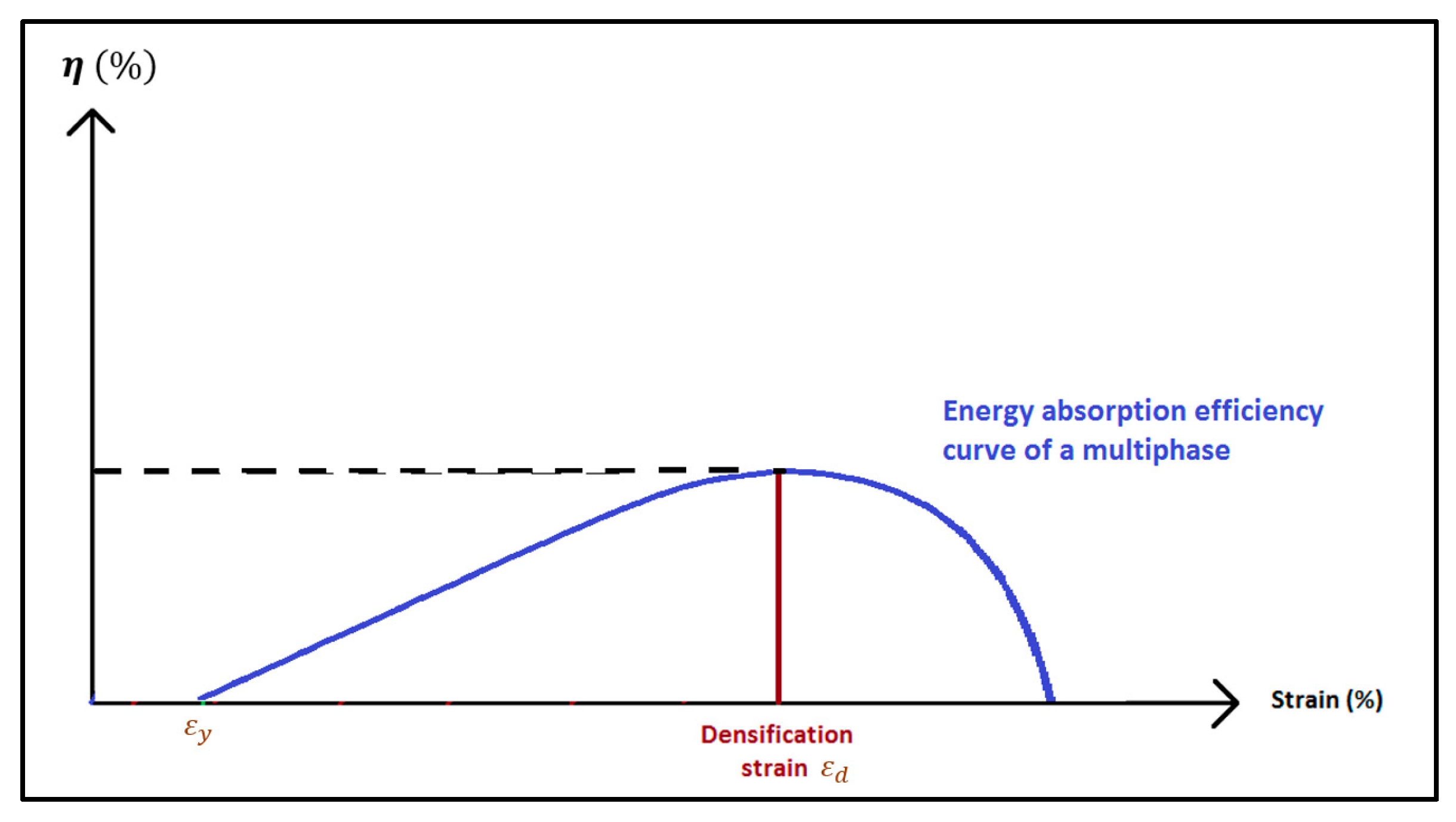
- Plateau Stress σ0: quasi constant transmitted load between the end of the elastic phase of the material εy and the beginning of its densification phase εd;
- Densification strain εd: strain at which the struts and plates of the cellular material come into contact, leading to the densification of the sample. It provides information on the thickness necessary to avoid the rise of the stress during the densification process. P0.
2. Materials and Methods
2.1. Methodology
- for 15 g of C4: ΔPi = 7.99 bars, Ii = 3.09 bars.ms, ti = 1.28 ms. Based on the UFC 3-340-02 [27], these effects are equivalent to those of 17.3 kg of TNT placed 2.8 m away from the target;
- for 30 g of C4: ΔPi = 14.29 bars, Ii = 5.15 bars.ms, ti = 1.52 ms. These effects are equivalent to those of 87 kg of TNT placed 3.3 m away from the target;
- for 50 g of C4: ΔPi = 22.53 bars, Ii = 7.42 bars.ms, ti = 1.61 ms. These effects are equivalent to those of 567 kg of TNT placed 4.72 m away from the target.
- for 15 g of C4: ΔPr = 38.72 bars, Ir = 16.98 bars.ms, tr = 3.22 ms;
- for 30 g of C4: ΔPr = 79.69 bars, Ir = 26.54 bars.ms, tr = 3.36 ms;
- for 50 g of C4: ΔPr = 131.55 bars, Ir = 39.76 bars.ms, tr = 3.42 ms.
- With the sensor, the load versus time curve F(t) can be plotted, and with the video recording, the time of maximum front plate displacement is known. The transmitted impulse Itrans to the target can be calculated with Equation (1) and can be compared with the transmitted impulse to the front plate:
- The load versus time curve F(t) gained from the sensor, and the displacement versus time curve l(t) gained from the video recording, are cross-referenced in order to calculate the load-displacement curve F(l) of the material. Knowing the surface Asample and thickness hsample of the sample, it can be converted into the stress–strain curve σ(ε) similar to the one shown Figure 2.
- The energy Eabs absorbed by the sample before reaching the densification is calculated using Equation (2).
- The toughness T of the material can then be calculated with Equation (4). By definition, this is the total energy per unit volume a sample can dissipate before densification.
- Firstly, all of the material parameters calculated above are strain-rate dependent. It has been shown in the literature that for most materials, the higher the strain-rate, the higher the plateau stress and the lower the densification strain.
- Secondly, this experimental set-up only allows to study the macroscopic behavior of the core, hence this analytical approach. While it is not originally designed for granular materials, it is assumed that the deformation and densification of the granular media will be similar to those of cellular materials and the following methodology should be applied. To the best of the author‘s knowledge, there is no alternative at this time.
- Lastly, it is not possible to know prior to the test the quantity of energy transmitted to the core. In a sacrificial cladding, the blast wave energy is converted into kinetic energy which is then dissipated by the core. However, the energy transmitted to the system is dependent on the system itself. Since the front plate is not projected on the core, a stronger core will react strongly against the displacement of the front plate and limit its acceleration. In fine, this experimental set-up allows the characterization of a system composed of the front plate and the core, but does not allow the characterization of the core alone, as a drop tower would do. This peculiar approach has already been used for investigating blast protection because it allows to take into account the full phenomenology of the blast interaction with the structure and the blast loading profile [4,7,24], making it closer to practical application. However, this set-up could be used more traditionally by projecting the front plate on the sample, like a horizontal drop tower focusing on velocity instead of weight. Such approach is not discussed in this paper but can be used to estimate the maximal kinetic energy which could be transfer to the core. For a 652 g steel plate, its maximal kinetic energy under a 50 g solicitation would be close to 476 J.
2.2. Test Samples
- Aluminum Hexagonal Honeycomb (ρ = 40 kg/m3): this core acts as a reference due to its inherent efficiency for energy dissipation through plastic deformation.
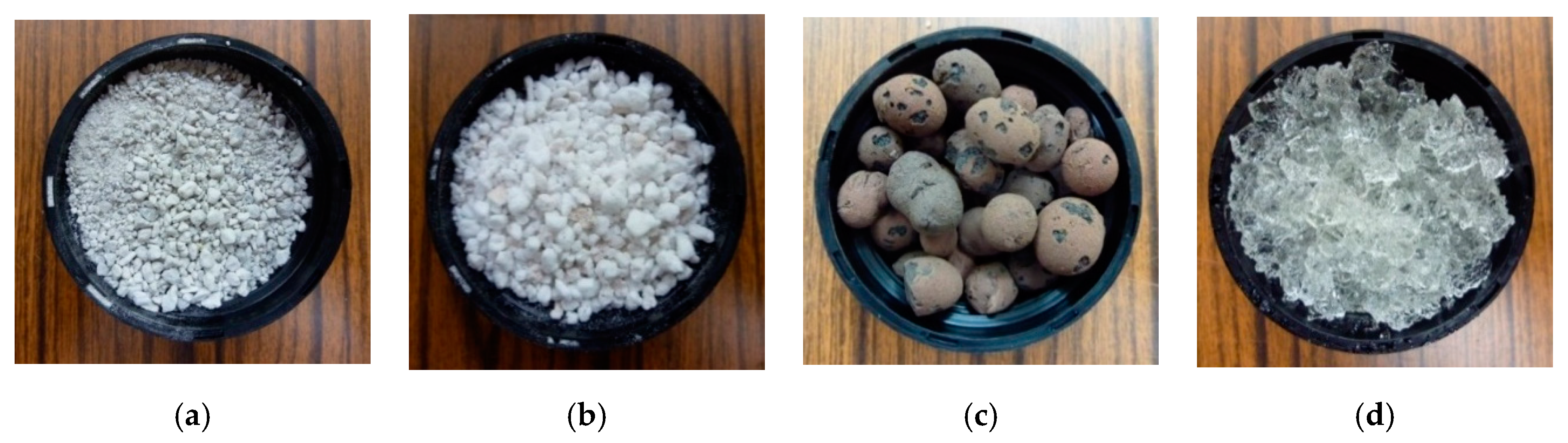
- Pumice (ρ = 910 kg/m3), Perlite (ρ = 120 kg/m3), and Clay Ball (ρ = 680 kg/m3): presented Figure 8, these granular media are able to act as a potential crushable core thanks to the brittle deformations and displacement of their grains.
- Hydrogel (ρ = 616 kg/m3): the polymer consists of 10% of Crosslinked Copolymer Acrylamide—Potassium Acrylate powder (APRODEV™ 06, APROTEK, Saint-Romain-le-Puy, France) and 90% water. In comparison to the previous materials, this granular media should present an elasto-plastic behavior.
- Concrete foam (from 150 to 700 kg/m3): this brittle cellular material is compared with the previous brittle granular materials.
3. Results
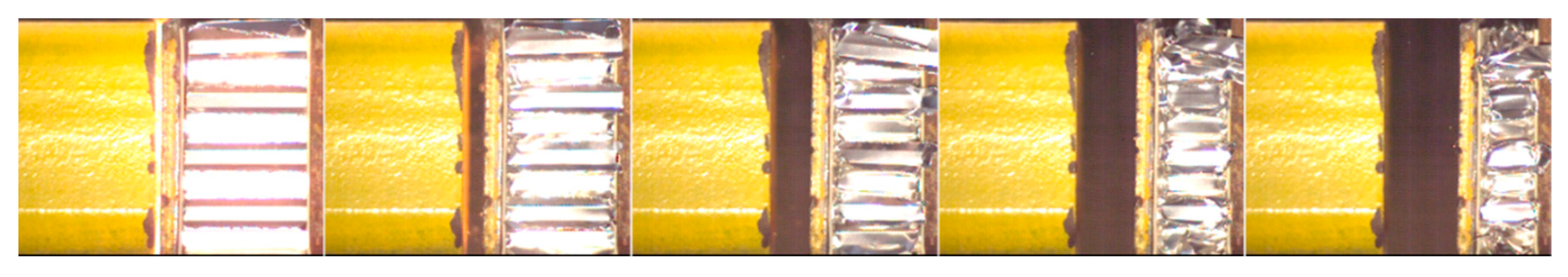
3.1. Honeycomb
3.2. Concrete Foam
- On the low density sample, the applied forced is enough to start the fractures near the front plate. The sample weakens, decreases its reaction against the front plate displacement. From this point onward, the concrete foam is crushed progressively, dissipating a total of 231 J. A slight densification near a 90% strain is estimated. Compared to honeycomb, this value is particularly high, and can be explained by the concrete dust and chunks expulsed from under the plate. This is not possible with an elasto-plastic material, where most of the material of the deformed sample will act against the displacement of the front plate.
- On the contrary, the collapse stress on the densest sample is not reached with the applied solicitation. A compressive wave is sent through the sample and is reflected at its end against the rigid wall, leading to an increase of the stress at the bottom of the sample. This stress is high enough to start fracturing the sample from its end, but is insufficient to completely crush the sample.
3.3. Brittle Granular Materials
4. Discussion
5. Conclusions
Author Contributions
Funding
Institutional Review Board Statement
Informed Consent Statement
Data Availability Statement
Conflicts of Interest
References
- Breda, C.; Kerampram, S.; Sturtzer, M.-O.; Arrigoni, M.; Legendre, J.-F. Experimental Study of Blast and Shock Wave Mitigation by Wet Aqueous Foams. In Proceedings of the 23rd MABS—Military Aspects of Blast and Shock, Oxford, UK, 7–12 September 2014. [Google Scholar]
- Schunck, T.; Bastide, M.; Eckenfels, D.; Legendre, J.-F. Blast mitigation by water mist: The effect of the detonation configuration. Shock. Waves 2020, 30, 629–644. [Google Scholar] [CrossRef]
- Sochet, I.; Eveillard, S.; Vinçont, J.Y.; Piserchia, P.F.; Rocourt, X. Influence of the geometry of protective barriers on the propagation of shock waves. Shock. Waves 2017, 27, 209–219. [Google Scholar] [CrossRef] [Green Version]
- Hanssen, A.; Enstock, L.; Langseth, M. Close-range blast loading of aluminium foam panels. Int. J. Impact Eng. 2002, 27, 593–618. [Google Scholar] [CrossRef]
- Langdon, G.; Karagiozova, D.; Theobald, M.; Nurick, G.; Lu, G.; Merrett, R. Fracture of aluminium foam core sacrificial cladding subjected to air-blast loading. Int. J. Impact Eng. 2010, 37, 638–651. [Google Scholar] [CrossRef]
- Li, X.; Zhang, P.; Wang, Z.; Wu, G.; Zhao, L. Dynamic behavior of aluminum honeycomb sandwich panels under air blast: Experiment and numerical analysis. Compos. Struct. 2014, 108, 1001–1008. [Google Scholar] [CrossRef]
- Ding, Y.; Zheng, Y.; Zheng, Z.; Wang, Y.; He, S.; Zhou, F. Blast Alleviation of Sacrificial Cladding with Graded and Uniform Cellular Materials. Materials 2020, 13, 5616. [Google Scholar] [CrossRef] [PubMed]
- Kambouchev, N.; Noels, L.; Radovitzky, R. Nonlinear compressibility effects in fluid-structure interaction and their implications on the air-blast loading of structures. J. Appl. Phys. 2006, 100, 063519. [Google Scholar] [CrossRef]
- Maiti, S.; Gibson, L.; Ashby, M. Deformation and energy absorption diagrams for cellular solids. Acta Met. 1984, 32, 1963–1975. [Google Scholar] [CrossRef]
- Gibson, L.J.; Ashby, M.F. Cellular Solids: Structure and Properties, 2nd ed.; Cambridge University Press: Cambridge, UK, 2014. [Google Scholar] [CrossRef]
- Bhate, D. Four Questions in Cellular Material Design. Materials 2019, 12, 1060. [Google Scholar] [CrossRef] [Green Version]
- Ouellet, S.; Cronin, D.; Worswick, M. Compressive response of polymeric foams under quasi-static, medium and high strain rate conditions. Polym. Test. 2006, 25, 731–743. [Google Scholar] [CrossRef]
- Whisler, D.; Kim, H. Experimental and simulated high strain dynamic loading of polyurethane foam. Polym. Test. 2015, 41, 219–230. [Google Scholar] [CrossRef]
- Koohbor, B.; Kidane, A.; Lu, W.-Y. Characterizing the constitutive response and energy absorption of rigid polymeric foams subjected to intermediate-velocity impact. Polym. Test. 2016, 54, 48–58. [Google Scholar] [CrossRef] [Green Version]
- Raj, R.E.; Parameswaran, V.; Daniel, B. Comparison of quasi-static and dynamic compression behavior of closed-cell aluminum foam. Mater. Sci. Eng. A 2009, 526, 11–15. [Google Scholar] [CrossRef]
- Merrett, R.; Langdon, G.; Theobald, M. The blast and impact loading of aluminium foam. Mater. Des. 2013, 44, 311–319. [Google Scholar] [CrossRef]
- Stöbener, K.; Lehmhus, D.; Avalle, M.; Peroni, L.; Busse, M. Aluminum foam-polymer hybrid structures (APM aluminum foam) in compression testing. Int. J. Solids Struct. 2008, 45, 5627–5641. [Google Scholar] [CrossRef]
- Theobald, M.; Langdon, G.; Nurick, G.; Pillay, S.; Heyns, A.; Merrett, R. Large inelastic response of unbonded metallic foam and honeycomb core sandwich panels to blast loading. Compos. Struct. 2010, 92, 2465–2475. [Google Scholar] [CrossRef]
- Theobald, M.; Nurick, G. Experimental and numerical analysis of tube-core claddings under blast loads. Int. J. Impact Eng. 2010, 37, 333–348. [Google Scholar] [CrossRef]
- Palanivelu, S.; Van Paepegem, W.; Degrieck, J.; De Pauw, S.; Vantomme, J.; Wastiels, J.; Kakogiannis, D.; Van Hemelrijck, D. Low velocity axial impact crushing performance of empty recyclable metal beverage cans. Int. J. Impact Eng. 2011, 38, 622–636. [Google Scholar] [CrossRef] [Green Version]
- Ramamurthy, K.; Nambiar, E.K.; Ranjani, G.I.S. A classification of studies on properties of foam concrete. Cem. Concr. Compos. 2009, 31, 388–396. [Google Scholar] [CrossRef]
- Flores-Johnson, E.A.; Li, Q. Structural behaviour of composite sandwich panels with plain and fibre-reinforced foamed concrete cores and corrugated steel faces. Compos. Struct. 2012, 94, 1555–1563. [Google Scholar] [CrossRef] [Green Version]
- Tian, X.; Li, Q.; Lu, Z.; Wang, Z. Experimental study of blast mitigation by foamed concrete. Int. J. Prot. Struct. 2016, 7, 179–192. [Google Scholar] [CrossRef]
- Langhorst, B.; Cook, C.; Schondel, J.; Chu, H.S. Material Systems for Blast Energy Dissipation. In Proceedings of the IMPLAST 2010, Providence, RI, USA, 12–14 October 2010. [Google Scholar]
- Ousji, H.; Belkassem, B.; Louar, M.; Reymen, B.; Martino, J.; Lecompte, D.; Pyl, L.; Vantomme, J. Air-blast response of sacrificial cladding using low density foams: Experimental and analytical approach. Int. J. Mech. Sci. 2017, 128–129, 459–474. [Google Scholar] [CrossRef]
- Yang, C. An adaptive sensor placement algorithm for structural health monitoring based on multi-objective iterative optimization using weight factor updating. Mech. Syst. Signal. Process. 2021, 151, 107363. [Google Scholar] [CrossRef]
- Department of Defense. UFC 3-340-02: Structures to Resist the effect of Accidental Explosions; Department of Defense: Washington, DC, USA, 2008. [Google Scholar]
- Li, Q.M.; Magkiriadis, I.; Harrigan, J.J. Compressive Strain at the Onset of Densification of Cellular Solids. J. Cell. Plast. 2006, 42, 371–392. [Google Scholar] [CrossRef]
- Valore, R.C. Cellular concretes Part 2 Physical Properties. J. Proc. 1954, 50, 817–836. [Google Scholar]
- Aldridge, D. Introduction to foamed concrete What Why and How. In Use of Foamed Concrete in Construction; ICE Publishing: London, UK, 2005; pp. 1–14. [Google Scholar]
- Hamidah, M.S.; Azmi, I.; Ruslan, M.R.A.; Kartini, K.; Fadhil, N.M. Optimisation of foamed concrete mix of different sand-cement ratio and curing condition. In Use of Foamed Concrete in Construction; ICE Publishing: London, UK, 2005. [Google Scholar]
- Yoshimoto, N.; Hyodo, M.; Nakata, Y.; Orense, R.; Hongo, T.; Ohnaka, A. Evaluation of shear strength and mechanical properties of granulated coal ash based on single particle strength. Soils Found. 2012, 52, 321–334. [Google Scholar] [CrossRef] [Green Version]
- Wood, D.M.; Maeda, K. Changing grading of soil: Effect on critical states. Acta Geotech. 2008, 3, 3–14. [Google Scholar] [CrossRef]
- Altuhafi, F.; Coop, M. Changes to particle characteristics associated with the compression of sands. Géotechnique 2011, 61, 459–471. [Google Scholar] [CrossRef]
- Lade, P.V.; Bopp, P.A. Relative density effects on drained sand behavior at high pressures. J. Jpn. Geotech. Soc. 2005, 45, 1–13. [Google Scholar] [CrossRef]
- Oda, M.; Nemat-Nasser, S.; Mehrabadi, M.M. A statistical study of fabric in a random assembly of spherical granules. Int. J. Numer. Anal. Methods Géoméch. 1982, 6, 77–94. [Google Scholar] [CrossRef]
- Xiao, Y.; Liu, H.; Ding, X.; Chen, Y.; Jiang, J.; Zhang, W. Influence of Particle Breakage on Critical State Line of Rockfill Material. Int. J. Géoméch. 2016, 16, 04015031. [Google Scholar] [CrossRef]
- Hurley, R.; Lind, J.; Pagan, D.; Akin, M.; Herbold, E. In situ grain fracture mechanics during uniaxial compaction of granular solids. J. Mech. Phys. Solids 2018, 112, 273–290. [Google Scholar] [CrossRef]
- Alshibli, K.A.; Jarrar, M.F.; Druckrey, A.M.; Al-Raoush, R.I. Influence of Particle Morphology on 3D Kinematic Behavior and Strain Localization of Sheared Sand. J. Geotech. Geoenviron. Eng. 2017, 143, 04016097. [Google Scholar] [CrossRef]
- Kirkpatrick, D.; Argyle, A.; Harrison, K.; Leggett, J.; Elert, M.; Furnish, M.D.; Chau, R.; Holmes, N.; Nguyen, J. A Comparison of the Blast & Fragment Mitigation Performance of Several Structurally Weak Materials. In Shock Compression of Condensed Matter 2007, Proceedings of the Conference of the American Physical Society Topical Group on Shock Compression of Condensed Matter, Waikoloa, Hawaii, 24–29 June 2007; AIP Publishing: Melville, NY, USA, 2008; Volume 955, pp. 951–954. [Google Scholar]
- Bornstein, H.A. Physical Mechanisms for Near-Field Blast Mitigation with Fluid-Filled Containers. Ph.D. Thesis, RMIT University, Melbourne, VIC, Austalia, 2018. [Google Scholar]


| Crushable Core | C4 (g) | Front Plate (g) | Densification | εd (-) | σ0 (kPa) | T (kJ·m−3) | Eabs (J) | |
|---|---|---|---|---|---|---|---|---|
| Honeycomb 40 kg·m−3 | 50 | 652 | Yes | 0.71 | 661 | 564 | 282 | |
| 30 | 652 | No | >0.60 | 626 | >244 | 142 | ||
| 15 | 652 | No | >0.43 | 607 | >133 | 67 | ||
| Perlite 120 kg·m−3 | 50 | 652 | Yes | 0.47 | 631 | 294 | 147 | |
| 30 | 652 | Yes | 0.51 | 304 | 135 | 68 | ||
| 15 | 652 | Yes | 0.35 | 222 | 79 | 39 | ||
| Clay Ball 680 kg·m−3 | 50 | 652 | No | >0.46 | 1881 | >670 | 335 | |
| 30 | 652 | No | >0.29 | 1404 | >307 | 153 | ||
| 15 | 652 | No | >0.20 | 963 | >170 | 85 | ||
| Pumice 910 kg·m−3 | 50 | 652 | No | >0.32 | 2262 | >226 | 113 | |
| 30 | 652 | No | >0.17 | 1880 | >187 | 93 | ||
| 15 | 652 | No | >0.10 | 663 | >49 | 25 | ||
| Hydrogel 616 kg·m−3 | 50 | 652 | Yes | n/a | 734 | n/a | n/a | |
| 30 | 652 | Yes | n/a | 450 | n/a | n/a | ||
| 15 | 652 | No | n/a | 159 | n/a | n/a | ||
| Concrete foam | 700 kg·m−3 | 50 | 652 | No Crushing | Full transmission | |||
| 400 kg·m−3 | 50 | 652 | No Crushing | Full transmission | ||||
| 400 kg·m−3 | 50 | 224 | No | n/a | 2000 | n/a | n/a | |
| 150 kg·m−3 | 50 | 652 | Yes | n/a | 230 | n/a | n/a | |
Publisher’s Note: MDPI stays neutral with regard to jurisdictional claims in published maps and institutional affiliations. |
© 2021 by the authors. Licensee MDPI, Basel, Switzerland. This article is an open access article distributed under the terms and conditions of the Creative Commons Attribution (CC BY) license (https://creativecommons.org/licenses/by/4.0/).
Share and Cite
Blanc, L.; Schunck, T.; Eckenfels, D. Sacrificial Cladding with Brittle Materials for Blast Protection. Materials 2021, 14, 3980. https://doi.org/10.3390/ma14143980
Blanc L, Schunck T, Eckenfels D. Sacrificial Cladding with Brittle Materials for Blast Protection. Materials. 2021; 14(14):3980. https://doi.org/10.3390/ma14143980
Chicago/Turabian StyleBlanc, Ludovic, Thérèse Schunck, and Dominique Eckenfels. 2021. "Sacrificial Cladding with Brittle Materials for Blast Protection" Materials 14, no. 14: 3980. https://doi.org/10.3390/ma14143980
APA StyleBlanc, L., Schunck, T., & Eckenfels, D. (2021). Sacrificial Cladding with Brittle Materials for Blast Protection. Materials, 14(14), 3980. https://doi.org/10.3390/ma14143980