1. Introduction
Alumina (Al
2O
3) ceramics have numerous valuable properties, including high thermal conductivity, high insulation and strength, and low thermal expansion coefficient. As such, Esmail et al. and Wang et al. expressed that they are often used as preferred materials for medium- and high-end electronic substrates in both the aerospace and information technology industries [
1,
2]. To achieve the high-density electronic system interconnection, it is usually required to process the holes located on the Al
2O
3 ceramics surface, making the double-sided lines connected based on THVF (Through Hole Via Filling). Therefore, high quality hole processing is very necessary, demonstrating none or little spatter, recast layer, burr, crack, and good roundness, etc. However, traditional machining methods have a high rejection rate and low processing efficiency due to the Al
2O
3 hardness and brittleness. Comparatively, laser drilling with high peak energy is among the best hole machining methods for ceramics substrates. Liu et al. and Zhao et al. summarized that the advantages for laser drilling are non-contact processing, lack of tool loss, high efficiency and precision, among others [
3,
4].
Considering the pulse duration, they mainly include millisecond laser, nanosecond laser, and ultrafast laser hole processing on electronic ceramic substrate. Firstly, many studies on millisecond pulse laser machining ceramics substrate are available; Mei et al. reviewed its processing mechanism is primarily the thermal effect with the thermal stress and soma chemical reactions [
5], meaning that the processing quality is not ideal. Hanon et al. and Kacar et al. discussed the hole ablation by using millisecond pulse laser in Al
2O
3 ceramic, it can be seen from the top and profile figures of holes, there are dozens or even hundreds of micron surface spatters and side-wall recast [
6,
7]. In recent years, the short and ultra-short pulse laser technology was developed rapidly, and the related studies on its use for machining ceramic substrates were carried out. For example, Nedialkov et al. studied the N and O element contents in the heat-affected zone in detail, and the related chemical reaction mechanism [
8,
9]. Mutlu et al. found the average hole diameter and depth increase with the laser average power increasing [
10]. Additionally, the ablation depth per pulse increased as the laser fluence increasing but slowly because of the plasma shielding effect [
11]. Kong et al. reported the hole depth increased through adding the fluence, or minishing the repetition rate and scanning speed in both air and water [
12]. For the ultrafast laser, Kim et al. [
13], Li et al. [
14], Chen et al. [
15], Wang et al. [
16], and Kim et al. [
17] observed the laser drilling of Al
2O
3 and ALN ceramics using femtosecond pulses. Relationships between the processing parameters, the fluence/energy, number of pulses, focus position, and hole diameter/depth, ablation rate, were discussed. Besides, there is little or no spatters around the periphery of hole, a small amount of recast layer on side-wall, thinner and shorter cracks for short and ultrashort pulses of laser hole processing on ceramics [
9,
14,
16,
17]. In general, holes with higher quality can be produced for short and ultrafast laser than millisecond laser. However, the nanosecond laser is much cheaper than ultrafast laser, and generally offers the best cost-efficient. Therefore, the exploration on nanosecond laser ceramic hole machining has the most practical value.
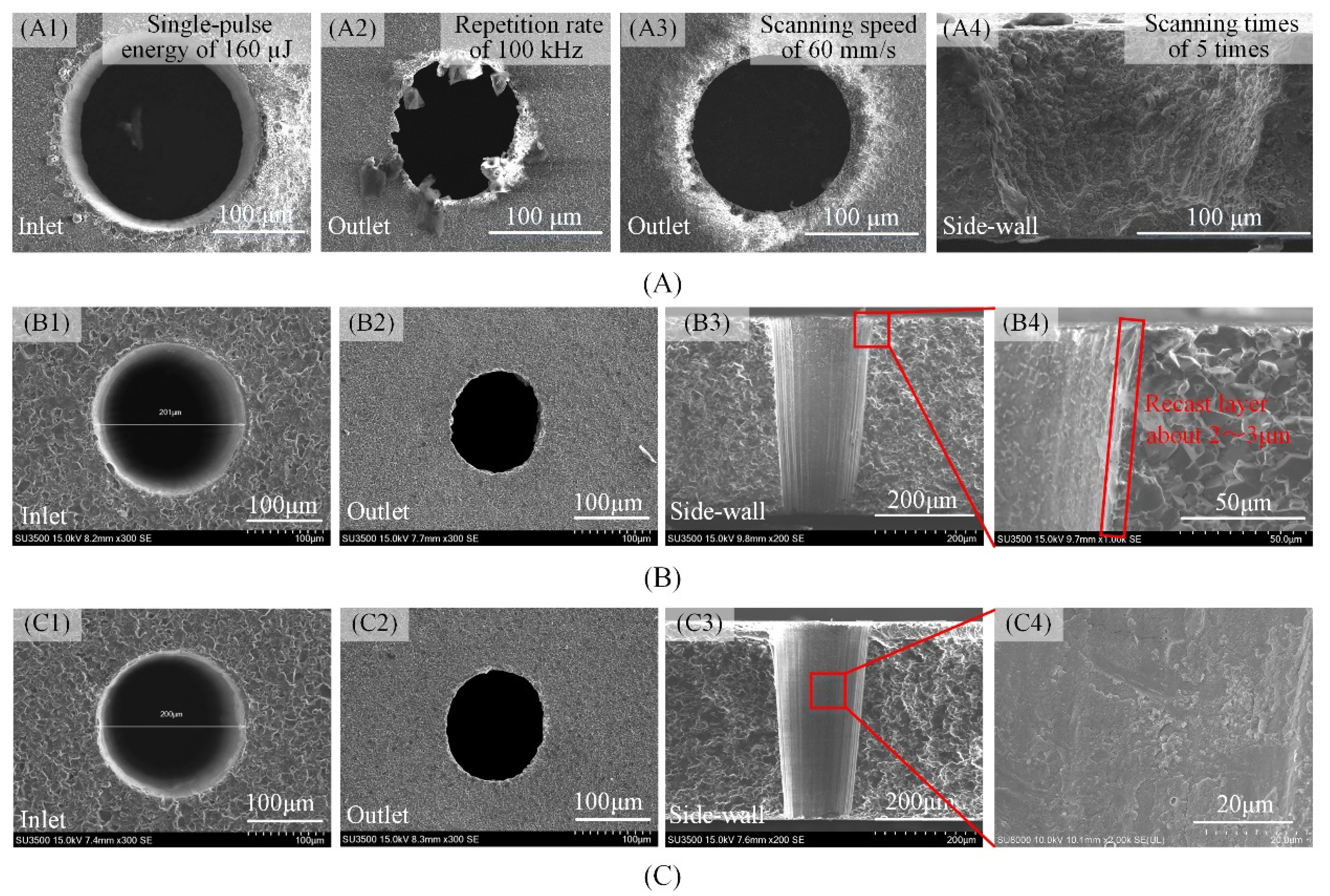
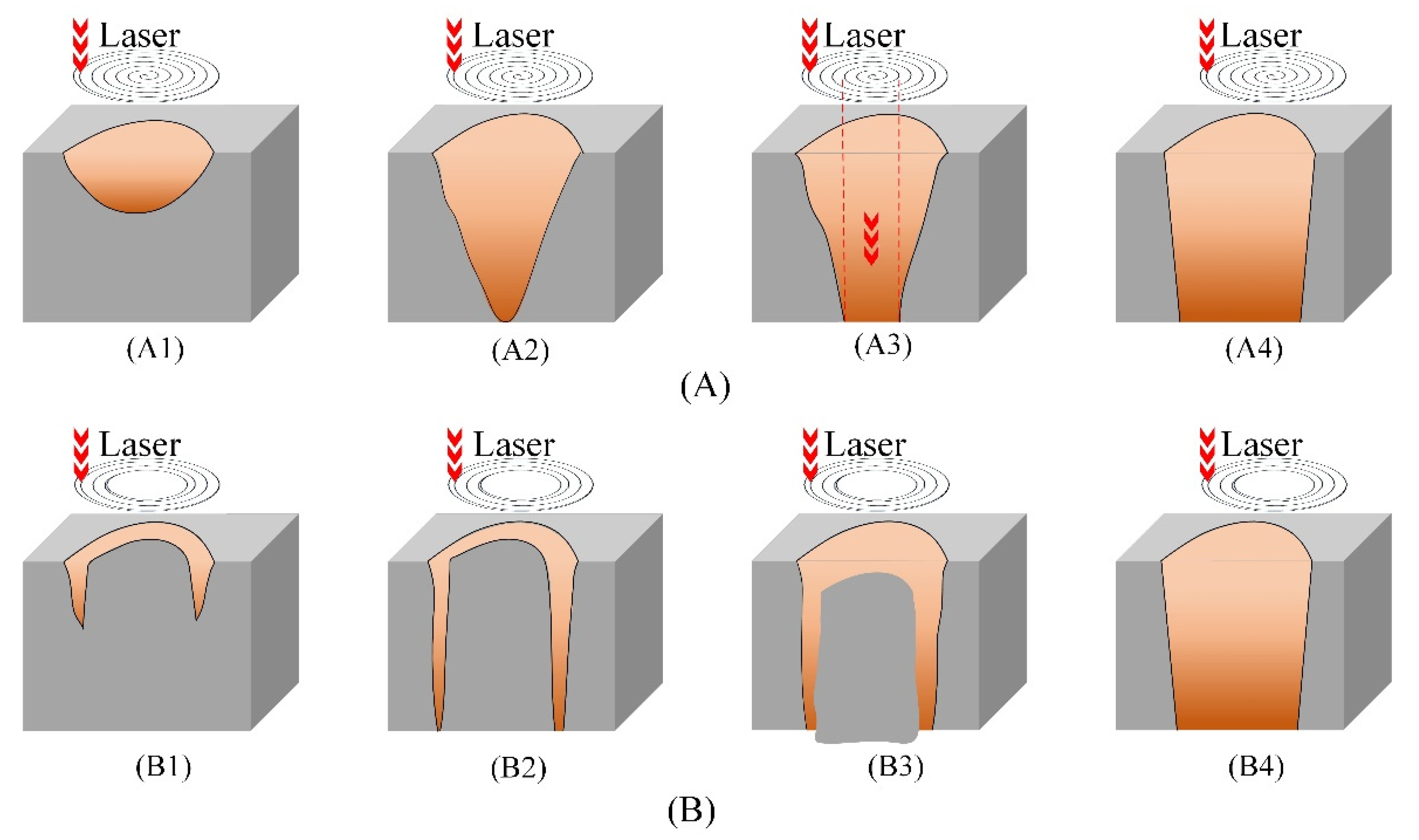
Considering the hole ablation strategies, laser percussion drilling has been the most frequently used method for the general ablation of holes with a diameter below 100 μm. On the other hand, laser trepanning, being a percussion drilling process followed by a cutting procedure [
18], is the most commonly employed process for larger diameter holes. Such as, Ashkenasi et al. reported the laser trepanning holes with the entrance diameters of 90 to 150 μm in stainless steel and ALN ceramic samples for industrial applications [
19]. There are two main characteristics for laser trepanning. One, the sample upper surface coincides with the laser focal plane and remains unchanged, the other, the cutting paths or trepanning patterns are mainly filled with concentric circles, spiral and single or multiple rings and so on, the laser beam is scanned along with the designed trepanning patterns, removing the material, thus drilling holes. Furthermove, the trepanning patterns are very important. Thanking the Zhao et al. research for example, it had been found that the hole side-wall quality was better when the scanning direction was from the inside to the outside, and the ratio between the filling distance and the laser waist diameter was ranging from 2/9 and 1/3, for nanosecond laser trepanning filled with concentric circles patterns on ALN ceramics [
20]. Compared with the most commonly used trepanning patterns concentric circles and spiral patterns, the research on single or multiple rings trepanning patterns is less. Wang et al. compared three different drilling methods, percussion drilling, single-ring cutting, and spiral trepanning, and found that the spiral trepanning method should be adopted for the film hole machining with the hole diameter larger than 100 µm in the K24 superalloy, for single-ring cutting, chip removal will be more and more difficult, and the surface chip will be heated repeated forming of heavy recasting and thermal effect areas [
21]. Relatively, there are some advantages for multiple rings trepanning. Wang et al. [
16] and Kim et al. [
17] researched the variations in hole machining quality and the efficiency for both a single circle and three circle trepanning. The smaller tapers, improved hole circularity, and higher machining efficiency were observed in three circle trepanning, suggesting the great potential but less research.
Based on the literature review, it can be concluded that the optimization of trepanning patterns is indeed effective, but very few studies were carried out on the subject. Thus, in this study, the effects of two laser trepanning patterns based on the UV nanosecond pulse, filled spiral trepanning and multiple rings trepanning, on the hole quality and efficiency in Al2O3 ceramics was studied. The optimization of trepanning patterns based on both machining quality and efficiency was carried out for the industry-standard Al2O3 ceramics with the common hole diameters.
2. Experiments and Materials
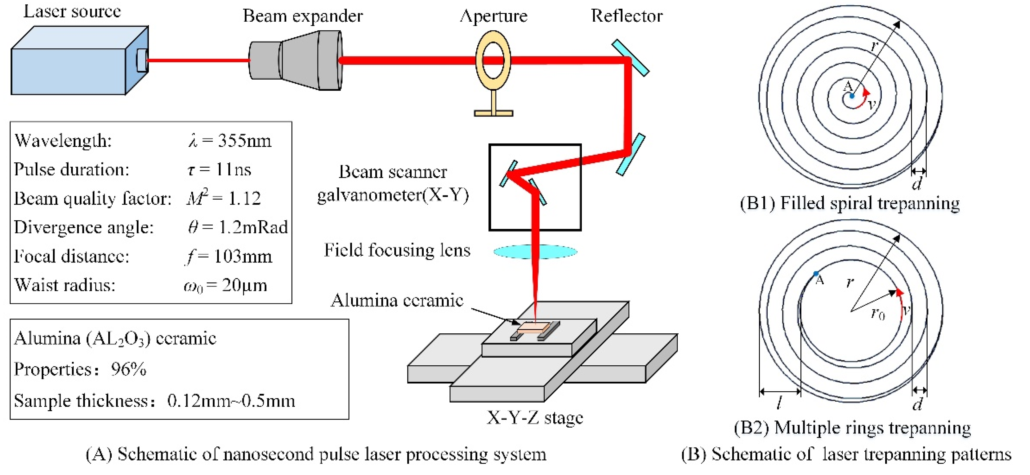
Figure 1A illustrates the nanosecond pulse laser drilling system, which includes the UV nanosecond pulse laser, the optical path transmission, the focusing system, the precise movement platform, and the control system. The las Diode Pumped Solid State (DPSS) Q-switched laser Fotia-355 with the laser wavelength λ of 355 nm was used in the experiment. The pulse duration
τ was 11 ns, while the repetition rate
f was 50 kHz. Moreover, the laser beam diameter was 1.1 mm, with a nominal beam ellipticity of 97.1%. The beam quality factor was
M2 = 1.12, and its divergence angle was1.2 mRad. Generally, the beam energy conforms to the Gaussian distribution. Finally, the laser beam focusing spot diameter was approximately 20 μm and was transmitted and focused by the focusing field mirror with a focal length of 103 mm.
Two laser trepanning patterns were studied in this article to obtain high quality and efficiency hole machining, filled spiral trepanning and multiple rings trepanning (see
Figure 1B). Characteristic parameters for both patterns are the ex-radius
r, which has a major influence on the inlet diameter, and gap fills
d. In trepanning with multiple rings, specific parameters are the in-radius
r0 and the ring width
l. It should also be noted that the laser beam path is taken from inside to outside, where
v is the scanning speed. Once the first scan is finished, the laser beam moves to the starting position point A, and the second scan is started. Using that analogy, the scanning was completed
n times.
Additionally, the experiments were carried out under ambient conditions. After the experiment, the scanning electron microscope (SEM), optical microscope (OM), and laser confocal microscope (LCM) were used to observe the hole morphologies and dimensions. Five holes were drilled using the same processing parameters, allowing to find the average value. The hole diameter was found through Equation (1):
where
D is the average hole diameter,
Dmax and
Dmin are the long and short axes of the hole center diameter, respectively.
The hole circularity
C is equal to the ratio between the short
Dmin and the long axis diameter
Dmax, calculated by Equation (2) [
22,
23]:
Additionally, the hole taper
α is calculated as [
24]:
where
Den and
Dex are the hole inlet and outlet diameters, respectively, and
h is the material thickness (hole depth).
In the experiment, 96% Al2O3 ceramics was used; test specimen length and width were 100 mm. Sample thicknesses were as follows: 0.12, 0.25, 0.38, and 0.5 mm, while the target machining inlet diameters were ranging from 100 to 1500 µm. It should be noted that those sample thicknesses and ablated inlet diameters are the most widely used as commercial ceramic electronic substrates. Lastly, before the experiment samples were cleaned using the ultrasonic for 10 min in combination with acetone and anhydrous ethanol. After the cleaning, samples were placed on a precision moving worktable.
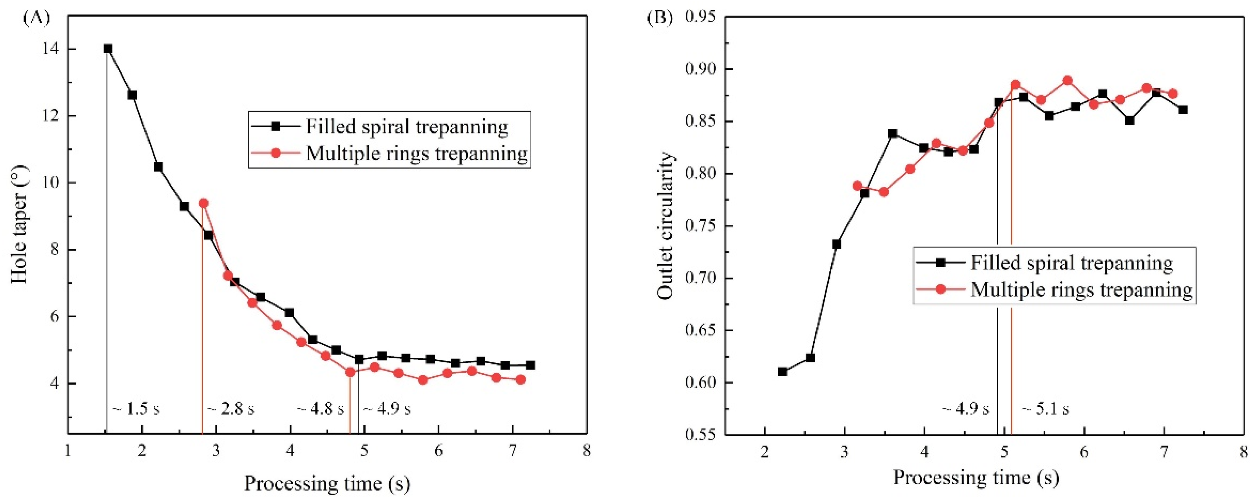
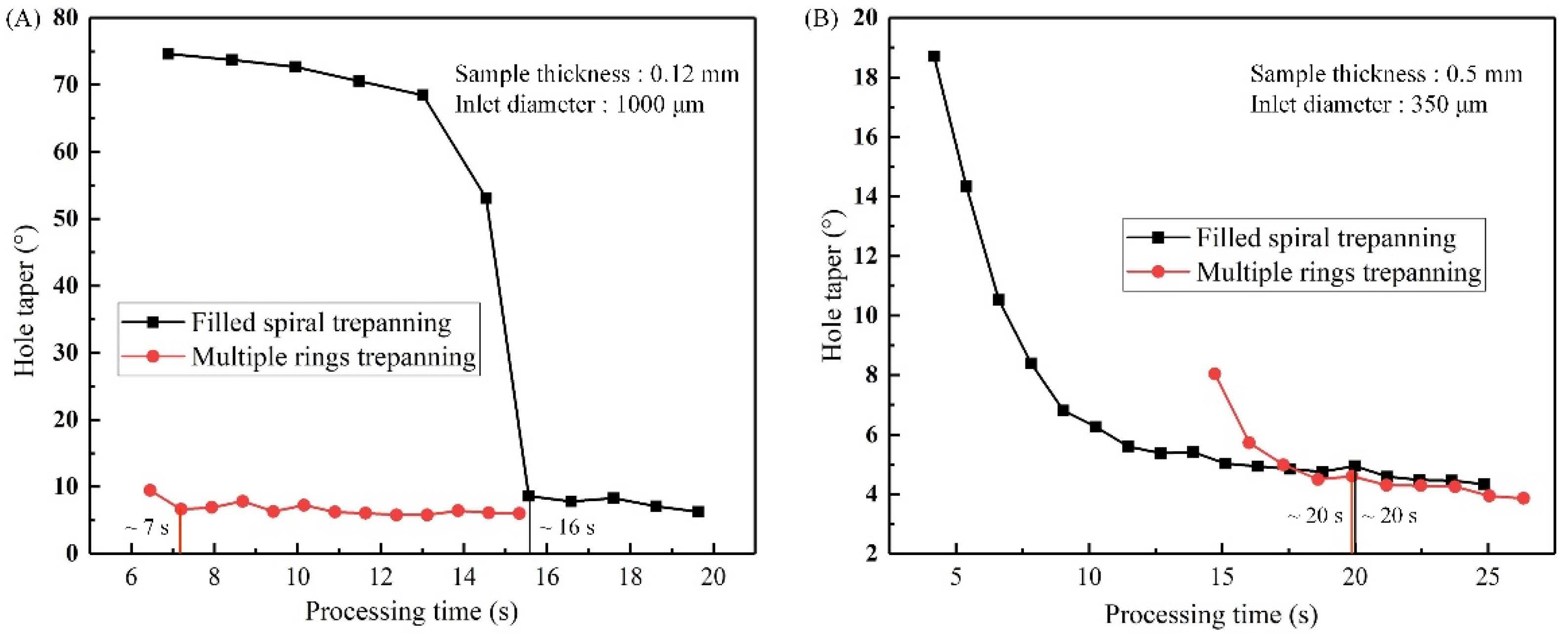
4. Comparison of Hole Quality and Machining Efficiency
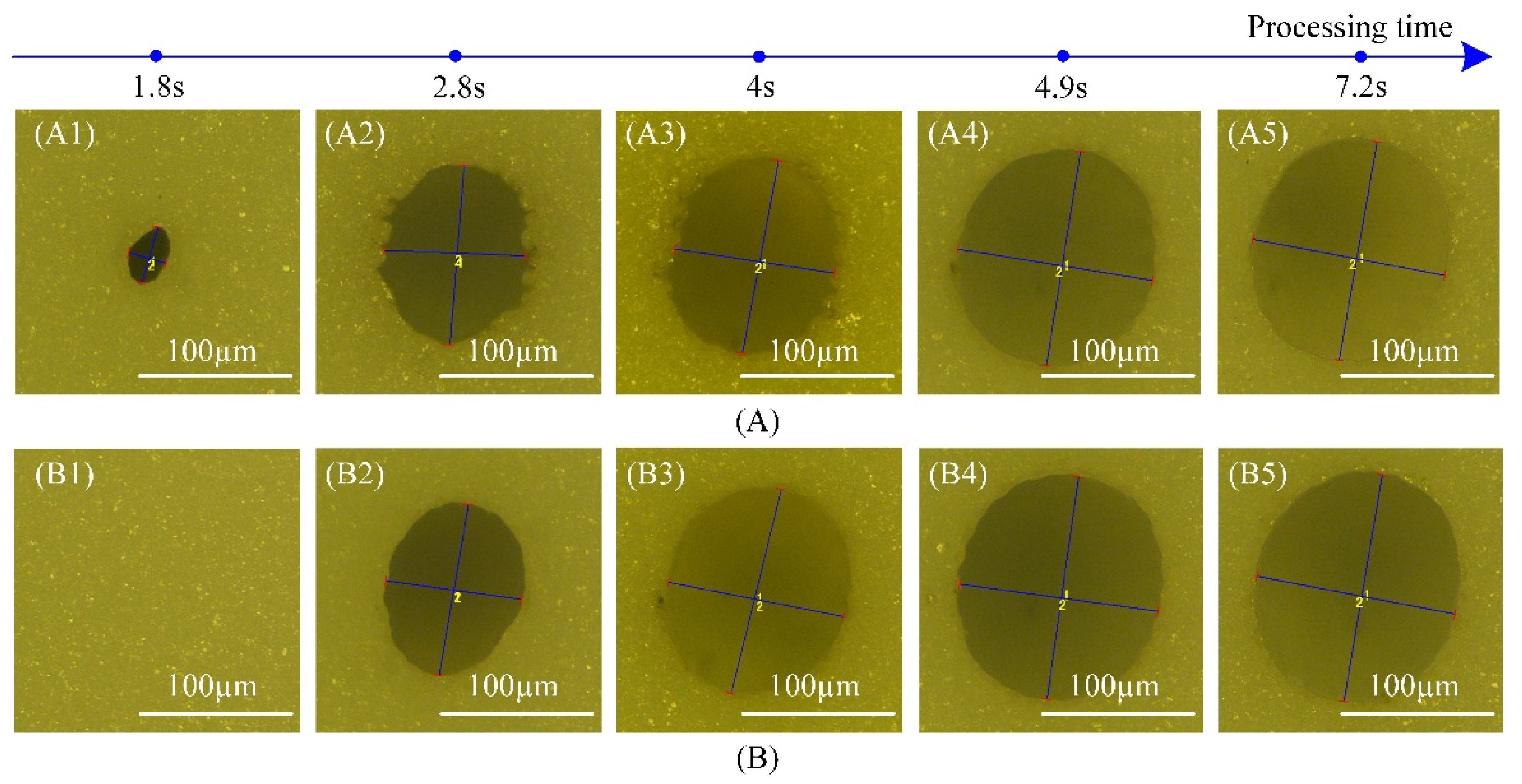
The hole machining efficiencies obtained by two laser trepanning patterns using the optimized laser machining parameters were analyzed and compared. The processing time needed to reach the saturated state (saturated processing time) was used as the evaluation criterion. The hole quality has reached the best values for the results shown in
Section 3.1. Moreover,
Figure 8 shows the relationship between the hole taper and the processing time for both trepanning patterns. The sample thickness was 0.12 mm and the inlet diameter was 1000 μm in
Figure 8A, and they were 0.5 mm and 350 μm in
Figure 8B. It is evident that the saturated processing times ablated by filled spiral laser trepanning and the multiple rings laser trepanning were approximately 16 and 7 s (see
Figure 8A), and roughly 20 s (
Figure 8B). For the hole processing shown in
Figure 8A, saturated processing times (hole machining efficiencies) based on multiple rings laser trepanning were about twice the filled spiral laser trepanning values. On the other hand, in
Figure 8B, the multiple rings laser trepanning time is almost the same with the filled spiral laser trepanning time.
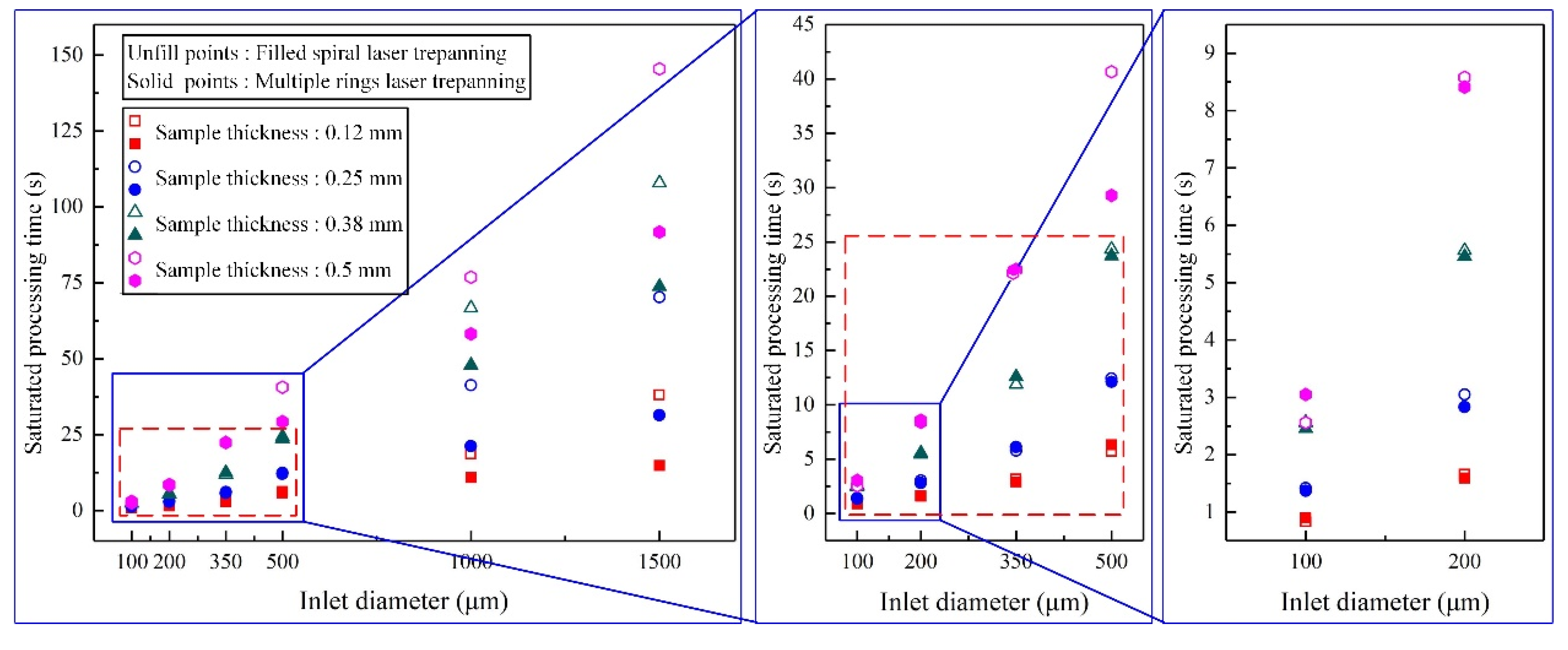
Figure 9 shows the saturated hole processing times ablated using nanosecond pulse laser in Al
2O
3 ceramics. When the inlet diameters were above 1000 μm with 0.12 to 0.38 mm thick samples, and the above 500 μm in 0.5 mm thick samples, the saturated hole processing times were longer for filled spiral laser trepanning (
Figure 9). In other words, the multiple rings laser trepanning had higher efficiency. When the inlet diameters were below 350 μm for all the considered sample thicknesses, and when the inlet diameters were below 500 μm in 0.12 to 0.38 mm thick samples, the saturated hole processing times were similar for both methods, as shown in the red dotted boxes (
Figure 9). Thus, in that case, the processing efficiencies were rather similar.
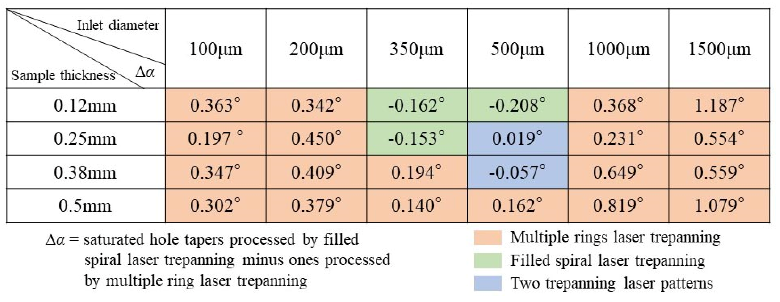
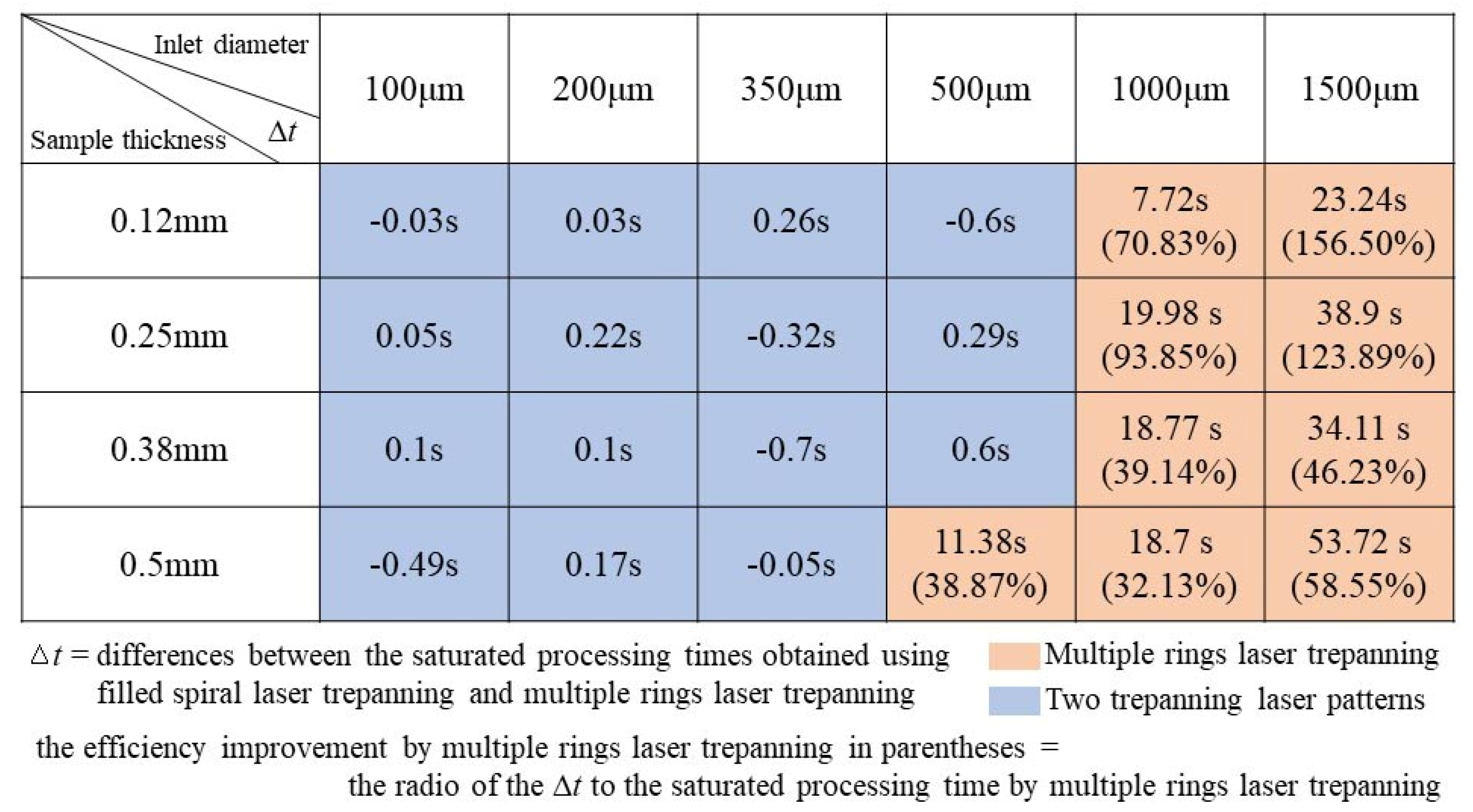
The data in
Figure 10 show the differences in the saturated processing times ∆
t, which are defined as the differences between the saturated processing times obtained using the filled spiral laser trepanning and the multiple rings laser trepanning. When the ∆
t above zero, the saturated processing time needed by filled spiral laser trepanning is longer, meaning that the multiple rings trepanning laser should be selected (the orange area in
Figure 10). Taking the minimum and maximum ∆
t values (the orange area of
Figure 10) as examples; the 7.72 s for 0.12 mm thickness and 1000 μm inlet diameter, and 53.72 s for 0.5 mm thickness and 1500 μm inlet diameter. The saturated processing time for the minimum ∆
t by filled spiral laser trepanning and multiple rings laser trepanning are 18.62 and 10.9 s, respectively. For the maximum, they are 145.47 and 91.75 s, respectively. Compared to the machining efficiency by filled spiral laser trepanning, the efficiency improvement achieved by the use of multiple rings trepanning is 70.83% and 58.55%, respectively. The efficiency improvement obtained by multiple rings trepanning ranges from 32.13% to 156.50% (see
Figure 10). For the remaining combinations, these values are below 1 s (the blue area in
Figure 10), meaning that there is a minor difference in the processing efficiencies between two laser trepanning patterns. Therefore, both methods can be used effectively.
5. Conclusions
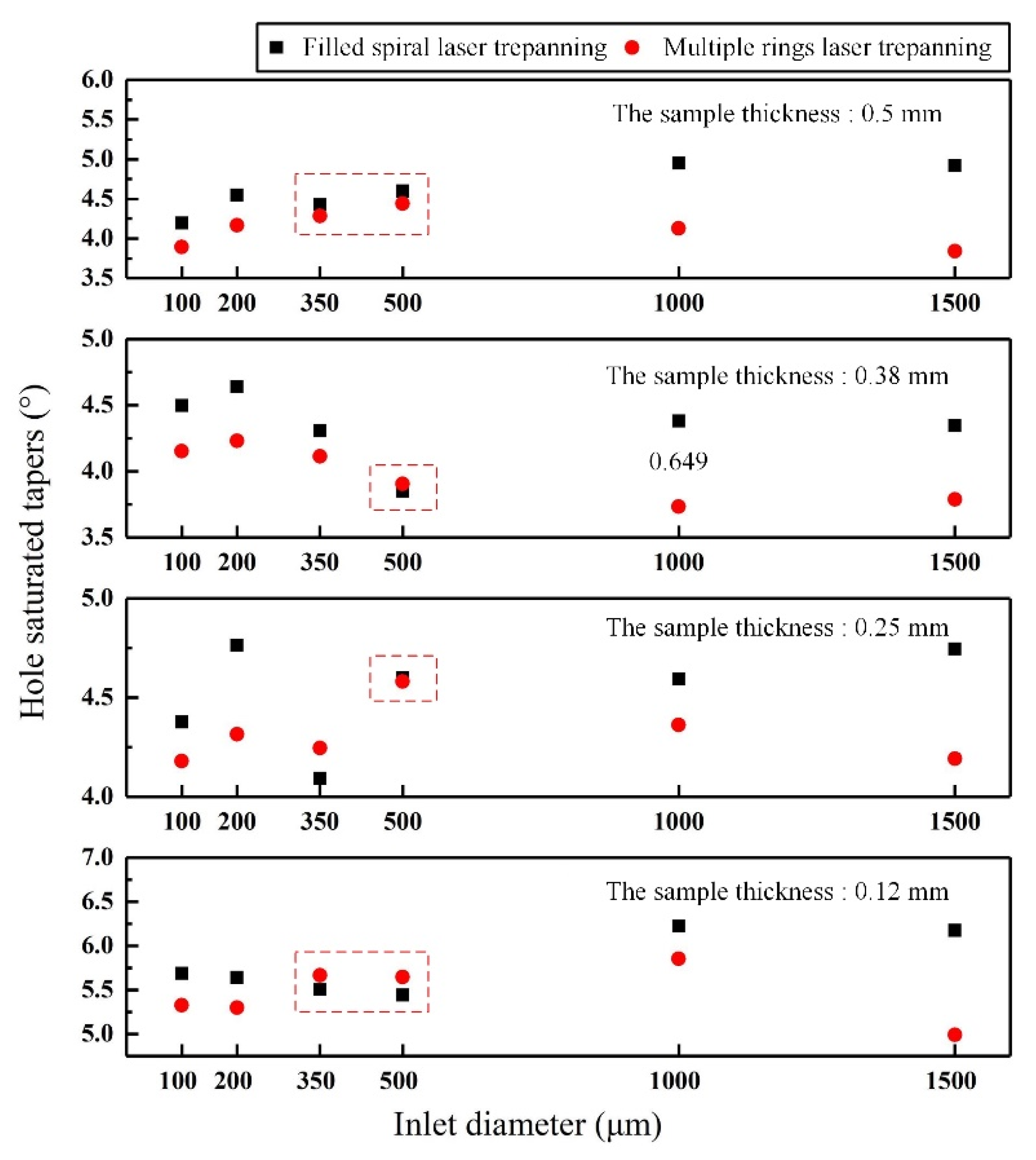
The influence of two laser trepanning patterns used in the UV nanosecond pulse filled spiral trepanning and multiple rings trepanning, on the hole quality and efficiency was studied. The test specimens were made of Al2O3 ceramics of industry-standard substrate thicknesses (between 0.12 and 0.5 mm), while the common hole diameters were between 100 and 1500 µm. The main criteria used to evaluate the hole quality and the machining efficiency were the saturated hole taper and the saturated processing time, respectively.
The research has shown that, for obtaining the high hole quality, the inlet diameters were below 200 μm or above 1000 μm for all the studied sample thicknesses, furthermore, the inlet diameter was 350 μm for the sample thicknesses between 0.38 and 0.5 mm and 500 μm for the 0.5 mm sample thickness, the results were satisfying for the multiple rings trepanning.
In filled spiral trepanning, when the inlet diameter was 350 μm for sample thicknesses ranging from 0.12 to 0.25 mm, and 500 μm for the 0.12 mm sample thickness. The results were considered to be satisfying. Furthermore, when the inlet diameter was 500 μm, sample thicknesses were between 0.25 and 0.38 mm, justifying the use of both laser trepanning patterns.
Regarding the hole quality and processing efficiency, when the inlet diameters were above 1000 μm and the sample thicknesses between 0.12 and 0.38 mm, and the inlet diameters above 500 μm in combination with the sample thickness of 0.5 mm, multiple rings trepanning provided good results. The efficiency improvement when using multiple rings trepanning was thus ranging from 32.13% to 156.50%. Furthermore, when the inlet diameters were below 350 μm and the sample thicknesses ranged between 0.12 and 0.5 mm, as well as the inlet diameters below 500 μm with the sample thicknesses between 0.12 and 0.38 mm, both laser trepanning patters provided good results.


