
Microstructure and Properties of TiB2 Composites Produced by Spark Plasma Sintering with the Addition of Ti5Si3

 ,
,  , , and
Abstract
:1. Introduction
2. Materials and Methods
2.1. Powders, Powder Mixtures and Parameters of Their Homogenization
2.2. Spark Plasma Sintering
2.3. Relative Density, Microstructure Examination
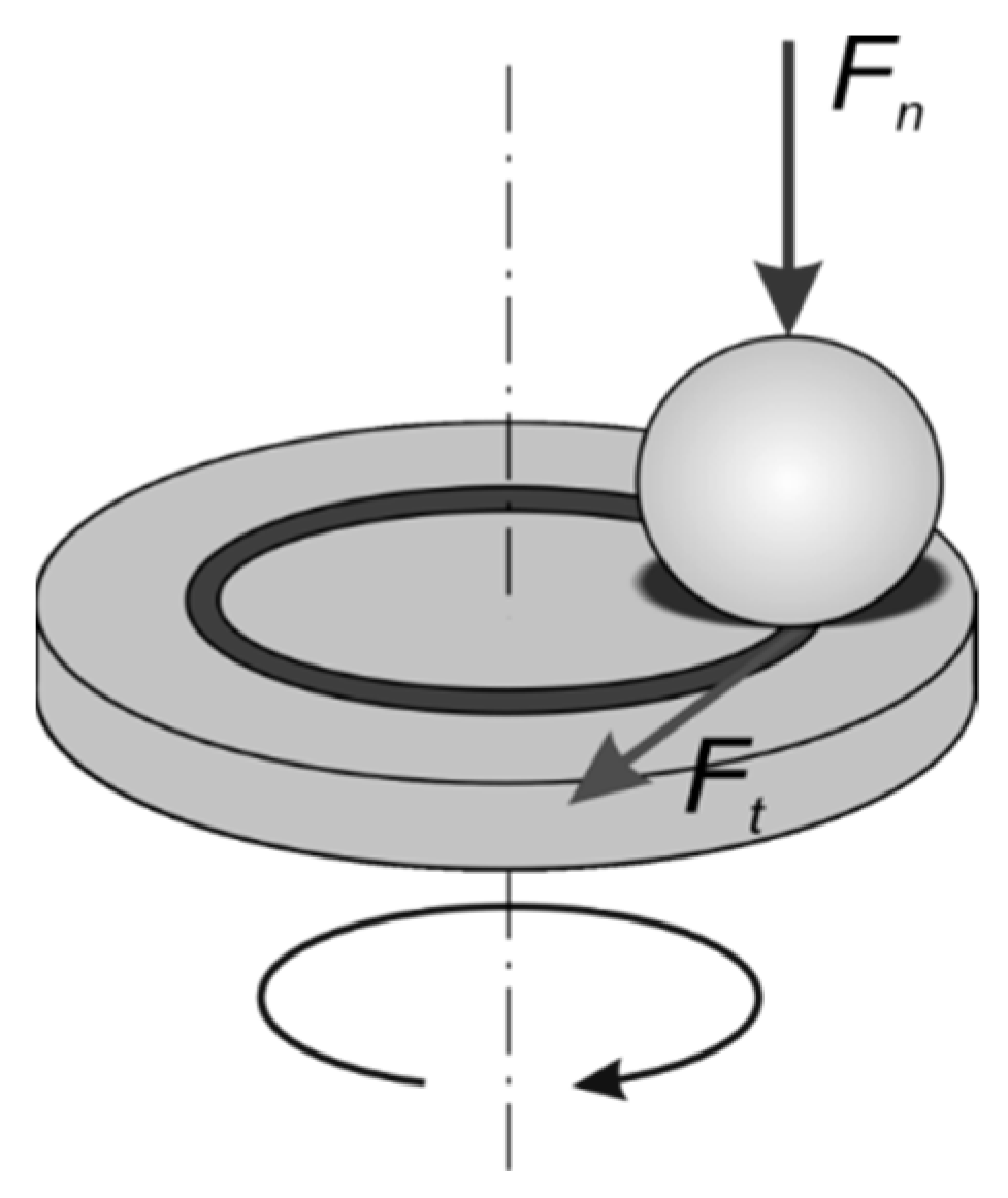
2.4. Hardness and Friction–Wear Tests
3. Results
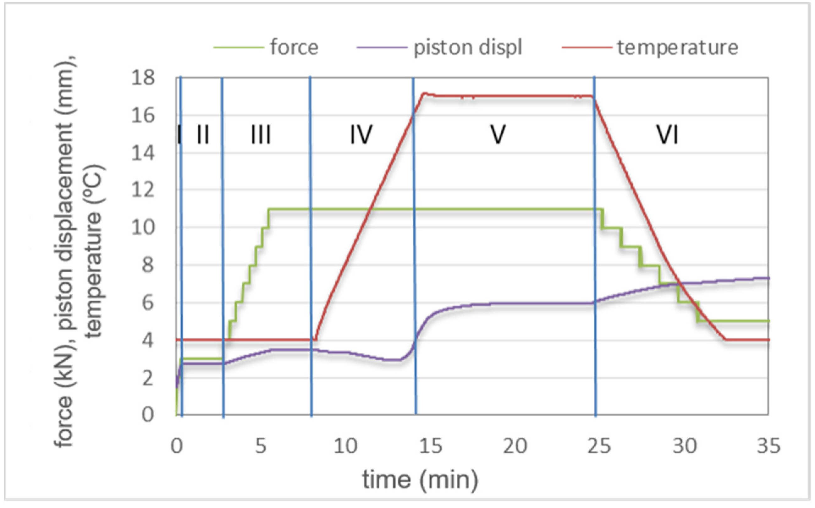
3.1. SPS Sintering
3.2. Relative Density
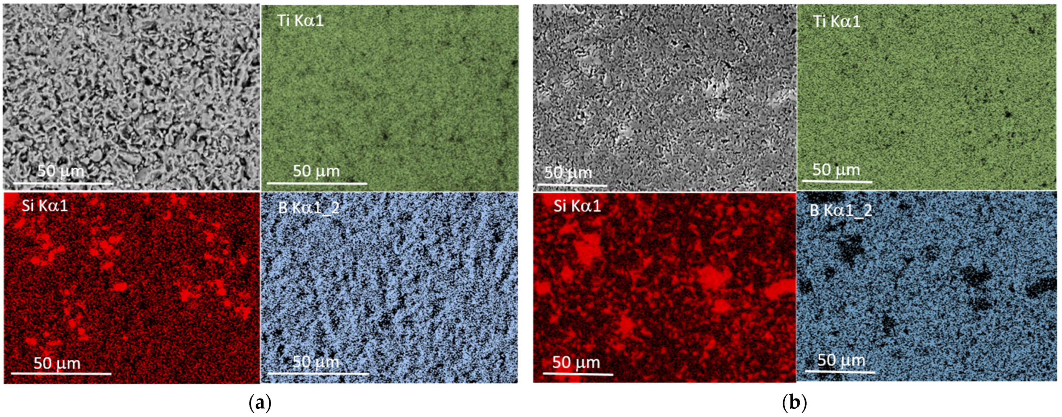
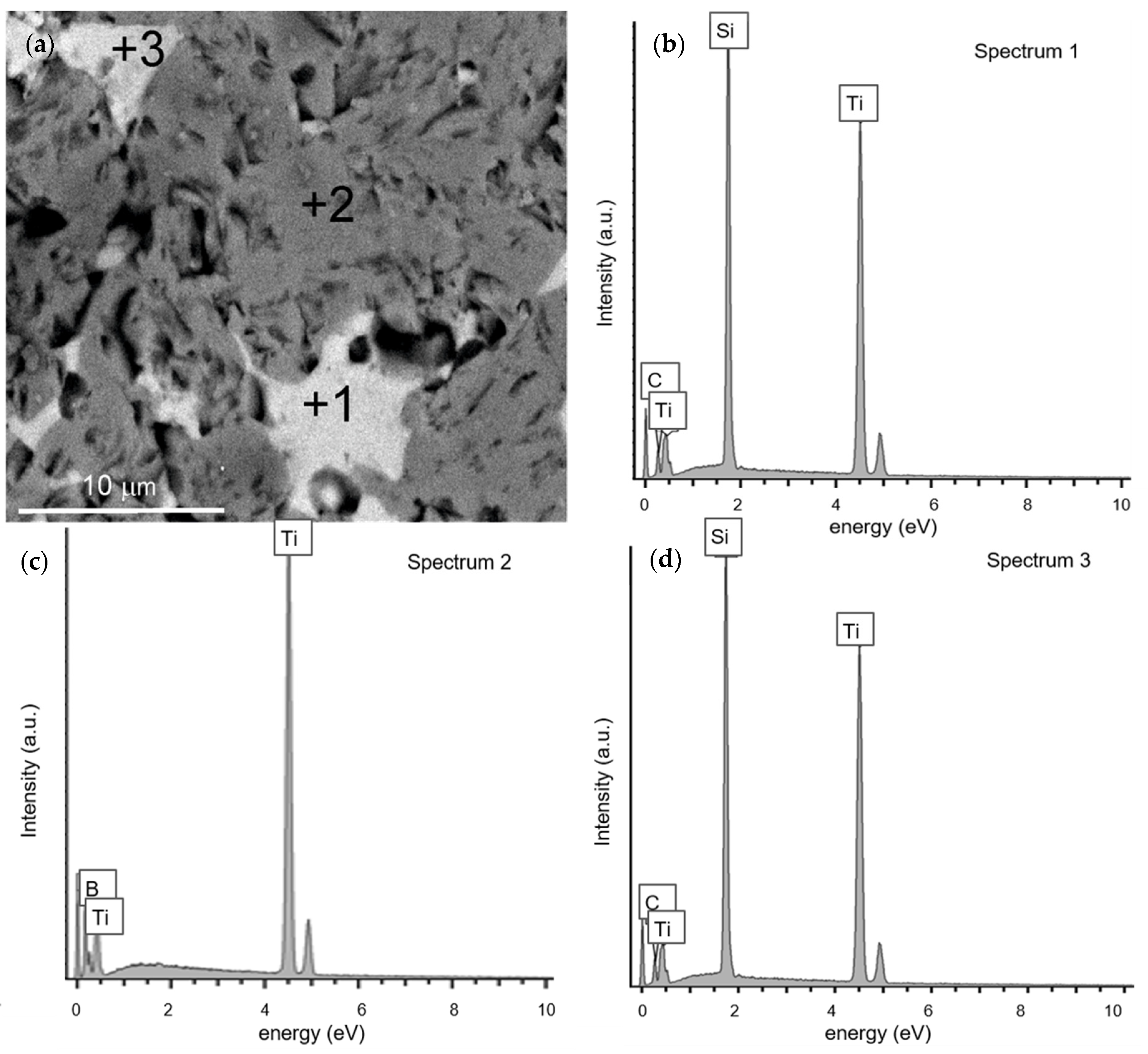
3.3. Microstructure
3.4. Hardness and Friction–Wear Properties
4. Conclusions
- Spark plasma sintering is an effective and fast method for the densification of TiB2/Ti5Si3 powders. The addition of 10–20 wt % of Ti5Si3 is beneficial for the density of TiB2/Ti5Si3 composites. The relative density of the produced composites is up to 98.4% of the theoretical composites.
- SPS sintering of the TiB2/Ti5Si3 initial powders at 1600 °C and 1700 °C results in the formation of TiC due to the effect of carbon diffusion from the graphite components of the sintering die.
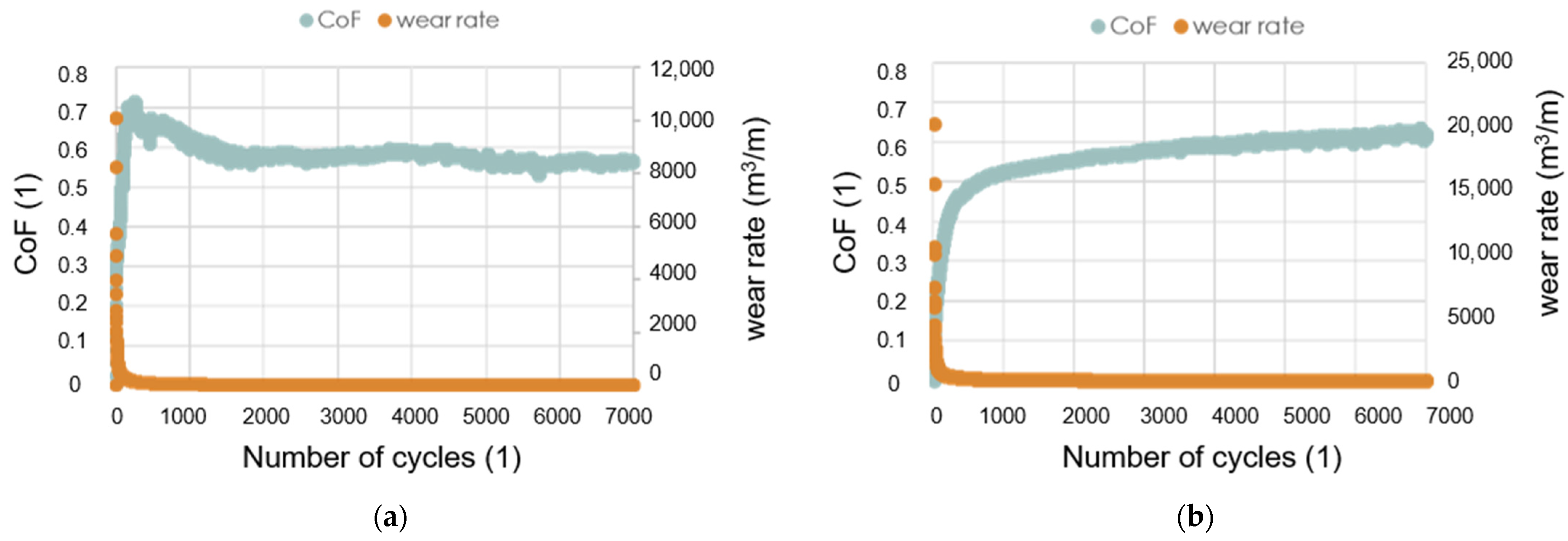
- The hardness of the produced composites decreases with Ti5Si3 content, but their resistance to wear in friction contact with WC increases with it, and for composites containing 20% of this additive, it increases by almost 30%.
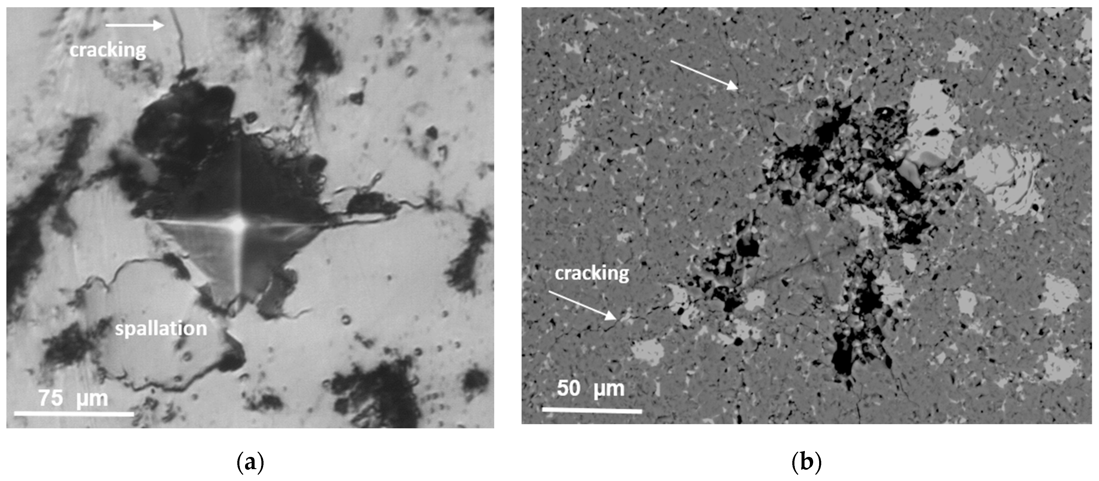
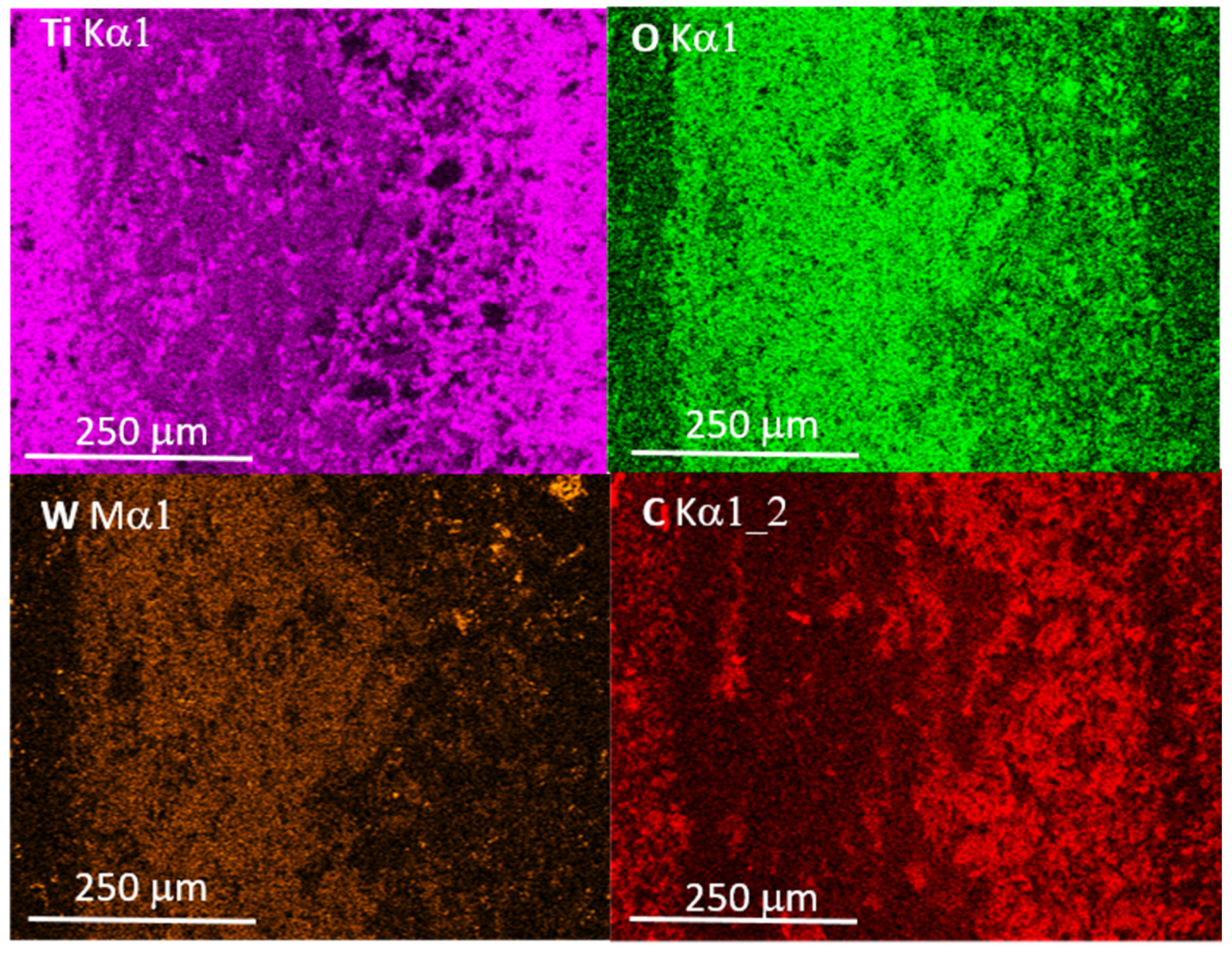
- The main mechanism of wear is abrasion. The presence of titanium, tungsten and boron oxides at worn areas indicate the tribo-oxidation reactions of these elements.
- The COF values of TiB2/Ti5Si3 composites in friction contact with WC were in the range of 0.54–0.61, similar to the value of the TiB2 sinter.
Author Contributions
Funding
Institutional Review Board Statement
Informed Consent Statement
Data Availability Statement
Acknowledgments
Conflicts of Interest
References
- Munro, R.G. Material Properties of Titanium Diboride. J. Res. Natl. Inst. Stand. Technol. 2000, 105, 709–720. [Google Scholar] [CrossRef] [PubMed]
- Basu, B.; Raju, G.B.; Suri, A.K. Processing and properties of monolithic TiB2based materials. Int. Mater. Rev. 2006, 51, 352–374. [Google Scholar] [CrossRef]
- Twardowska, A.; Morgiel, J.; Rajchel, B. Thermally Induced Crystallization of TiBx Thin Film after Deposition by Dual Beam IBAD Method. Mater. Today Proc. 2016, 3, 2646–2651. [Google Scholar] [CrossRef]
- Balcı, Ö.; Burkhardt, U.; Schmidt, M.; Hennicke, J.; Yagci, M.B.; Somer, M. Densification, microstructure and properties of TiB2 ceramics fabricated by spark plasma sintering. Mater. Charact. 2018, 145, 435–443. [Google Scholar] [CrossRef]
- Park, J.-H.; Koh, Y.-H.; Kim, H.-E.; Hwang, C.S.; Kang, E.S. Densification and Mechanical Properties of Titanium Diboride with Silicon Nitride as a Sintering Aid. J. Am. Ceram. Soc. 2004, 82, 3037–3042. [Google Scholar] [CrossRef]
- Vallauri, D.; Adrian, I.A.; Chrysanthou, A. TiC–TiB2 composites: A review of phase relationships, processing and properties. J. Eur. Ceram. Soc. 2008, 28, 1697–1713. [Google Scholar] [CrossRef]
- Murthy, T.S.R.C.; Basu, B.; Balasubramaniam, R.; Suri, A.K.; Subramanian, C.; Fotedar, R.K. Processing and Properties of TiB2 with MoSi2 Sinter-additive: A First Report. J. Am. Ceram. Soc. 2005, 89, 131–138. [Google Scholar] [CrossRef]
- Murthy, T.S.R.C.; Subramanian, C.; Fotedar, R.; Gonal, M.; Sengupta, P.; Kumar, S.; Suri, A. Preparation and property evaluation of TiB2+TiSi2 composite. Int. J. Refract. Met. Hard Mater. 2009, 27, 629–636. [Google Scholar] [CrossRef]
- Raju, G.B.; Basu, B. Densification, sintering reactions, and properties of titanium diboride with titanium disilicide as a sintering aid. J. Am. Ceram. Soc. 2007, 90, 3415–3423. [Google Scholar] [CrossRef]
- Mitra, R. Mechanical behavior and oxidation resistance of structural silicides. Int. Mater. Rev. 2006, 51, 13–64. [Google Scholar] [CrossRef]
- ASTM G99-17. Standard Test Method for Wear Testing with a Pin-on-Disk Apparatus; ASTM International: West Conshohocken, PA, USA, 2017. [Google Scholar]
- Demirskyi, D.; Sakka, Y. High-temperature reaction consolidation of TaC–TiB2 ceramic composites by spark-plasma sintering. J. Eur. Ceram. Soc. 2015, 35, 405–410. [Google Scholar] [CrossRef]
- Wdowik, U.D.; Wasik, M.; Twardowska, A. Influence of carbon dopants on the structure, elasticity and lattice dynamics of Ti5Si3CxNowotny phases. Model. Simul. Mater. Sci. Eng. 2016, 24, 025001. [Google Scholar] [CrossRef]
- Jain, D.; Reddy, K.M.; Mukhopadhyay, A.; Basu, B. Achieving uniform microstructure and superior mechanical properties in ultrafine grained TiB2–TiSi2 composites using innovative multi stage spark plasma sintering. Mater. Sci. Eng. A 2010, 528, 200–207. [Google Scholar] [CrossRef]
- Mukhopadhyay, A.; Raju, G.; Basu, B.; Suri, A. Correlation between phase evolution, mechanical properties and instrumented indentation response of TiB2-based ceramics. J. Eur. Ceram. Soc. 2009, 29, 505–516. [Google Scholar] [CrossRef]
- Rosenkranz, R.; Frommeyer, G.; Smarsly, W. Microstructures and properties of high melting point intermetallic Ti5Si3 and TiSi2 compounds. Mater. Sci. Eng. A 1992, 152, 288–294. [Google Scholar] [CrossRef]
- Sulima, I.; Figiel, P.; Suśniak, M.; Świątek, M. Sintering of TiB2 ceramics. Arch. Mater. Sci. Eng. 2007, 28, 687–690. [Google Scholar]
- Scharf, T.W.; Rajendran, A.; Banerjee, R.; Sequeda, F. Growth, structure and friction behavior of titanium doped tungsten disulphide (Ti-WS2) nanocomposite thin films. Thin Solid Film. 2009, 517, 5666–5675. [Google Scholar] [CrossRef]
- Woydt, M. Tribological characteristics of polycrystalline Magnéli-type titanium dioxides. Tribol. Lett. 2000, 8, 117–130. [Google Scholar] [CrossRef]


| Powder Mixture Composition | SPS Conditions Temperature/Time | Phase Compositionafter Sintering | ρ Theoretical (%) | Hardness |
|---|---|---|---|---|
| TiB2/10 wt % Ti5Si3 | 1600 °C/35 MPa/10 min | TiB2/7 wt % Ti5Si3/3 wt % TiC | 94.8 | 1961 ± 15 HV1 |
| TiB2/10 wt % Ti5Si3 | 1700 °C/35 MPa/10 min | TiB2/8 wt % Ti5Si3/4 wt % TiC | 96.5 | 2180 ± 28 HV1 |
| TiB2/20 wt % Ti5Si3 | 1600 °C/35 MPa/10 min | TiB2/16 wt % Ti5Si3/2 wt % TiC | 96.9 | 1864 ± 40 HV1 |
| TiB2/20 wt % Ti5Si3 | 1700 °C/35 MPa/10 min | TiB2/16 wt % Ti5Si3/2 wt % TiC | 98.2 | 1953 ± 34 HV1 |
| TiB2 | 1700 °C/35 MPa/10 min | TiB2 | 78.6 | 2400 ± 45 HV1 |
Publisher’s Note: MDPI stays neutral with regard to jurisdictional claims in published maps and institutional affiliations. |
© 2021 by the authors. Licensee MDPI, Basel, Switzerland. This article is an open access article distributed under the terms and conditions of the Creative Commons Attribution (CC BY) license (https://creativecommons.org/licenses/by/4.0/).
Share and Cite
Twardowska, A.; Podsiadło, M.; Sulima, I.; Bryła, K.; Hyjek, P. Microstructure and Properties of TiB2 Composites Produced by Spark Plasma Sintering with the Addition of Ti5Si3. Materials 2021, 14, 3812. https://doi.org/10.3390/ma14143812
Twardowska A, Podsiadło M, Sulima I, Bryła K, Hyjek P. Microstructure and Properties of TiB2 Composites Produced by Spark Plasma Sintering with the Addition of Ti5Si3. Materials. 2021; 14(14):3812. https://doi.org/10.3390/ma14143812
Chicago/Turabian StyleTwardowska, Agnieszka, Marcin Podsiadło, Iwona Sulima, Krzysztof Bryła, and Paweł Hyjek. 2021. "Microstructure and Properties of TiB2 Composites Produced by Spark Plasma Sintering with the Addition of Ti5Si3" Materials 14, no. 14: 3812. https://doi.org/10.3390/ma14143812
APA StyleTwardowska, A., Podsiadło, M., Sulima, I., Bryła, K., & Hyjek, P. (2021). Microstructure and Properties of TiB2 Composites Produced by Spark Plasma Sintering with the Addition of Ti5Si3. Materials, 14(14), 3812. https://doi.org/10.3390/ma14143812