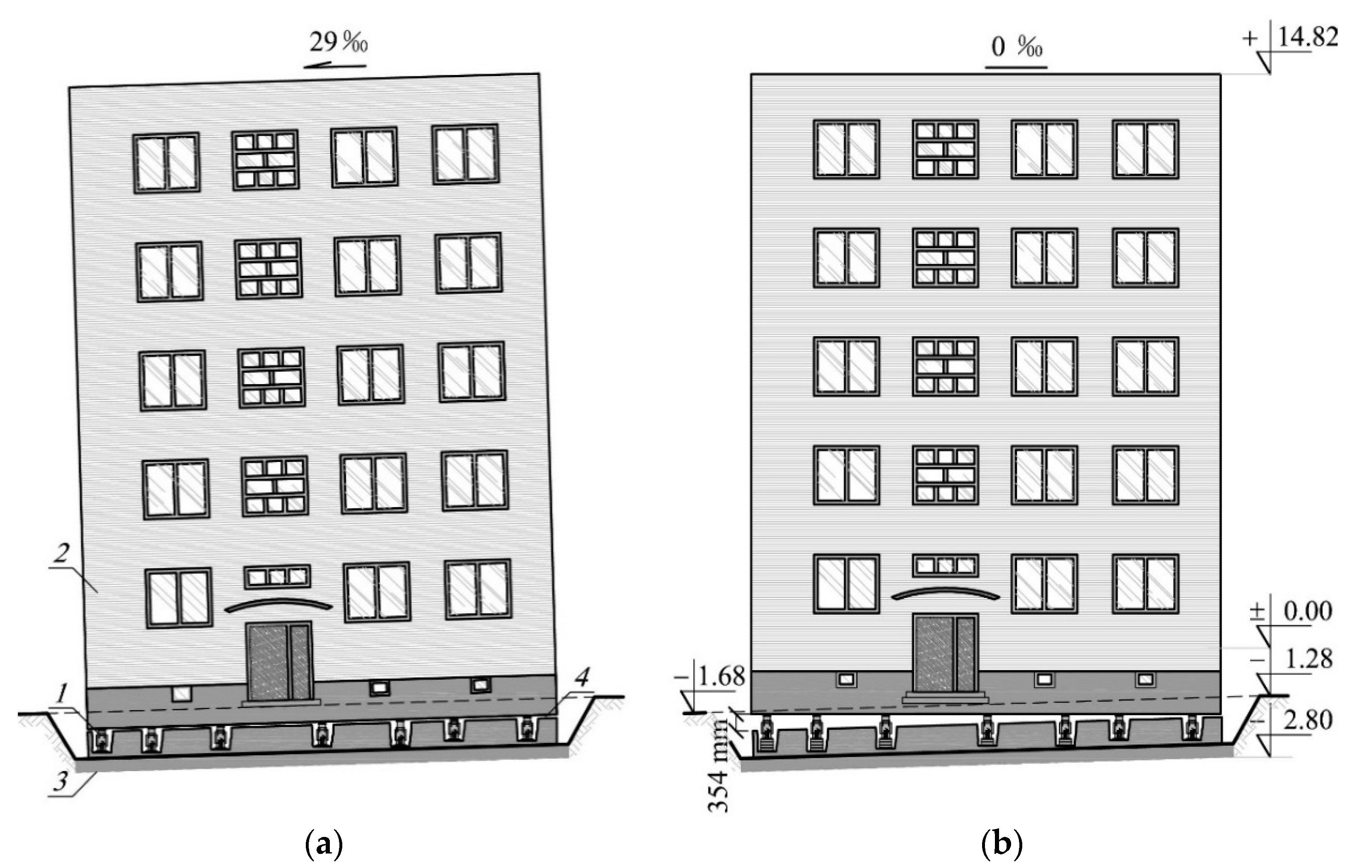
Figure 1.
Façade of the building the tilt of which was removed: (a) jacks installed in the building walls, (b) the building after uneven lifting; 1—temporary support, 2—unevenly lifted part of the building, 3—part of the building remaining in the ground, 4—detachment plane of the building.
Figure 1.
Façade of the building the tilt of which was removed: (a) jacks installed in the building walls, (b) the building after uneven lifting; 1—temporary support, 2—unevenly lifted part of the building, 3—part of the building remaining in the ground, 4—detachment plane of the building.
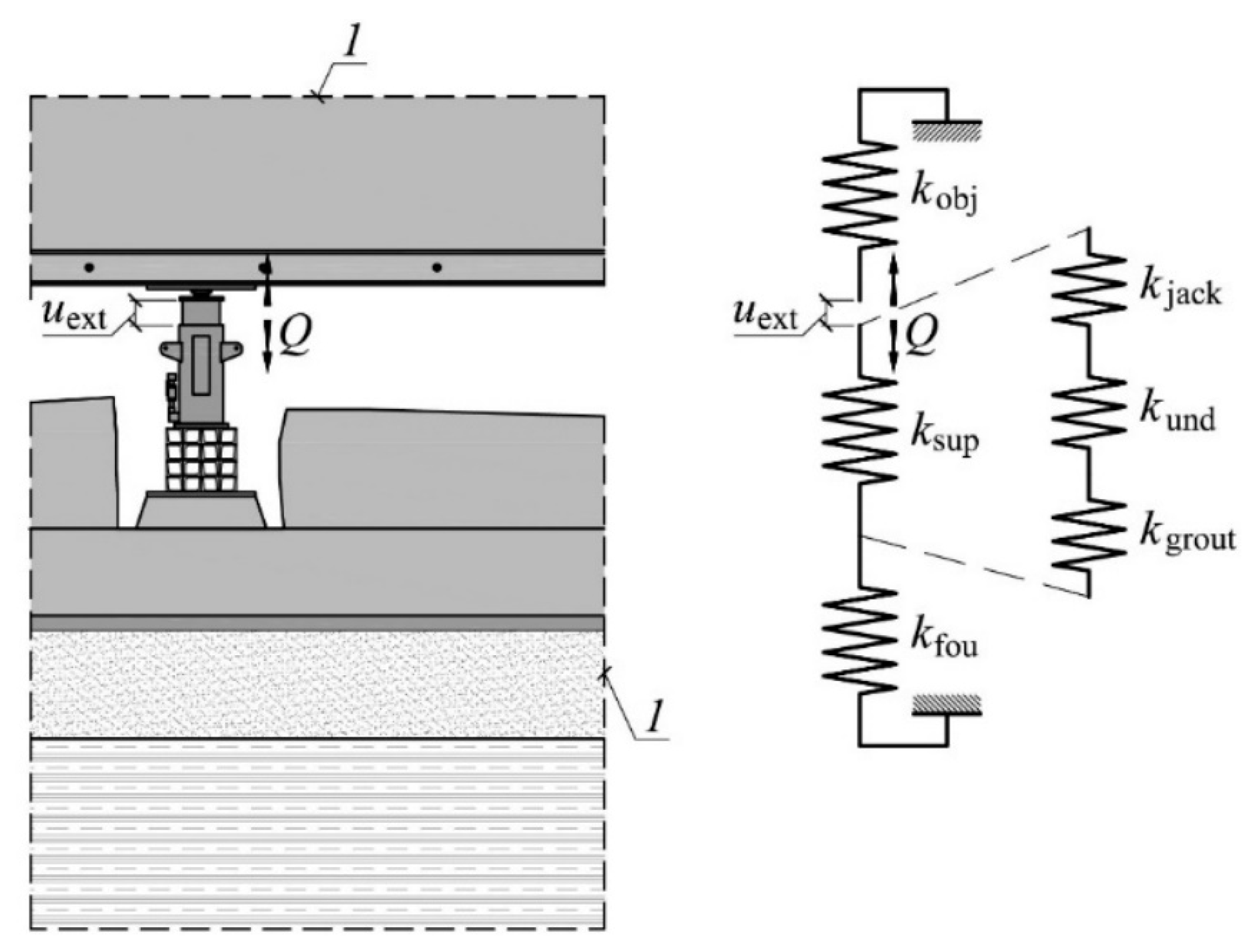
Figure 2.
Change in the length of the active support and displacements of building elements in the place of its installation: 1—active support, 2—passive support, 3—unevenly lifted part of the building, 4—part of the building remaining in the ground, 5—original position of the part of the building, uext—forced extension of the active support piston, uobj—displacement of the lifted part of the building, ufou—displacement of the unlifted part, Δlsup—change in the length of the support, ΔQ—change in the value of force in the support.
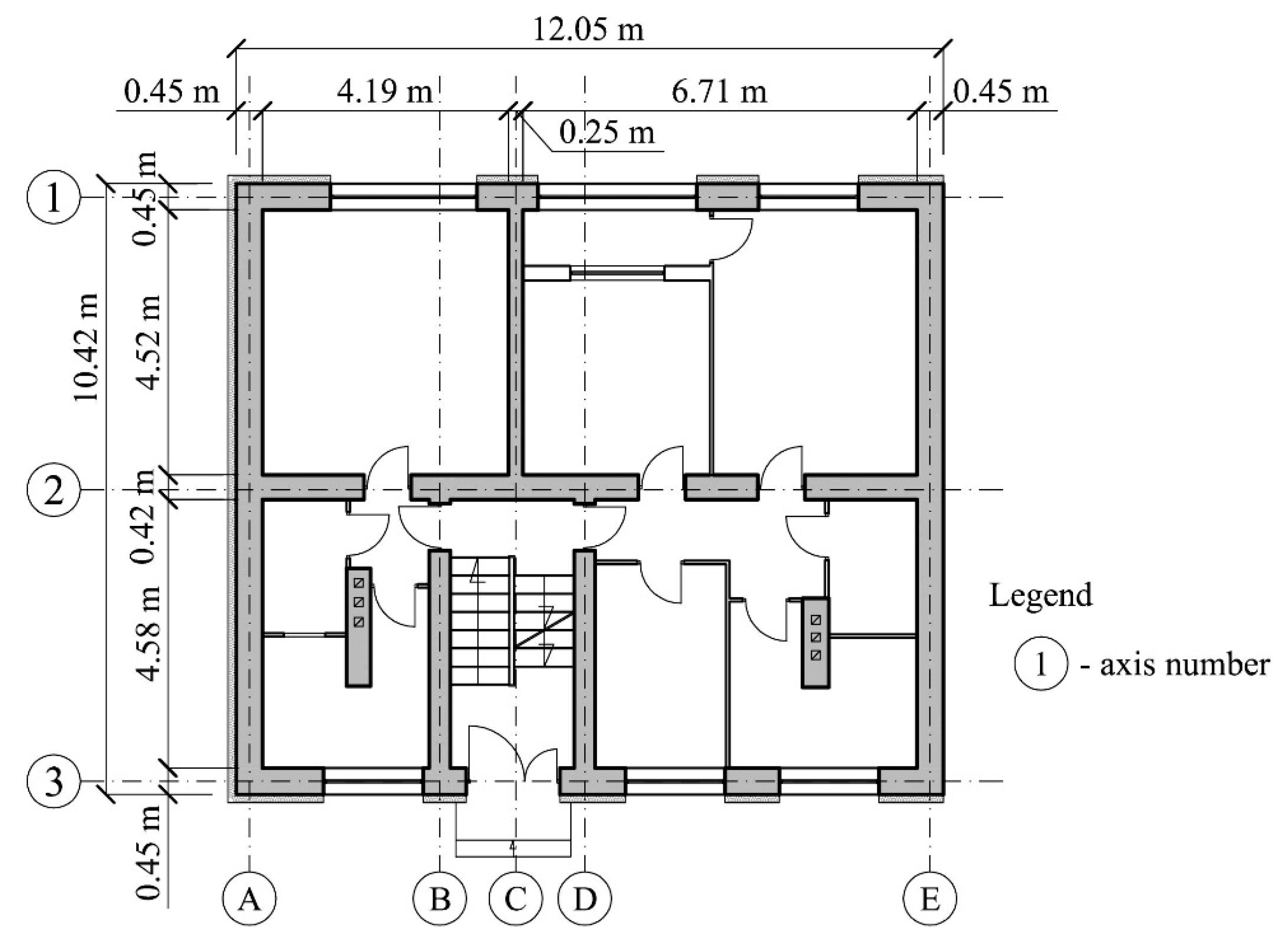
Figure 3.
Ground floor plan.
Figure 3.
Ground floor plan.
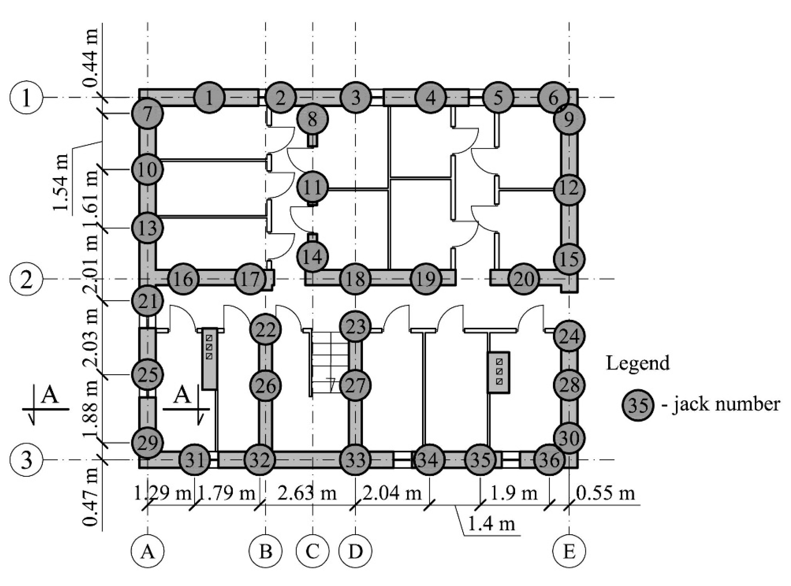
Figure 4.
Arrangement of jacks installed in the cellar walls (section A—A is shown in
Figure 5).
Figure 4.
Arrangement of jacks installed in the cellar walls (section A—A is shown in
Figure 5).
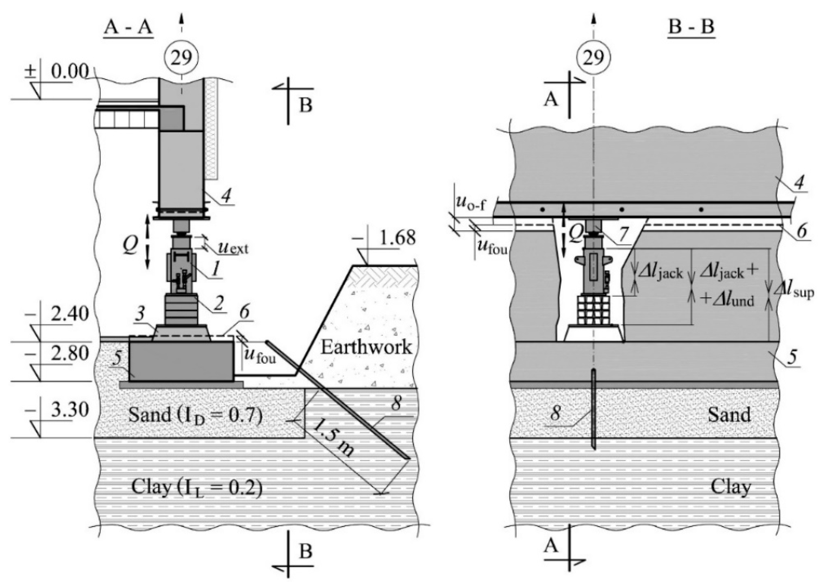
Figure 5.
The following measurements were carried out: the forced jack piston extension (uext), displacement of building elements (uo-f, ufou), changes in support length (Δlsup), changes in length of support elements (Δljack + Δlund, Δljack) and force in the support (Q): 1—jack, 2—stack of parallelepiped elements, 3—concrete grout, 4—elevated part of the building, 5—part of the building remaining in the ground, 6—original position of the part of the building, 7—dynamometer, 8—steel rod driven into the ground.
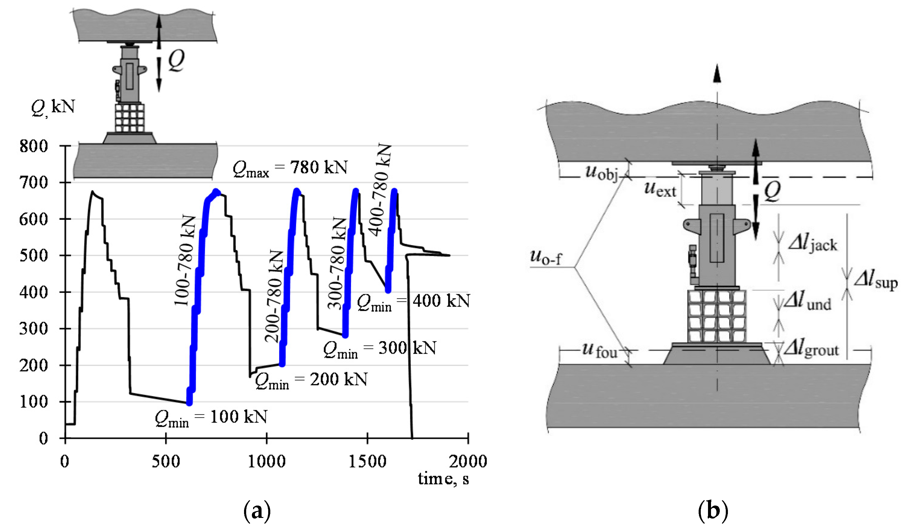
Figure 6.
Test program: (a) cycles of the change of the value Q of the force in support no. 29 (phases of the monotonic load increase being the subject of analysis are in bold), (b) symbols of movements of the building parts and changes in the length of support elements.
Figure 6.
Test program: (a) cycles of the change of the value Q of the force in support no. 29 (phases of the monotonic load increase being the subject of analysis are in bold), (b) symbols of movements of the building parts and changes in the length of support elements.
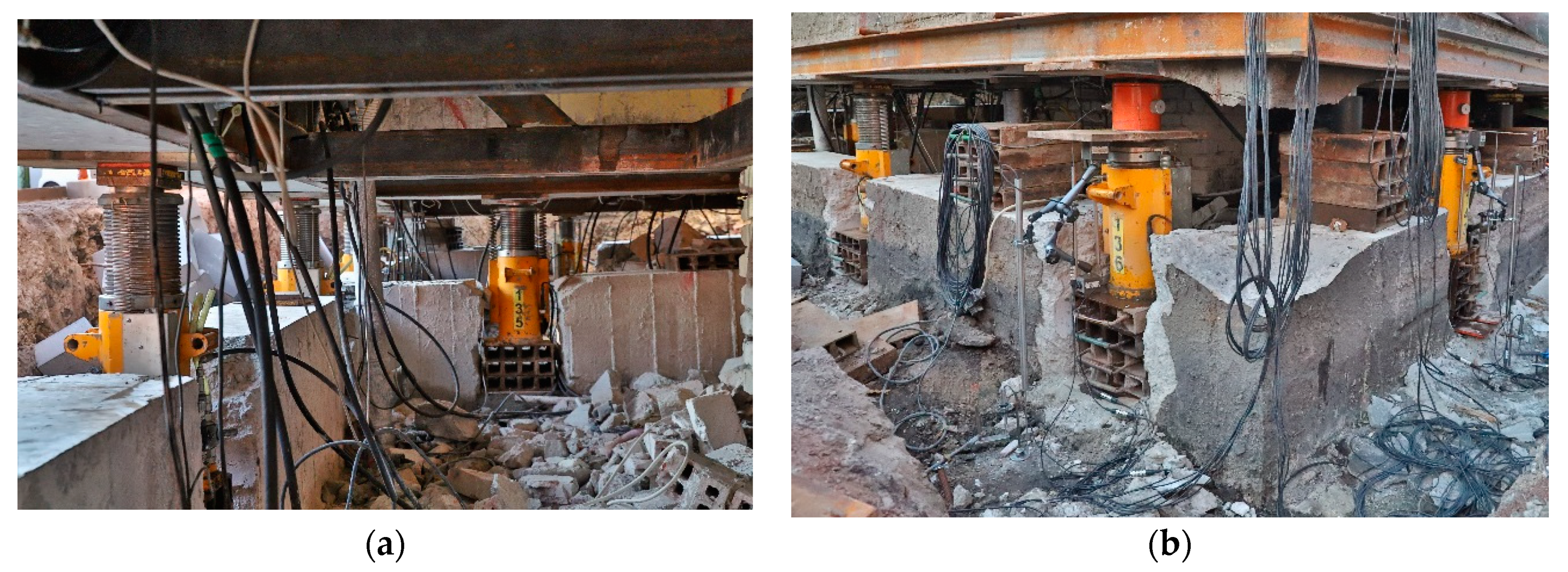
Figure 7.
Building during measurements: (a) unevenly lifted part resting on the jacks, (b) support no. 29 during measurements.
Figure 7.
Building during measurements: (a) unevenly lifted part resting on the jacks, (b) support no. 29 during measurements.
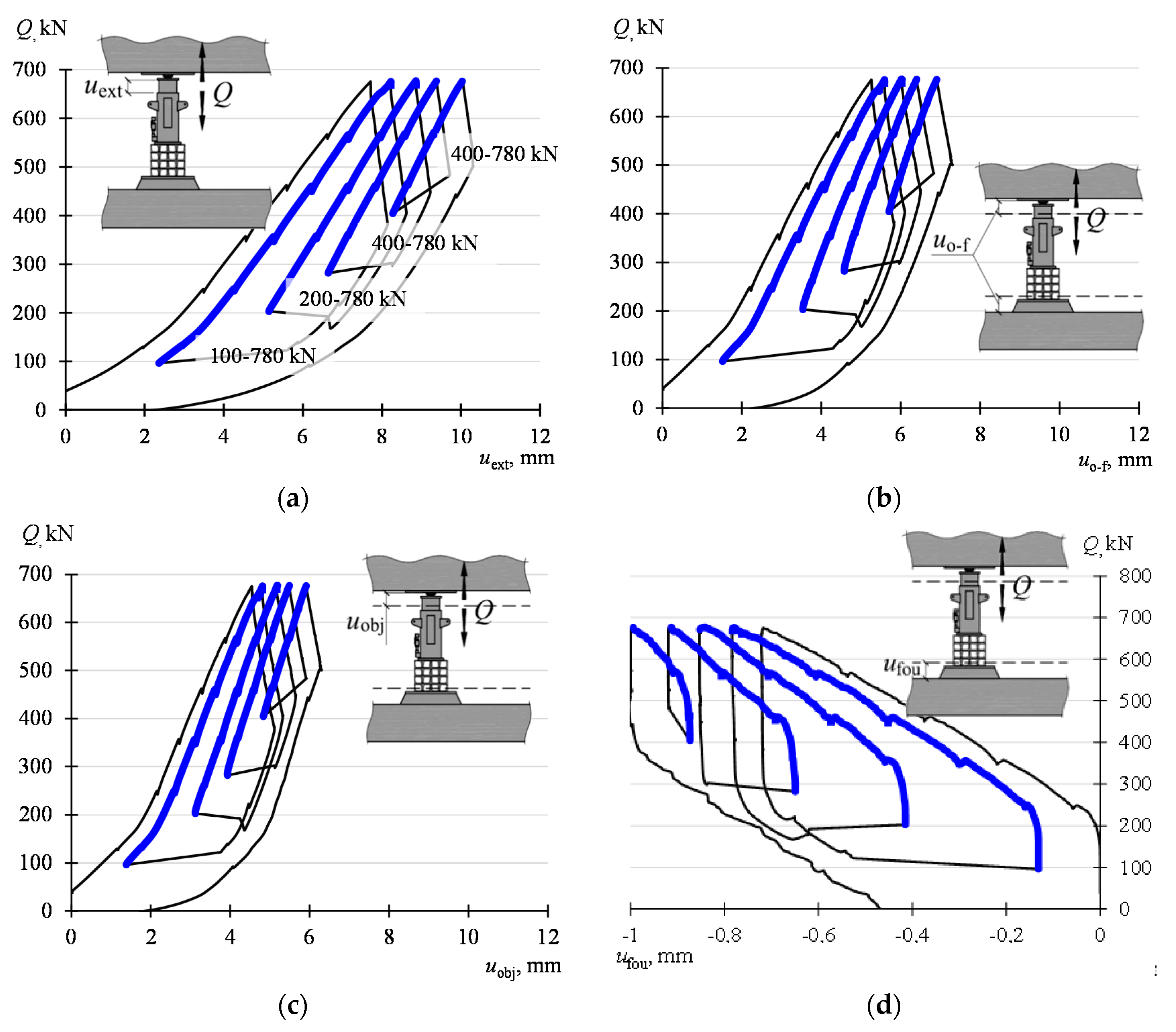
Figure 8.
Force—extension and force—displacement dependencies of the building structure elements: (a) Q−uext, (b) Q−uo-f, (c) Q−uobj, (d) Q−ufou.
Figure 8.
Force—extension and force—displacement dependencies of the building structure elements: (a) Q−uext, (b) Q−uo-f, (c) Q−uobj, (d) Q−ufou.
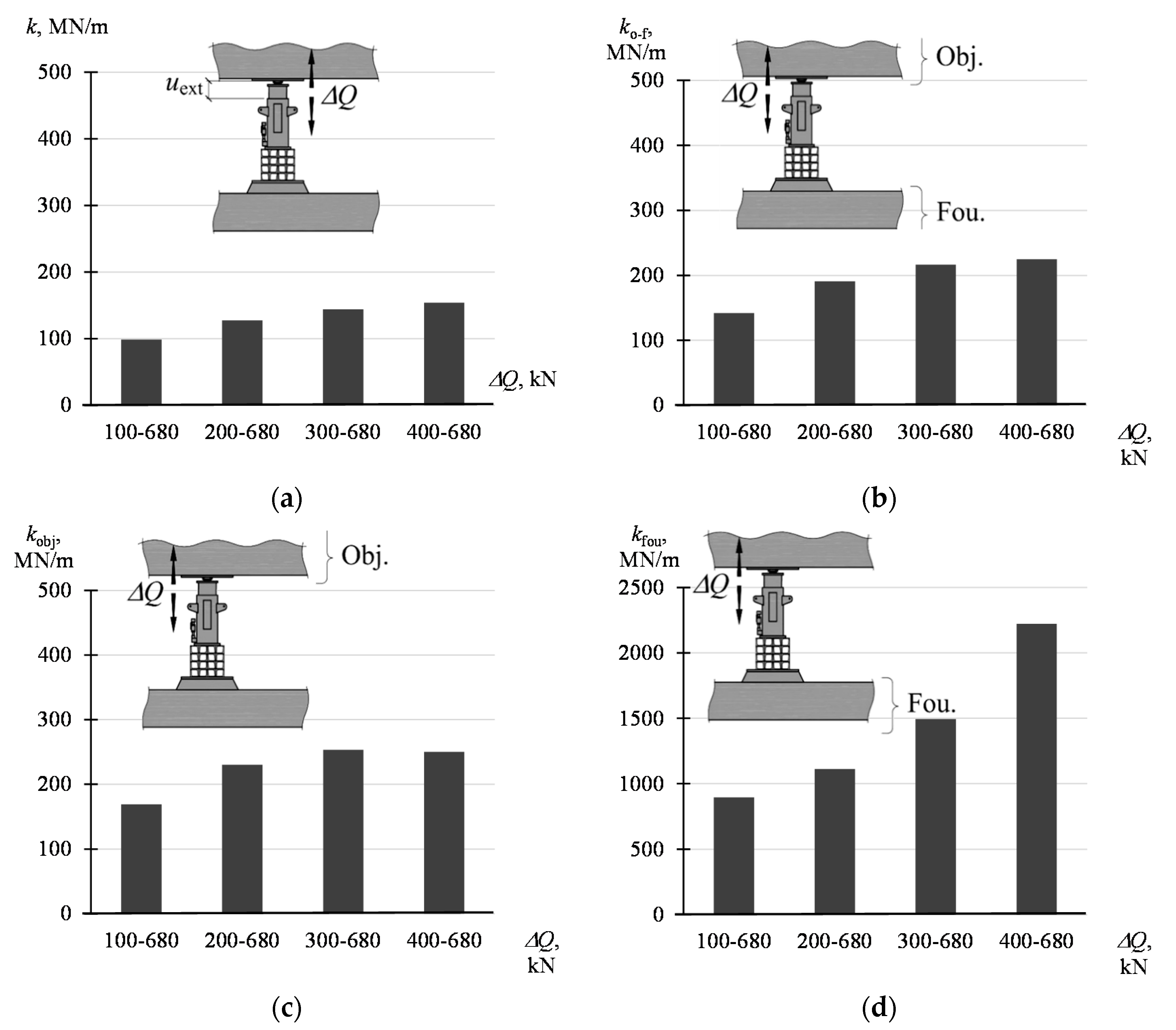
Figure 9.
Stiffness of the system and its elements corresponding to the change ΔQ in the range of Qmin–Qmax: (a) k acc. to (4), (b) ko-f acc. to (7), (c) kobj acc. to (5), (d) kfou acc. to (6).
Figure 9.
Stiffness of the system and its elements corresponding to the change ΔQ in the range of Qmin–Qmax: (a) k acc. to (4), (b) ko-f acc. to (7), (c) kobj acc. to (5), (d) kfou acc. to (6).
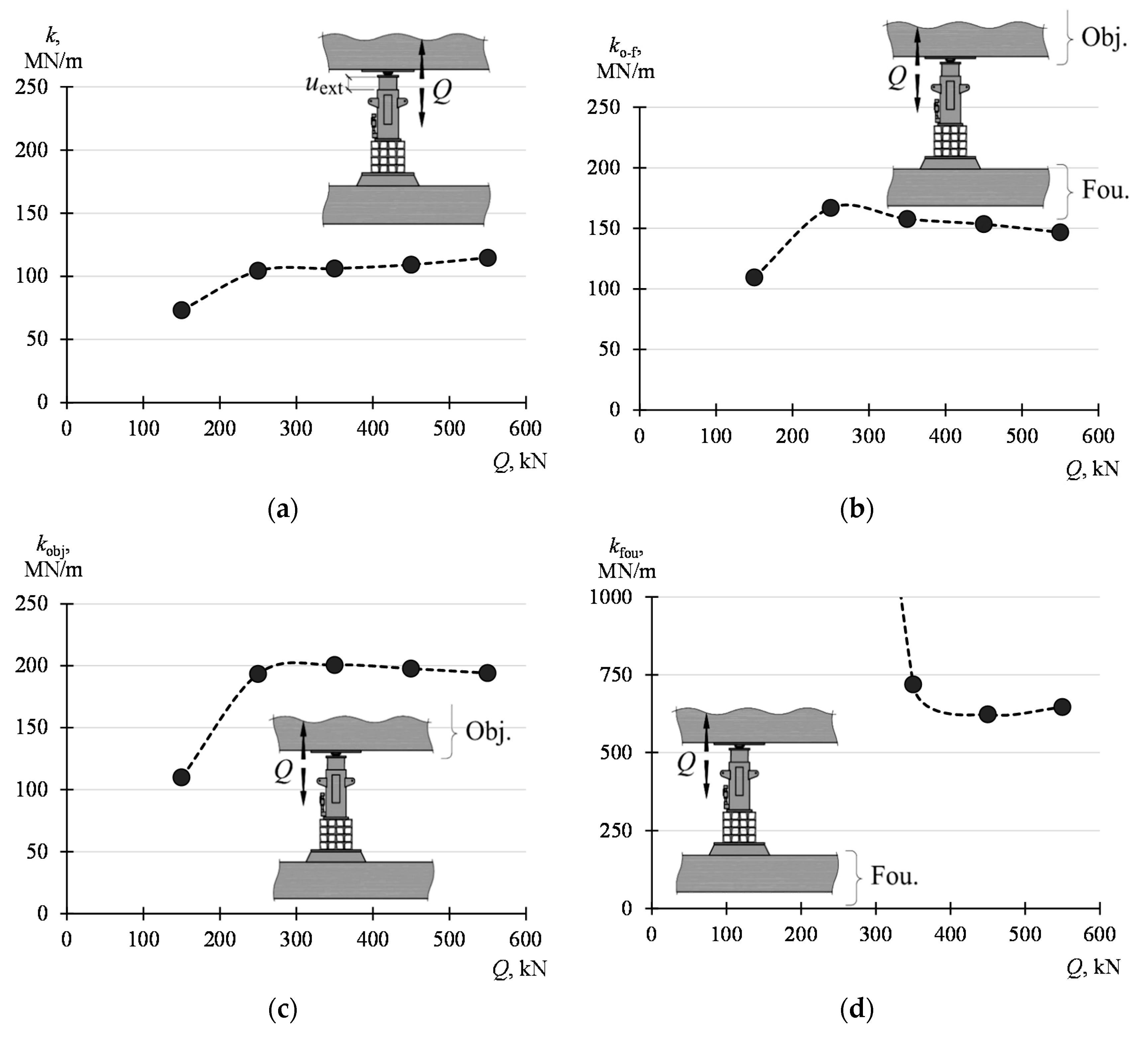
Figure 10.
Influence of the value Q on the stiffnesses of the system and elements of the system: (a) k, (b) ko-f, (c) kobj, (d) kfou.
Figure 10.
Influence of the value Q on the stiffnesses of the system and elements of the system: (a) k, (b) ko-f, (c) kobj, (d) kfou.
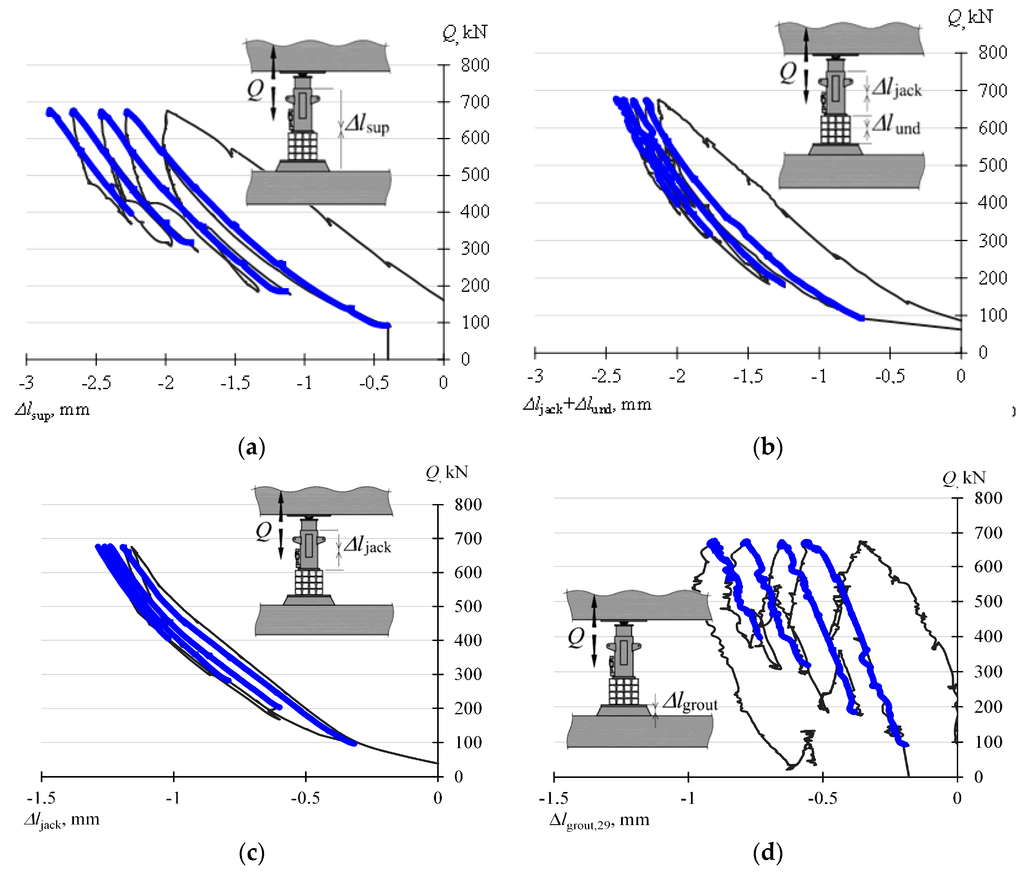
Figure 11.
Changes in the length of the temporary support and its elements: (a) Δlsup, (b) Δljack + Δlund, (c) Δljack, (d) Δlgrout.
Figure 11.
Changes in the length of the temporary support and its elements: (a) Δlsup, (b) Δljack + Δlund, (c) Δljack, (d) Δlgrout.
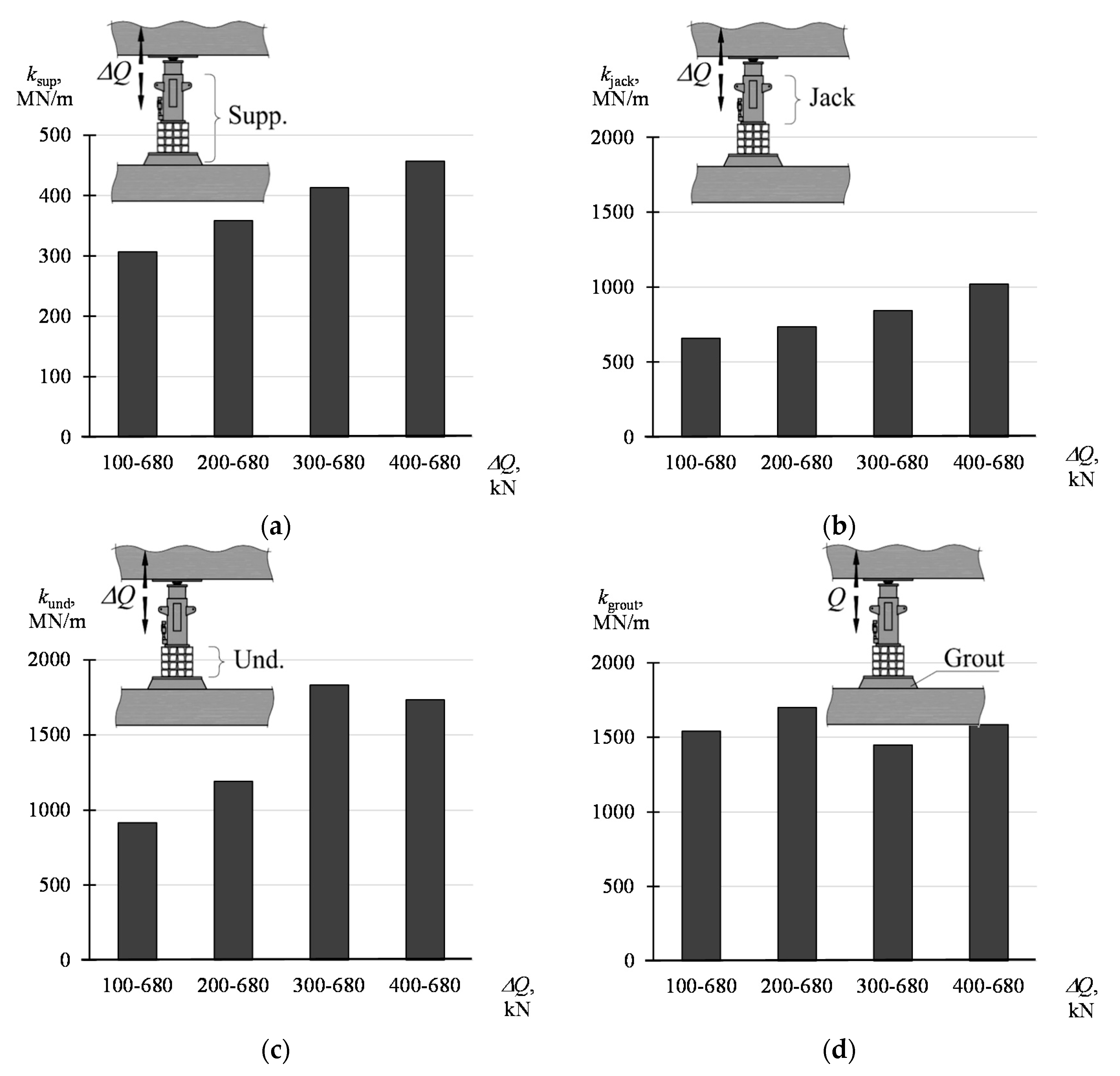
Figure 12.
Stiffness of the support and its elements corresponding to the change ΔQ in the range of Qmin–Qmax: (a) ksup, (b) kjack, (c) kund, (d) kgrout.
Figure 12.
Stiffness of the support and its elements corresponding to the change ΔQ in the range of Qmin–Qmax: (a) ksup, (b) kjack, (c) kund, (d) kgrout.
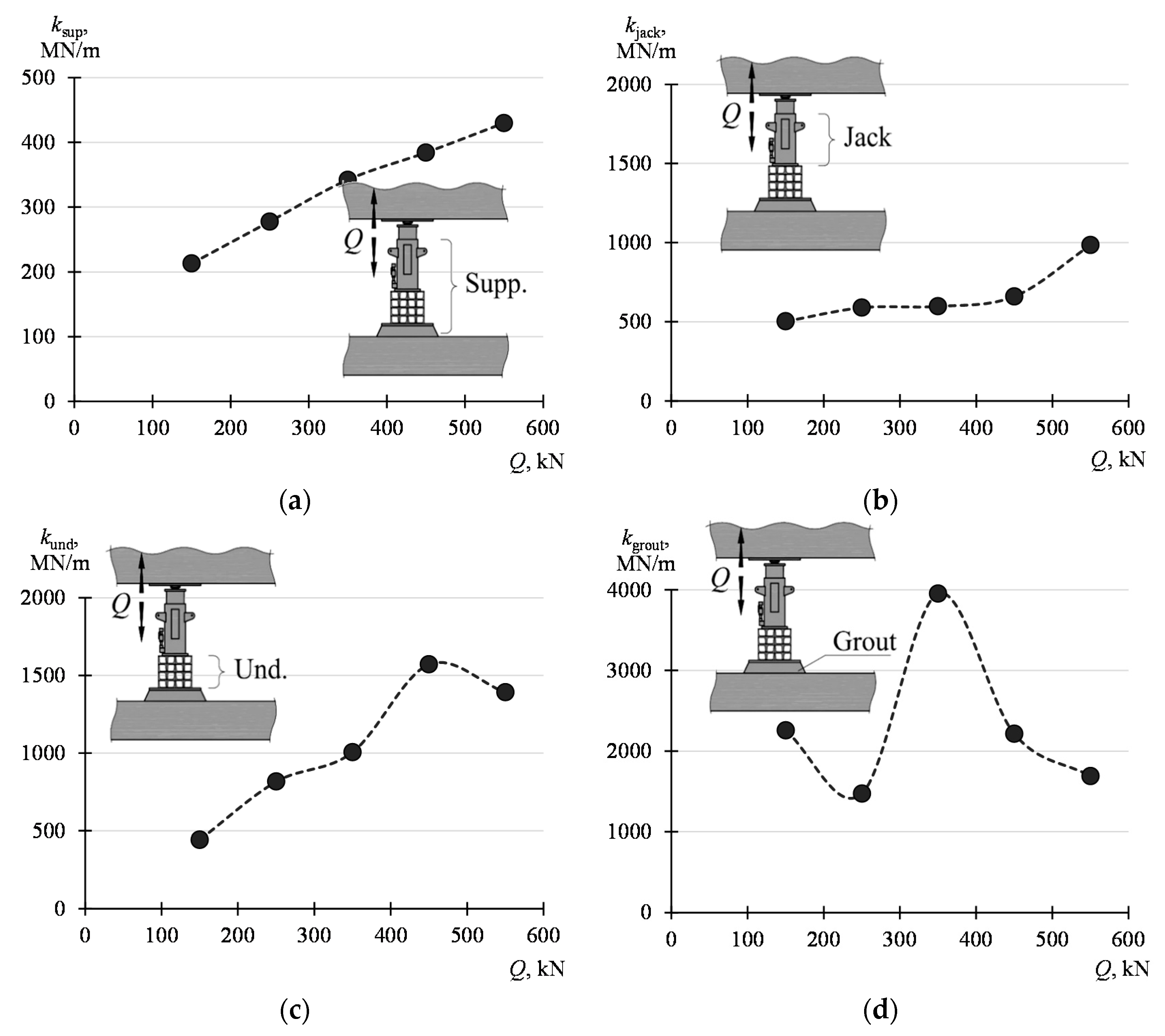
Figure 13.
Influence of the value Q on the stiffnesses of the support and elements of the support: (a) ksup, (b) kjack, (c) kund, (d) kgrout.
Figure 13.
Influence of the value Q on the stiffnesses of the support and elements of the support: (a) ksup, (b) kjack, (c) kund, (d) kgrout.
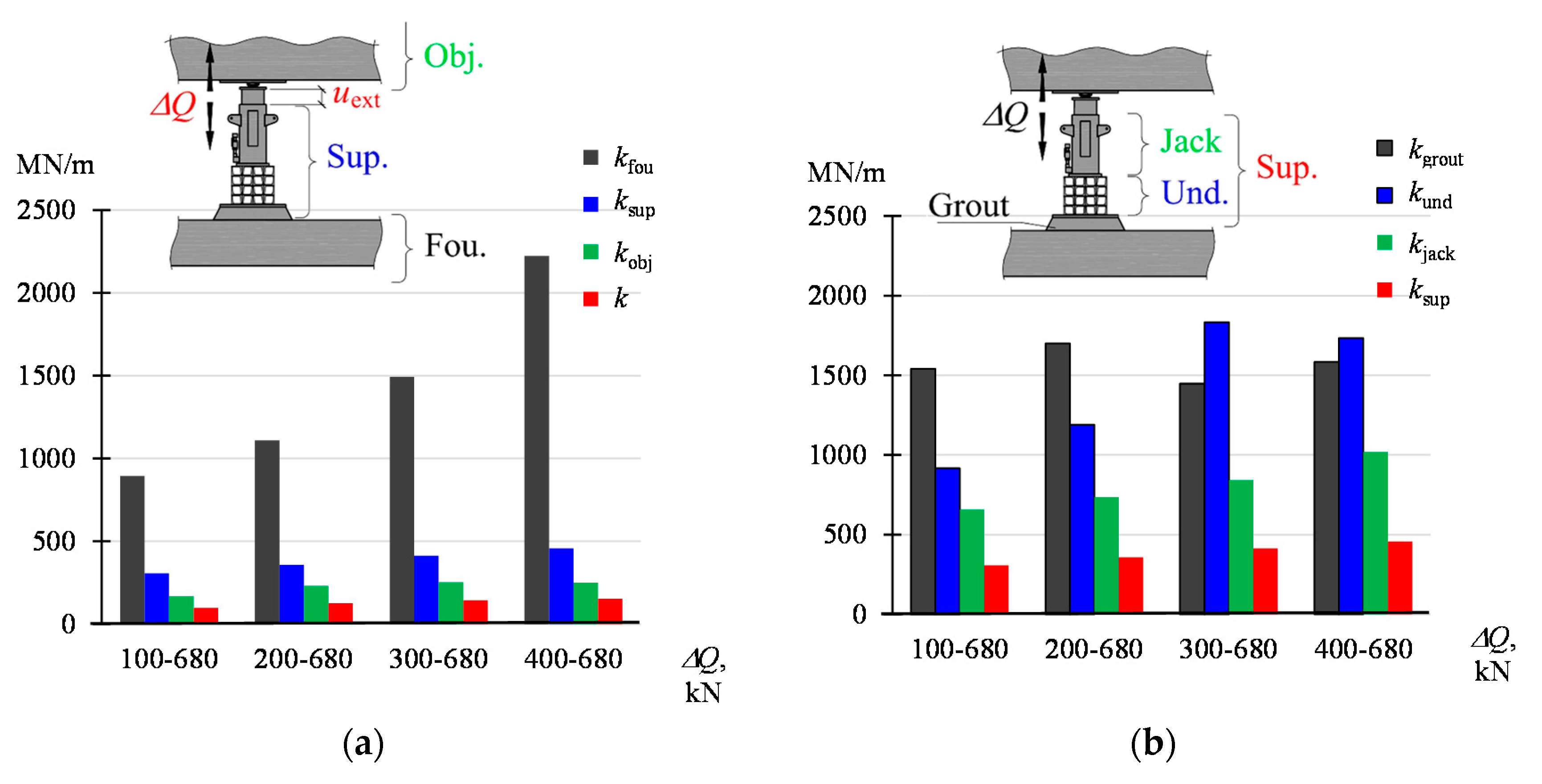
Figure 14.
Stiffnesses corresponding to the change ΔQ in the range of Qmin–Qmax: (a) kfou, ksup, kobj, k, (b) kgrout, kund, kjack, ksup.
Figure 14.
Stiffnesses corresponding to the change ΔQ in the range of Qmin–Qmax: (a) kfou, ksup, kobj, k, (b) kgrout, kund, kjack, ksup.
Figure 15.
The stiffness k of the system determined based on (4), (10) and (11).
Figure 15.
The stiffness k of the system determined based on (4), (10) and (11).
Figure 16.
Dependencies between the analyzed stiffnesses; 1—boundary conditions.
Figure 16.
Dependencies between the analyzed stiffnesses; 1—boundary conditions.
Figure 17.
Analysis of the influence of stiffness of the components on the stiffness
k of the system (the grey line indicates the respective values from
Figure 15): (
a)
kund, (
b)
kgrout, (
c)
kfou, (
d)
kobj.
Figure 17.
Analysis of the influence of stiffness of the components on the stiffness
k of the system (the grey line indicates the respective values from
Figure 15): (
a)
kund, (
b)
kgrout, (
c)
kfou, (
d)
kobj.
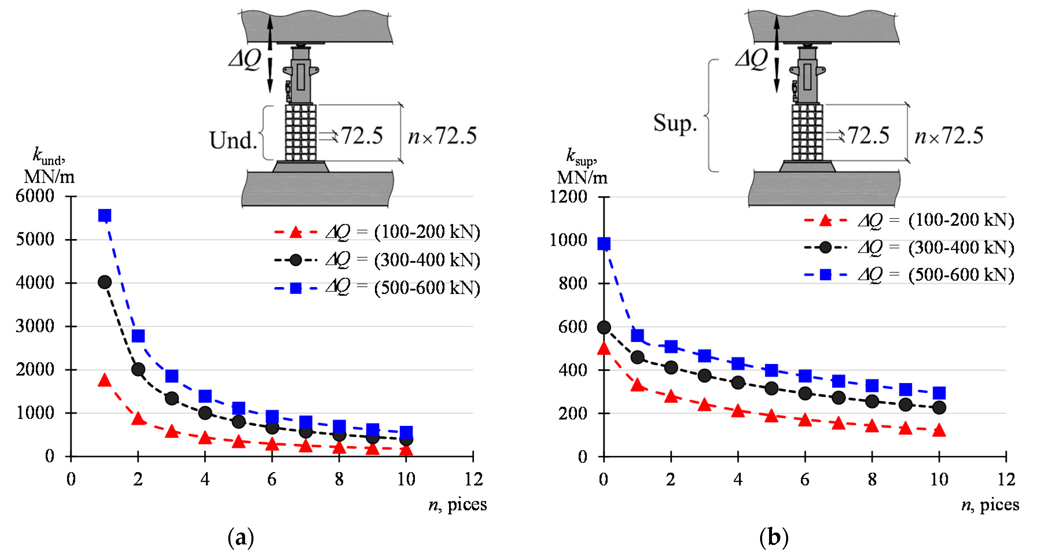
Figure 18.
Influence of the number n of the parallelepiped elements on the stiffness of: (a) underlay, (b) support.
Figure 18.
Influence of the number n of the parallelepiped elements on the stiffness of: (a) underlay, (b) support.
Table 1.
The values of extension, displacements and stiffness of the system and its elements corresponding to the change ΔQ in the range of Qmin–Qmax.
Table 1.
The values of extension, displacements and stiffness of the system and its elements corresponding to the change ΔQ in the range of Qmin–Qmax.
| Qmin–Qmax | uext | uo-f | uobj | ufou | k | ko-f | kobj | kfou |
|---|
| kN | mm | MN/m |
|---|
| 100–780 | 6.073 | 4.223 | 3.552 | 0.670 | 99 | 142 | 169 | 895 |
| 200–780 | 4.708 | 3.147 | 2.607 | 0.540 | 127 | 191 | 230 | 1111 |
| 300–780 | 4.157 | 2.770 | 2.368 | 0.402 | 144 | 217 | 253 | 1493 |
| 400–780 | 3.897 | 2.668 | 2.398 | 0.270 | 154 | 225 | 250 | 2223 |
Table 2.
Displacements of the building parts and stiffnesses of the system and elements of the building.
Table 2.
Displacements of the building parts and stiffnesses of the system and elements of the building.
| Qmin–Qmax | uext | uo-f | uobj | ufou | k | ko-f | kobj | kfou |
|---|
| kN | mm | MN/m |
|---|
| 100–200 | 1.368 | 0.914 | 0.911 | 0.003 | 73 | 109 | 110 | 32452 |
| 200–300 | 0.958 | 0.599 | 0.517 | 0.027 | 104 | 167 | 193 | 3690 |
| 300–400 | 0.942 | 0.634 | 0.498 | 0.139 | 106 | 158 | 201 | 719 |
| 400–500 | 0.916 | 0.652 | 0.506 | 0.160 | 109 | 153 | 198 | 623 |
| 500–600 | 0.871 | 0.682 | 0.515 | 0.155 | 115 | 147 | 194 | 646 |
Table 3.
Changes in the length and stiffness of the support and its elements in the range of Qmin–Qmax.
Table 3.
Changes in the length and stiffness of the support and its elements in the range of Qmin–Qmax.
| Qmin–Qmax | Δlsup | Δljack + Δlund | Δljack | Δlund | Δlgrout | ksup | kjack-und | kjack | kund | kgrout |
|---|
| kN | mm | MN/m |
|---|
| 100–780 | 1.956 | 1.567 | 0.912 | 0.655 | 0.389 | 307 | 383 | 658 | 916 | 1541 |
| 200–780 | 1.395 | 1.101 | 0.681 | 0.420 | 0.294 | 358 | 454 | 734 | 1190 | 1700 |
| 300–780 | 0.969 | 0.692 | 0.474 | 0.218 | 0.276 | 413 | 578 | 844 | 1832 | 1448 |
| 400–780 | 0.657 | 0.467 | 0.294 | 0.173 | 0.189 | 457 | 642 | 1020 | 1734 | 1585 |
Table 4.
Changes in the length of the support and its elements corresponding to the change Q in the range of Qmin–Qmax.
Table 4.
Changes in the length of the support and its elements corresponding to the change Q in the range of Qmin–Qmax.
| Qmin–Qmax | Δlsup | Δljack+Δlund | Δljack | Δlund | Δlgrout | ksup | kjack_und | kjack | kund | kgrout |
|---|
| kN | mm | MN/m |
|---|
| 100–200 | 0.469 | 0.439 | 0.199 | 0.226 | 0.044 | 213 | 228 | 503 | 443 | 2258 |
| 200–300 | 0.360 | 0.310 | 0.170 | 0.122 | 0.068 | 278 | 323 | 590 | 816 | 1474 |
| 300–400 | 0.292 | 0.273 | 0.167 | 0.099 | 0.025 | 342 | 366 | 597 | 1006 | 3954 |
| 400–500 | 0.260 | 0.216 | 0.151 | 0.064 | 0.045 | 384 | 462 | 660 | 1571 | 2217 |
| 500–600 | 0.233 | 0.174 | 0.102 | 0.072 | 0.059 | 430 | 574 | 985 | 1391 | 1692 |
Table 5.
The stiffnesses of the system determined based on (4), (10) and (11).
Table 5.
The stiffnesses of the system determined based on (4), (10) and (11).
| Qmin–Qmax | k According to (4) | k According to (10) | k According to (11) |
|---|
| kN | MN/m | MN/m | MN/m |
|---|
| 100–200 | 73 | 72 | 72 |
| 200–300 | 104 | 111 | 104 |
| 300–400 | 106 | 108 | 108 |
| 400–500 | 109 | 108 | 110 |
| 500–600 | 115 | 111 | 109 |
Table 6.
Stack stiffness depending on the number n of the parallelepiped elements forming the stack for different intervals ΔQ.
Table 6.
Stack stiffness depending on the number n of the parallelepiped elements forming the stack for different intervals ΔQ.
| Qmin–Qmax | n = 1 | n = 2 | n = 3 | n = 4 | n = 5 | n = 6 | n = 7 | n = 8 | n = 9 | n = 10 |
|---|
| kN | MN/m |
|---|
| 100–200 | 1772 | 886 | 591 | 443 | 354 | 295 | 253 | 222 | 197 | 177 |
| 200–300 | 3264 | 1632 | 1088 | 816 | 653 | 544 | 466 | 408 | 363 | 326 |
| 300–400 | 4024 | 2012 | 1341 | 1006 | 805 | 671 | 575 | 503 | 447 | 402 |
| 400–500 | 6284 | 3142 | 2095 | 1571 | 1257 | 1047 | 898 | 786 | 698 | 628 |
| 500–600 | 5564 | 2782 | 1855 | 1391 | 1113 | 927 | 795 | 696 | 618 | 556 |
Table 7.
Support stiffness depending on the number n of the parallelepiped elements forming the stack for different intervals ΔQ.
Table 7.
Support stiffness depending on the number n of the parallelepiped elements forming the stack for different intervals ΔQ.
| Qmin–Qmax | n = 0 | n = 1 | n = 2 | n = 3 | n = 4 | n = 5 | n = 6 | n = 7 | n = 8 | n = 9 | n = 10 |
|---|
| kN | MN/m |
|---|
| 100–200 | 503 | 334 | 281 | 242 | 213 | 190 | 172 | 157 | 144 | 133 | 124 |
| 200–300 | 590 | 373 | 335 | 304 | 278 | 256 | 237 | 221 | 207 | 195 | 184 |
| 300–400 | 597 | 460 | 413 | 374 | 342 | 316 | 293 | 273 | 255 | 240 | 227 |
| 400–500 | 660 | 471 | 438 | 409 | 384 | 362 | 342 | 325 | 309 | 294 | 281 |
| 500–600 | 985 | 560 | 509 | 466 | 430 | 399 | 372 | 349 | 328 | 310 | 294 |


