Abstract
An aluminum (Al) matrix with various transition metal (TM) additions is an effective alloying approach for developing high-specific-strength materials for use at elevated temperatures. Conventional fabrication processes such as casting or fusion-related methods are not capable of producing Al–TM alloys in bulk form. Solid phase processing techniques, such as extrusion, have been shown to maintain the microstructure of Al–TM alloys. In this study, extrusions are fabricated from gas-atomized aluminum powders (≈100–400 µm) that contain 12.4 wt % TM additives and an Al-based matrix reinforced by various Al–Fe–Cr–Ti intermetallic compounds (IMCs). Two different extrusion techniques, conventional hot extrusion and friction extrusion, are compared using fabricating rods. During extrusion, the strengthening IMC phases were extensively refined as a result of severe plastic deformation. Furthermore, the quasicrystal approximant IMC phase (70.4 wt % Al, 20.4 wt % Fe, 8.7 wt % Cr, 0.6 wt % Ti) observed in the powder precursor is replaced by new IMC phases such as Al3.2Fe and Al45Cr7-type IMCs. The Al3Ti-type IMC phase is partially dissolved into the Al matrix during extrusion. The combination of linear and rotational shear in the friction extrusion process caused severe deformation in the powders, which allowed for a higher extrusion ratio, eliminated linear voids, and resulted in higher ductility while maintaining strength comparable to that resulting from hot extrusion. Results from equilibrium thermodynamic calculations show that the strengthening IMC phases are stable at elevated temperatures (up to ≈ 600 °C), thus enhancing the high-temperature strength of the extrudates.
1. Introduction
Aluminum alloys are widely used in numerous industries because of their excellent properties, including high specific strength, corrosion resistance, and formability [1]. In particular, the aerospace and automotive transportation sectors extensively depend on these alloys because of their high strength-to-weight ratio [2,3]. Among age-hardenable aluminum alloys, Al–Cu (2XXX series) and Al–Zn–Cu (7XXX series) alloys possess a higher strength than that of the more common Al–Si (6XXX series) alloys at ambient temperature. However, the strength of these aluminum alloys degrades significantly with increasing temperature; therefore, their applications are typically limited to 150–200 °C [4]. This is because their strengthening mechanisms are unstable at elevated temperatures, namely (1) coarsening of the Al matrix grains and (2) coarsening or dissolution of second-phase precipitates [5]. As a result, aluminum alloys capable of higher-temperature service enabled by more stable strengthening phases are desirable.
A recent study demonstrated a new approach for stabilizing metastable θ′ (Al2Cu) precipitates via microalloying with Mn and Zr. Mn and Zr atoms segregate to the matrix–θ′ interfaces and prevent θ′ precipitates from coarsening at elevated temperatures [6]. Sc can also effectively strengthen Al alloys at elevated temperatures because Al3Sc (L12) precipitates have a very low lattice mismatch (1.34% at room temperature) with the aluminum matrix [7]. The lattice mismatch between the matrix and precipitates is critical for maintaining mechanical properties at elevated temperatures, and Al3Sc exhibits a low coarsening rate at temperatures up to 350 °C and remains coherent to the matrix [8]. Furthermore, the high-temperature stability of Al3Sc precipitates leads to a stabilization of the grain structure, which maintains grain boundary strengthening [9] and prevents grain growth via Zener drag [10]. However, Sc is very expensive, which limits industrial application. Another well-accepted pathway for improved thermal stability is the use of fine-scale, uniformly distributed semi-coherent and incoherent second phases. For example, the transition metals (TMs) Fe, Ti, Cr, V, Mo, and Zr exhibit limited solid solubility and low diffusivity into the aluminum matrix [11], which provides more thermally stable second phases with reduced Ostwald ripening [12]. For instance, Allied Signal Inc. developed a series of aluminum alloys (Al–Fe–Si–V) that remain stable at temperatures up to 400 °C. AA8009 alloy (Al-8.5Fe-1.7Si-1.3V wt %) is one of the commercially available alloys produced by rapid solidification (RS) along with a formation of thermally stable Al12(Fe,V)3Si (silicide) dispersoids [13]. The RS process of Al–TM alloys facilitates the formation of amorphous and quasi-crystalline (icosahedral) phases that simultaneously increase strength and ductility [14,15]. Apart from RS techniques, powder metallurgy consolidation techniques, including mechanical alloying (MA) [16], hot extrusion [17], and friction extrusion [18], have also been used for producing Al–TM alloys. For the reader’s convenience, Al–TM alloys with different chemical compositions and fabrication methods are tabulated in Table 1. Note that Al–TM alloys are not typically made by conventional casting because the formation of continuous intermetallic compound (IMC) phases is detrimental to mechanical properties. During severe plastic deformation of Al–TM powders, a microstructure with ultrafine grains and second phases is shown to enhance mechanical properties [16,17,18]. Compared to RS, powder metallurgy consolidation techniques are more economical, industrially viable, and faster at producing Al–TM alloys for engineering applications.

Table 1.
Chemical composition of various Al–TM alloys fabricated via different methods.
Despite the body of research on rapidly solidified Al–TM alloys, studies comparing the microstructure for a given alloy extruded by different methods are lacking. In this study, two extrusion methods—conventional hot extrusion and friction extrusion—were applied to produce rods from Al–12.4TM powders (Al with 12.4 wt % TMs). Friction extrusion, also known as shear-assisted processing and extrusion (ShAPE), has been applied for fabricating AZ91 magnesium tubes [22] and rods [23] and ZK60 magnesium tubes [24,25]. The mechanism of friction extrusion is different from that of conventional extrusion because in addition to the linear extrusion force, a rotational shear force is simultaneously applied via a spinning die that imparts extensive deformation. In this study, the microstructure evolution of Al–12.4TM under conventional hot extrusion and friction extrusion at different extrusion ratios (ERs) was investigated. In addition, mechanical properties are compared with common aluminum alloys at ambient and elevated temperatures.
2. Materials and Methods
2.1. Base Materials
Feedstock powder was provided by SCM Metal Products, Inc. (Durham, NC, USA), a division of Kymera International. The powder used in this study, designated as Al–12.4TM (Al with 12.4 wt % TMs, including Ti, Cr, Mn, Mo, Fe, and Si, and other trace additives), was produced by induction melting followed by inert gas atomization and screening to particle sizes of less than 400 µm. Powders were stored in sealed containers in an ambient environment, i.e., powders were not stored in an inert atmosphere.
2.2. Friction Extrusion and Hot Extrusion Processes
Friction extrusion was performed using a Transformation Technology, Inc. (Elkhart, IN, USA). (TTI) LS2-2.5 friction stir welder capable of 130 kN axial force while rotating at 1950 rpm with 570 Nm of torque. The tooling was composed of an extrusion die and powder container that has been fully described previously [18]. In general, the extrusion die was fabricated from H13 tool steel with an outer diameter of 31.62 mm and an inner diameter of 5.0 mm that defined the outer diameter of the extrusion. Spiral grooves were machined into the die face to facilitate material flow into the extrusion orifice. Temperature was sensed using a thermocouple embedded 1 mm from the die face. The powder container was machined from H13 tool steel to an inner diameter of 31.75 mm, which produced an ER of 40.3. The rotating die was plunged at 3.81 mm/min, and the die rotation was slowly reduced from 500 to 300 rpm to stabilize the temperature at 450 °C. Hot-extruded specimens were provided by Kymera International, and the processing details are described in detail elsewhere [17]. In general, ERs ranged from 6 to 25, and the extrudate exit temperature ranged from 525 to 550 °C. Schematics for both friction extrusion and hot extrusion are displayed in Figure 1a,b, respectively.
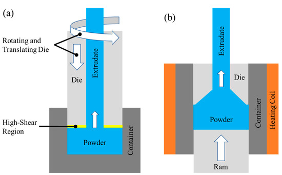
Figure 1.
Schematic of (a) friction extrusion and (b) hot extrusion on consolidated powders.
2.3. Sample Preparation and Characterization Methods
Both friction extrusion and hot extrusion specimens were cut along the longitudinal section using a diamond saw (Figure 2). Specimens for microstructural analyses were mounted in epoxy and polished to a final surface finish of 0.05 μm using colloidal silica. Optical microscopy (OM) was performed using an Olympus BX-51 fluorescence motorized microscope (Olympus, Tokyo, Japan). Scanning electron microscopy (SEM) analyses were performed using a JEOL 7600F field emission scanning electron microscope (JEOL, Tokyo, Japan) with energy-dispersive X-ray spectroscopy (EDS) using an accelerating voltage of 20 keV and a working distance of 10–15 mm. X-ray diffraction (XRD) (Bruker AXS Inc., Madison, WI, USA) was conducted on Al–12.4TM powders and Al–12.4TM extrudates to evaluate the evolution of second phases within the Al matrix. Tensile testing on extrudates at ambient and elevated temperatures was conducted according to ASTM E8 and ASTM E21, respectively, for friction-extruded and hot-extruded specimens.
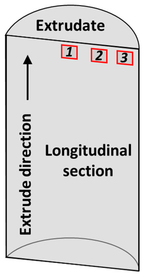
Figure 2.
Location of samples extracted from extrudates for microstructural characterization.
2.4. Equilibrium Thermodynamic Calculation
The experimentally observed phases obtained from the different extrusion methods are compared with the equilibrium phases calculated using the computational thermodynamic (CALculation of PHAse Diagrams, CALPHAD) approach. This comparison also takes advantage of input from the TCHEA3 database using Thermo-Calc software (TCHEA3, Thermo-Calc Software, Stockholm, Sweden).
3. Results and Discussion
3.1. Microstructural Investigation
OM images were taken from extrudates obtained via hot extrusion and friction extrusion to study the microstructural differences resulting from the two methods at different ERs (Figure 3). Extrudates made via hot extrusion with ER = 6 had inhomogeneous microstructures with narrow stringer-like features that averaged 50 µm wide and were highly elongated in the extrusion direction. These stringers form as powder particles and co-deform while being sheared in the extrusion direction. A detailed SEM analysis of stringer-like features is presented in the next section. Similar microstructural features are observed in hot-extruded specimens with ER = 25; however, the stringer-like features were observed to be much finer than that with ER = 6 (Figure 3(b1–b3)), with an average width of 5 µm. In addition, stringer-like features at the extrudate center (Location 1, as shown in Figure 3(a1)) are coarser than those at the extrudate periphery (Location 3, as shown in Figure 3(a3)) for ER = 6. This suggests that shear deformation is more severe at the extrudate periphery than at the center, as is common during extrusion. The resolution of OM is not high enough to reveal microstructural variances at ER = 25, which suggests that as expected, deformation becomes more severe as ER increases (e.g., roughly 4 times from ER = 6 to ER = 25). Although increasing by a factor of only 1.6, the microstructure of friction extrusion with ER = 40 is dramatically different compared to hot extrusion with ER = 25. For friction extrusion, the microstructure is also observed to be inhomogeneous but with a very different morphology than that which results from hot extrusion. Rather than the elongation of features in the extrusion direction, onion-ring-like features are observed at the center of friction-extruded material (Location 1, as shown in Figure 3(c1)). These features are created transverse to the extrusion direction by the combination of linear and rotational shear, which is a process that is intrinsic to friction extrusion, as the material enters the extrusion orifice. Similar features are commonly observed in friction stir welding and processing [26]. As shown in Figure 3(c2,c3), the microstructural features at locations that are radially outward from the centerline are more homogeneous.
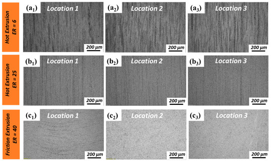
Figure 3.
Optical microscopy (OM) images of the longitudinal sections of specimens made by hot extrusion and friction extrusion: (a1–a3) hot extrusion made with extrusion ratio (ER) = 6; (b1–b3) hot extrusion made with ER = 25; and (c1–c3) friction extrusion made with ER = 40.
A more detailed microstructural analysis of the powder precursor, hot extrudates, and friction extrudates was conducted via SEM (Figure 4). Since there is no significantly evident microstructural difference between the center and periphery region for hot extrusions, only the center regions of hot extrusions were further investigated via SEM (Figure 4(b1–b3,c1–c3)). For friction extrusions, evident microstructural differences were observed with OM; therefore, both the center and periphery regions of friction extrusions were investigated via SEM (Figure 4(d1–d3,e1–e3)). The secondary phases (IMC phases) present in the starting powder display wide ranges of size and morphology due to variations in cooling rate across the spread of particle sizes, with chemistry and phase variety extensively characterized in prior work [17,18]. In general, the size of the IMC phases in the starting powders are larger than that in extruded materials due to refinement that occurs during shear deformation. For hot extrusions made with ER = 6 (Figure 4(b1–b3)), the size of the IMC phase is not homogenous. Secondary phases within the stringer-like features (marked with yellow arrows in Figure 4(b1)) are only slightly refined compared to the starting powder, while adjacent regions (marked with red arrows in Figure 4(b1) and shown with higher magnification in Figure 3(b3)) are highly refined compared to the starting powder. As for hot extrusions made with ER = 25, stringer-like features are no longer evident, and the entire microstructure is highly refined compared to the starting powder, as shown in Figure 4(c1–c3). For friction extrusion made with ER = 40, regions of lightly refined IMCs are observed as 5–25 µm thick bands that are oriented transverse to the extrusion direction and are labeled with yellow arrows in Figure 4(d1). Material adjacent to the transverse bands is observed to be highly refined compared to the starting powder. The secondary phases of friction-extruded material at Location 3 (Figure 4(e1–e3)) are highly refined compared to those at Location 1, which is along the centerline (as shown in Figure 4(d1–d3)). The thickness of the highly refined skin along the periphery of the extrusion has a thickness of approximately 500 µm. Areas of secondary phases in the periphery region of friction extrusions tend to be aligned with the extrusion direction, as shown in Figure 4(e2,e3). In prior work [18], it was found that friction-extruded Al–12.4TM powder had twice the ductility of hot-extruded material with ER = 6 and ER = 25 without a reduction in yield or ultimate strength. Using information obtained in the present analysis, we hypothesize that the highly refined skin developed during friction extrusion is effective at reducing stress concentrations that lead to an initiation of surface cracks, thereby improving elongation without sacrificing strength. At the center of a friction-extruded area, material primarily flows transverse to the extrusion direction; however, in the periphery region, material flow parallel to the extrusion direction is dominant. Some voids observed in hot extrusions are aligned parallel to the extrusion direction (labeled by red arrows in Figure 4(b1,c1)). Note that there is no evidence of voiding in the friction extrusions. This is likely due to the additional mixing provided by the rotational component of friction extrusion that is not present in hot extrusion. Voids vanishing in friction extrusions can be another factor of improved elongation.
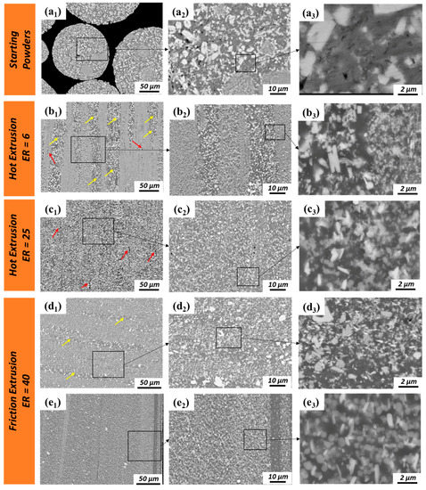
Figure 4.
SEM images of (a1–a3) Al–12.4TM starting powders and longitudinal sections of extrudates; (b1–b3) Location 1 of hot extrusion with ER = 6; (c1–c3) Location 1 of hot extrusion with ER = 25; (d1–d3) Location 1 and (e1–e3) Location 3 of friction extrusion with ER = 40. Note that the stringer and transverse onion-ring regions with large secondary phases are labeled with yellow arrows. Linear voids are labeled with red arrows. TM: transition metal.
To investigate the chemical composition distribution of the various secondary phases in the matrix, the staring powders and extrusions were examined used EDS. Figure 5(a1–a5) displays results for the starting Al–12.4TM powders that indicate two distinct IMC morphologies: equiaxed faceted particles and conjoined rectangular structures. Our previous transmission electron microscopy work [18] showed that the equiaxed faceted IMC phase that is rich in Fe and Cr and lean in Ti is a quasicrystal approximant (70.4 wt % Al, 20.4 wt % Fe, 8.7 wt % Cr, 0.6 wt % Ti) and that the conjoined rectangular IMC phase that is rich in Ti and Cr and lean in Fe is an Al3Ti-type structure (66.4 wt % Al, 28.8 wt % Ti, 4.7 wt % Cr). IMC phases comminuted during the processing of hot extrusion and friction extrusion, as shown in Figure 5(b1–b5,c1–c5,d1–d5,e1–e5). Fe and Cr tend to separate from each in smaller-scale features, forming one IMC phase that is rich in Fe and another IMC phase that is rich in Cr, as shown in Figure 5(c1–c5,e1–e5). Our previous work [18] suggested that the newly formed IMCs rich in Fe are based on an Al3.2Fe-type structure (65 wt % Al, 35 wt % Fe) and that the newly formed IMC rich in Cr could be the non-stoichiometric Al45Cr7-type structure (78 wt % Al, 11 wt % Cr, 9 wt % Fe, 2 wt % Ti). The phase separation tendencies of Fe and Cr in Fe–Cr, Fe–Cr–Al, and Fe–Cr–Al–Ti alloys at elevated temperatures [27,28,29] or under irradiation [30,31] have been previously reported, resulting in similar elemental separation. IMC phases with larger sizes (several microns) remain rich in both Fe and Cr (Figure 5(c1–c5,d1–d5)) while maintaining compositions similar to the starting powders. Al3Ti-type phases present in the powder precursor were fractured into finer particles during processing and, as a result of the nanoscale size of Ti (as shown in Figure 5(a5,b5,c5,d5,e5)), will likely dissolve into and perhaps precipitate out of the Al matrix during hot extrusion and friction extrusion. Furthermore, higher magnification SEM and EDS analyses of a selected region located within the friction extrusion center region (Figure 6) suggest that the initial stage of the phase transformation process occurs within the Al–Fe–Cr alloy system during friction extrusion. Figure 6 shows that the Fe-rich phase (labeled by black arrows) forms around the pre-existing quasicrystal approximant phase (70.4 wt % Al, 20.4 wt % Fe, 8.7 wt % Cr, 0.6 wt % Ti). By using the following thermal–mechanical cycle in the current alloy system, the quasicrystal approximant phases were further broken down along with phase transformation as verified in the periphery region of the friction extrusion (as shown in Figure 5(e1–e4)). Note that the mechanical effect in the thermal–mechanical cycle is more evident for the periphery region than for the center region of the friction extrusion.
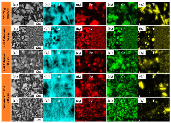
Figure 5.
Energy-dispersive X-ray spectroscopy (EDS) analysis of (a1–a5) Al–12.4TM starting powders and the longitudinal section of extrudates; (b1–b5) Location 1 of hot extrusion with ER = 6; (c1–c5) Location 1 of hot extrusion with ER = 25; (d1–d5) Location 1 and (e1–e5) Location 3 of friction extrusion with ER = 40.
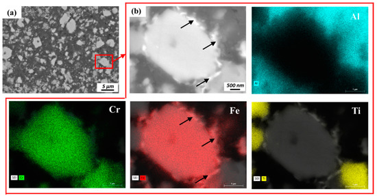
Figure 6.
(a) SEM and (b) EDS analyses reveal the phase separation of the quasicrystal approximant (70.4 wt % Al, 20.4 wt % Fe, 8.7 wt % Cr, 0.6 wt % Ti) into Fe-rich and Cr-rich phases.
The distinct crystal structures of the different IMC phases within starting powders and friction-extruded material were investigated by XRD analysis (Figure 7a–d). It was observed that the Al (Face Centered Cubic, FCC) phase dominates and that hexagonal Al3.2Fe, monoclinic Al45Cr7, and BCT Al3Ti are unambiguously indexed for friction extrusion. Note that the quasicrystal approximant phases (70.4 wt % Al, 20.4 wt % Fe, 8.7 wt % Cr, 0.6 wt % Ti) observed in starting powders are indexed as Al3.2Fe because they have similar lattice parameters. These observations are consistent with those reported earlier by Whalen et al. using transmission electron microscopy [18].
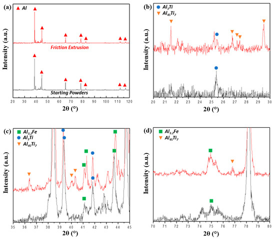
Figure 7.
XRD analysis of Al–12.4TM powders and friction extrusions with different ranges of 2θ: (a) 20°–120°, (b) 20°–30°, (c) 35°–45°, and (d) 70°–80°.
The equilibrium structure of the Al–12.4TM alloy is assessed using the Thermo-Calc TCHEA3 database. The equilibrium phase fraction in this alloy as a function of temperature is calculated and shown in Figure 8. The various IMCs within the alloy exhibit stability at temperatures up to ≈ 650 °C, beyond which the onset of liquation is observed. At room temperature, the molar fractions of different intermetallic phase structures calculated from equilibrium solution thermodynamics calculations are 50% Al13Fe4, 37% Al13Cr2, 11% FCC/L12, and 2% BCT/DO22. Other intermetallic phases, such as Al4Cr and Al11Cr2, are predicted to stabilize at high temperature of 600 °C. The Al13Fe4 phase predicted by CALPHAD is stoichiometrically close to the experimentally observed Al3.2Fe phase, and Al13Cr2 is stoichiometrically close to the Al45Cr7 phase that was experimentally identified in this work. A DO22 (Al3Ti) phase is observed both theoretically as well as experimentally. Interestingly, the equilibrium fraction of the Al (FCC) phase is predicted to be low, which is inconsistent with our experimental findings. The experimental results show that the matrix Al (FCC) phase forms the major phase of the microstructure, which could be a result of the slow kinetics growth and coarsening of the multiple intermetallic phases. The thermodynamic calculations predict the type of equilibrium phases; however, our current extrusion processes do not result in an equilibrium phase because of the severe straining and insufficient annealing times required to reach equilibrium. Moreover, these compositionally conjugate intermetallic phases can interpenetrate with each other and therefore reduce the kinetics for coarsening.
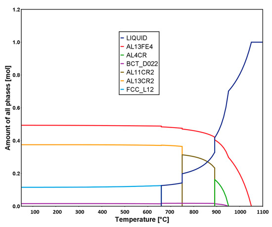
Figure 8.
Calculated molar fraction of equilibrium phases as a function of the temperature for the Al–12.TM alloy used in this study.
3.2. Mechanical Response Characterization
To compare the mechanical responses of various aluminum alloys at different temperatures, an Ashby plot was constructed to compare the ultimate tensile strength of commercially available Al–12.4TM as a function of temperature with other commercially available aluminum alloys (Figure 9). Note that the temperature at which the strength starts to fall sharply is defined as the maximum service temperature. Figure 9 shows that the maximum service temperature of most aluminum alloys is less than ≈200 °C except for the AA8009 alloy, which is a rapidly solidified Al–TM alloy with a chemical composition of Al–Fe–Si–V. At a service temperature of 250–300 °C, the only commercially available alloy with a higher tensile strength than Al–12.4TM that the authors are aware of is AA8009 (labeled in Figure 9).
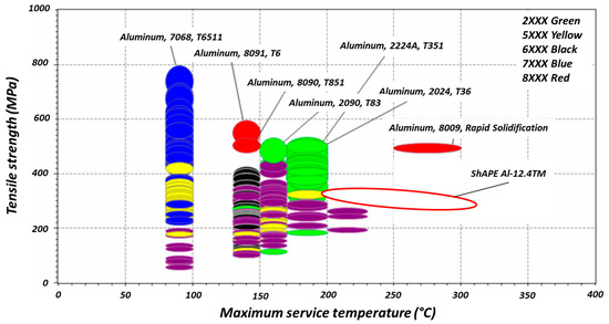
Figure 9.
A comparison of the tensile strengths of various aluminum alloys at elevated temperatures.
The tensile strengths and elongations at elevated temperatures of various Al–TM alloys produced by rapid solidification are compared with friction extrusion and hot extrusion in Figure 10. As shown in Figure 10, the tensile strength of the Al–12.4TM alloy fabricated via hot and friction extrusions is comparable to other Al–TM alloys made via rapid solidification methods. Furthermore, ambient temperature elongation of an Al–12.4TM alloy fabricated through friction extrusion is enhanced significantly compared to that of Al–TM alloys produced through rapid solidification or hot extrusion methods (Figure 11). Note that the elongation of rapidly solidified Al–TM alloys increases with temperature, and surprisingly, the elongation of Al–12.4TM fabricated via friction extrusion decreased as temperature increased. The mechanism of ductility loss at elevated temperature of friction extruded Al-12.4TM alloy is unclear and is currently being investigated.
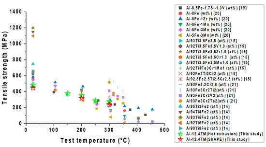
Figure 10.
Comparison of the tensile strengths of various Al–TM alloys at elevated temperatures.
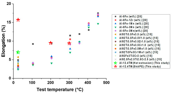
Figure 11.
Comparison of elongation for various Al–TM alloys at elevated temperatures.
4. Conclusions
- For hot extrusion, deformation at the extrusion periphery region is more severe than at the extrusion center region. While for friction extrusion, material flow perpendicular to the extrusion direction is dominant at the center region, and material flow parallel to the extrusion direction is dominant at the extrusion periphery region.
- Friction-extruded Al–12.4TM has a comparable strength (>200 MPa at 300 °C) but a higher ductility (>15% at ambient temperature) than hot-extruded Al–12.4TM. This is likely due to the elimination of voiding and finer second phases, which is enabled by the additional high-shear component introduced during friction extrusion.
- During extrusion, the quasicrystal approximant IMC phase (70.4 wt % Al, 20.4 wt % Fe, 8.7 wt % Cr, 0.6 wt % Ti) was broken into small pieces. Fe and Cr tend to separate from each other, forming new IMC phases of the Al3.2Fe–type (65 wt % Al, 35 wt % Fe) and non-stoichiometric Al45Cr7-type structures (78 wt % Al, 11 wt % Cr, 9 wt % Fe, 2 wt % Ti).
- The rectangular IMC phases (66.4 wt % Al, 28.8 wt % Ti, 4.7 wt % Cr) with Al3Ti-type structures in the powder precursor break into small pieces and are dissolved into the Al matrix during hot extrusion and friction extrusion processes.
- A fine-scale distribution of multiple intermetallic phases is achieved in this material using friction extrusion. The competition of coarsening at the interfaced between these precipitates pins them and restricts their extent of coarsening even at high temperature.
Author Contributions
Conceptualization, S.W.; Methodology, T.W., B.G., J.S., J.D., T.R. and A.O.; Data analysis, T.W., B.G., J.S., J.D., T.R. and A.O.; Writing—original draft preparation, T.W. and B.G.; Writing—review and editing, S.W., W.D. and T.P.; Supervision, S.W. and S.J.; Project administration, S.W. and S.J.; Funding acquisition, S.W. All authors have read and agreed to the published version of the manuscript.
Funding
PNNL is operated by Battelle Memorial Institute for the U.S. Department of Energy under contract DE-AC05-76RL01830. This work was sponsored by the U.S. Department of Energy Office of Technology Transitions. The authors would like to thank Anthony Guzman for assistance in sample preparation.
Data Availability Statement
The raw and processed data required to reproduce these findings cannot currently be shared as a result of technical limitations and developing intellectual property.
Conflicts of Interest
The views and opinions of the authors expressed herein do not necessarily state or reflect those of the United States Government or any agency thereof. Neither the United States Government nor any agency thereof, nor any of their employees, makes any warranty, expressed or implied, or assumes any legal liability or responsibility for the accuracy, completeness, or usefulness of any information, apparatus, product, or process disclosed, or represents that its use would not infringe privately owned rights. The authors declare no conflict of interest.
References
- Davis, J.R. Aluminum and Aluminum Alloys; ASM International: Cleveland, OH, USA, 1993; pp. 351–416. [Google Scholar]
- Miller, W.S.; Zhuang, L.; Bottema, J.; Wittebrood, A.; De Smet, P.; Haszler, A.; Vieregge, A.J.M.S. Recent development in aluminium alloys for the automotive industry. Mater. Sci. Eng. A 2000, 280, 37–49. [Google Scholar] [CrossRef]
- Rambabu, P.P.N.K.V.; Prasad, N.E.; Kutumbarao, V.V.; Wanhill, R.J.H. Aluminium alloys for aerospace applications. In Aerospace Materials and Material Technologies; Springer: Berlin, German, 2017; pp. 29–52. [Google Scholar]
- Kaufman, J.G. Properties and Characteristics of Aluminum and Aluminum Alloys; ASM International: Geauga, OH, USA, 2016; pp. 1–9. [Google Scholar]
- Mishra, R.S.; Ma, Z.Y. Friction stir welding and processing. Mater. Sci. Eng. R 2005, 50, 1–78. [Google Scholar]
- Shyam, A.; Roy, S.; Shin, D.; Poplawsky, J.D.; Allard, L.F.; Yamamoto, Y.; Morris, J.R.; Mazumder, B.; Idrobo, J.C.; Rodriguez, A.; et al. Elevated temperature microstructural stability in cast AlCuMnZr alloys through solute segregation. Mater. Sci. Eng. A 2019, 765, 138279. [Google Scholar] [CrossRef]
- Harada, Y.; Dunand, D.C. Thermal expansion of Al3Sc and Al3(Sc0.75X0.25). Scr. Materialia 2003, 48, 219–222. [Google Scholar] [CrossRef]
- Blake, N.; Hopkins, M.A. Constitution and age hardening of Al-Sc alloys. J. Mater. Sci. 1985, 20, 2861–2867. [Google Scholar] [CrossRef]
- Norman, A.F.; Prangnell, P.B.; McEwen, R.S. The solidification behaviour of dilute aluminium-scandium alloys. Acta Mater. 1998, 46, 5715–5732. [Google Scholar] [CrossRef]
- Røyset, J.; Ryum, N. Kinetics and mechanisms of precipitation in an Al-0.2 wt.% Sc alloy. Mater. Sci. Eng. A 2005, 396, 409–422. [Google Scholar]
- Seibold, A. Phase equilibria in the ternary system Ti-Fe-O and Ti-Al-Fe. Z. Met. 1981, 72, 712–719. [Google Scholar]
- Wagner, C. Theory of precipitate change by redissolution. Z. Elektrochem. 1961, 65, 581–591. [Google Scholar]
- Skinner, D.J.; Bye, R.L.; Raybould, D.; Brown, A.M. Dispersion strengthened Al-Fe-V-Si alloys. Scr. Metall. 1986, 20, 867–872. [Google Scholar] [CrossRef]
- Kimura, H.; Sasamori, K.; Inoue, A. High strength Al-Ti-Fe alloys consisting of amorphous and fcc-Al phases prepared by rapid solidification. Mater. Trans. JIM 1996, 37, 1722–1725. [Google Scholar] [CrossRef][Green Version]
- Kawamura, Y.; Inoue, A.; Takagi, M.; Ohta, H.; Imura, T.; Masumoto, T. Rapidly solidified powder metallurgy of Al-Ti-Fe-X alloys. Scr. Mater. 1999, 40, 1131–1137. [Google Scholar]
- Zawrah, M.; Shaw, L. Microstructure and hardness of nanostructured Al-Fe-Cr-Ti alloys through mechanical alloying. Mater. Sci. Eng. A 2003, 355, 37–49. [Google Scholar] [CrossRef]
- Daye, W.K.; Pelletiers, I.; Thomas, W. Property development of new generation pm aluminum materials via innovative processing. Int. J. Powder Metall. 2018, 54, 35–51. [Google Scholar]
- Whalen, S.; Olszta, M.; Roach, C.; Darsell, J.; Graff, D.; Reza-E-Rabby, M.; Roosendaal, T.; Daye, W.; Pelletiers, T.; Mathaudhu, S.; et al. High ductility aluminum alloy made from powder by friction extrusion. Materialia 2019, 6, 100260. [Google Scholar] [CrossRef]
- Ellis, M.B.D.; Strangwood, M. Welding of rapidly solidified Alloy 8009 (Al-8·5Fe-1·7Si-1·3V): Preliminary study. Mater. Sci. Tech. Lond. 1996, 12, 970–977. [Google Scholar] [CrossRef]
- Thursfield, G.; Stowell, M.J. Mechanical properties of Al-8 wt.% Fe-based alloys prepared by rapid quenching from the liquid state. J. Mater. Sci. 1974, 9, 1644–1660. [Google Scholar] [CrossRef]
- Galano, M.; Audebert, F.; Escorial, A.G.; Stone, I.C.; Cantor, B. Nanoquasicrystalline Al-Fe-Cr-based alloys. Part II. Mechanical properties. Acta Mater. 2009, 57, 5120–5130. [Google Scholar] [CrossRef]
- Overmana, N.R.; Whalena, S.A.; Bowdenab, M.E.; Olsztaa, M.J.; Kruskaa, K.; Clarkc, T.; Stevensd, E.L.; Darsella, J.T.; Joshia, V.V.; Jianga, X.; et al. Homogenization and texture development in rapidly solidified AZ91E consolidated by Shear Assisted Processing and Extrusion (ShAPE). Mater. Sci. Eng. A 2017, 701, 56–68. [Google Scholar] [CrossRef]
- Darsell, J.T.; Overman, N.R.; Joshi, V.V.; Whalen, S.A.; Mathaudhu, S.N. Shear Assisted Processing and Extrusion (ShAPE™) of AZ91E Flake: A study of tooling features and processing effects. J. Mater. Eng. Perform. 2018, 27, 4150–4161. [Google Scholar] [CrossRef]
- Whalen, S.; Joshi, V.; Overman, N.; Caldwell, D.; Lavender, C.; Skszek, T. Scaled-up fabrication of thin-walled ZK60 tubing using shear assisted processing and extrusion (ShAPE). In Magnesium Technology; Springer: Berlin, German, 2017; pp. 315–321. [Google Scholar]
- Whalen, S.; Overman, N.; Joshi, V.; Varga, T.; Graff, D.; Lavender, C. Magnesium alloy ZK60 tubing made by Shear Assisted Processing and Extrusion (ShAPE). Mater. Sci. Eng. A 2019, 755, 278–288. [Google Scholar] [CrossRef]
- Krishnan, K.N. On the formation of onion rings in friction stir welds. Mater. Sci. Eng. A 2002, 327, 246–251. [Google Scholar] [CrossRef]
- Capdevila, C.; Miller, M.K.; Russell, K.F. Aluminum partitioning during phase separation in Fe-20% Cr-6% Al ODS alloy. J. Mater. Sci. 2008, 43, 3889–3893. [Google Scholar] [CrossRef]
- Kuronen, A.; Granroth, S.; Heinonen, M.H.; Perälä, R.E.; Kilpi, T.; Laukkanen, P.; Lång, J.; Dahl, J.; Punkkinen, M.P.J.; Kokko, K.; et al. Segregation, precipitation, and α-α′ phase separation in Fe-Cr alloys. Phys. Rev. B 2015, 92, 214113. [Google Scholar]
- Airiskallio, E.; Nurmi, E.; Heinonen, M.H.; Väyrynen, I.J.; Kokko, K.; Ropo, M.; Punkkinen, M.P.J.; Pitkänen, H.; Alatalo, M.; Kollár, J.; et al. Third element effect in the surface zone of FeCr-Al alloys. Phys. Rev. B 2010, 81, 033105. [Google Scholar]
- Terentyev, D.; Bergner, F.; Osetsky, Y. Cr segregation on dislocation loops enhances hardening in ferritic Fe-Cr alloys. Acta Mater. 2013, 61, 1444–1453. [Google Scholar] [CrossRef]
- Choudhury, S.; Barnard, L.; Tucker, J.D.; Allen, T.R.; Wirth, B.D.; Asta, M.; Morgan, D. Ab-initio based modeling of diffusion in dilute bcc Fe-Ni and Fe-Cr alloys and implications for radiation induced segregation. J. Nucl. Mater. 2011, 411, 1–14. [Google Scholar] [CrossRef]


Publisher’s Note: MDPI stays neutral with regard to jurisdictional claims in published maps and institutional affiliations. |
© 2020 by the authors. Licensee MDPI, Basel, Switzerland. This article is an open access article distributed under the terms and conditions of the Creative Commons Attribution (CC BY) license (http://creativecommons.org/licenses/by/4.0/).