Faraday Rotation of Dy2O3, CeF3 and Y3Fe5O12 at the Mid-Infrared Wavelengths

 ,
,  , , , and
Abstract
1. Introduction
2. Methods of investigation
2.1. Fabrication Process of DyO Ceramics and Sample Parameters
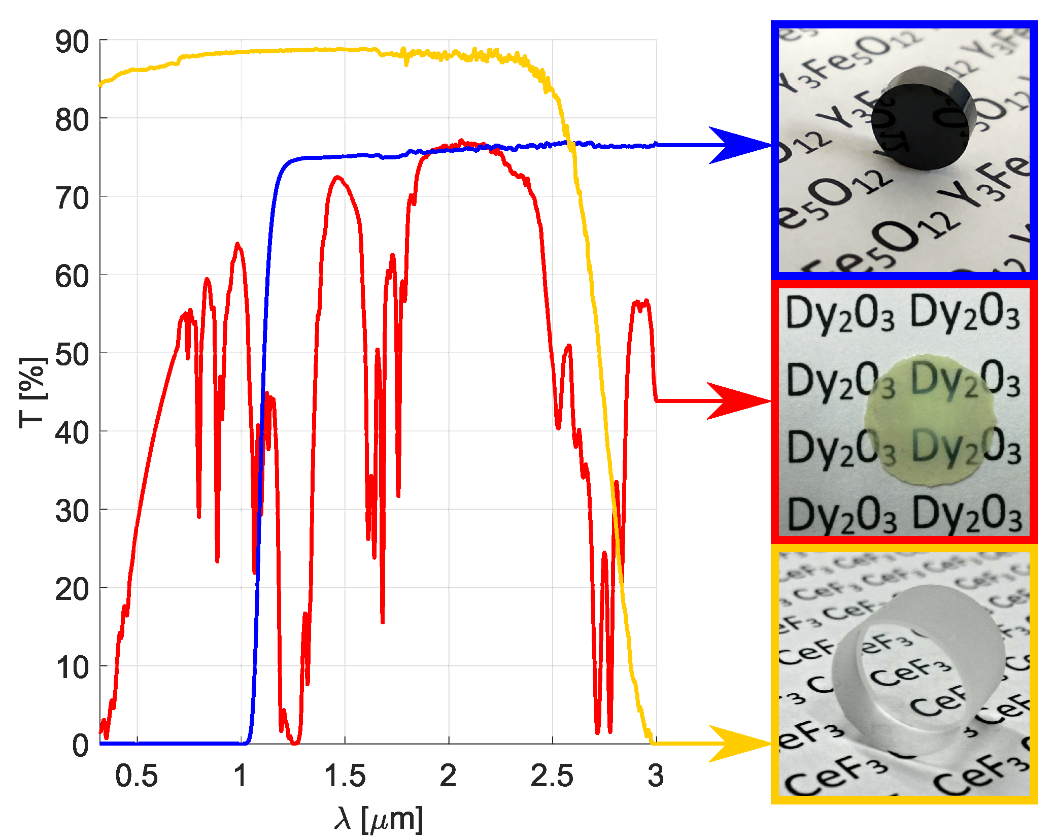
2.2. Optical Transmittance Measurement
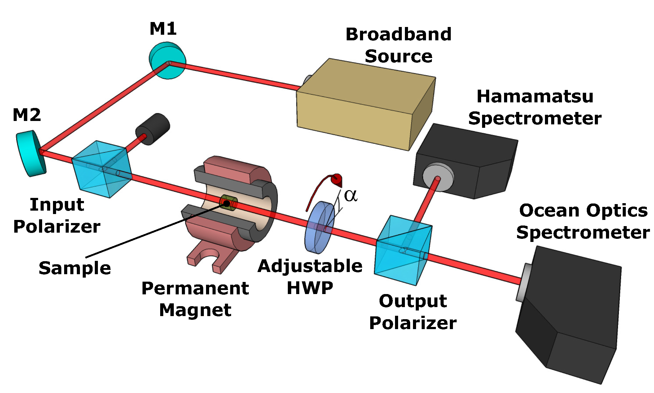
2.3. Faraday Rotation Dispersion Measurement
2.4. Faraday Rotation in the Linear and in the Saturated Regime of the Faraday Effect
2.5. Model Functions for the Faraday Rotation Dispersion
2.5.1. CeF Crystal
2.5.2. DyO Ceramics
2.5.3. YIG Crystal
3. Results
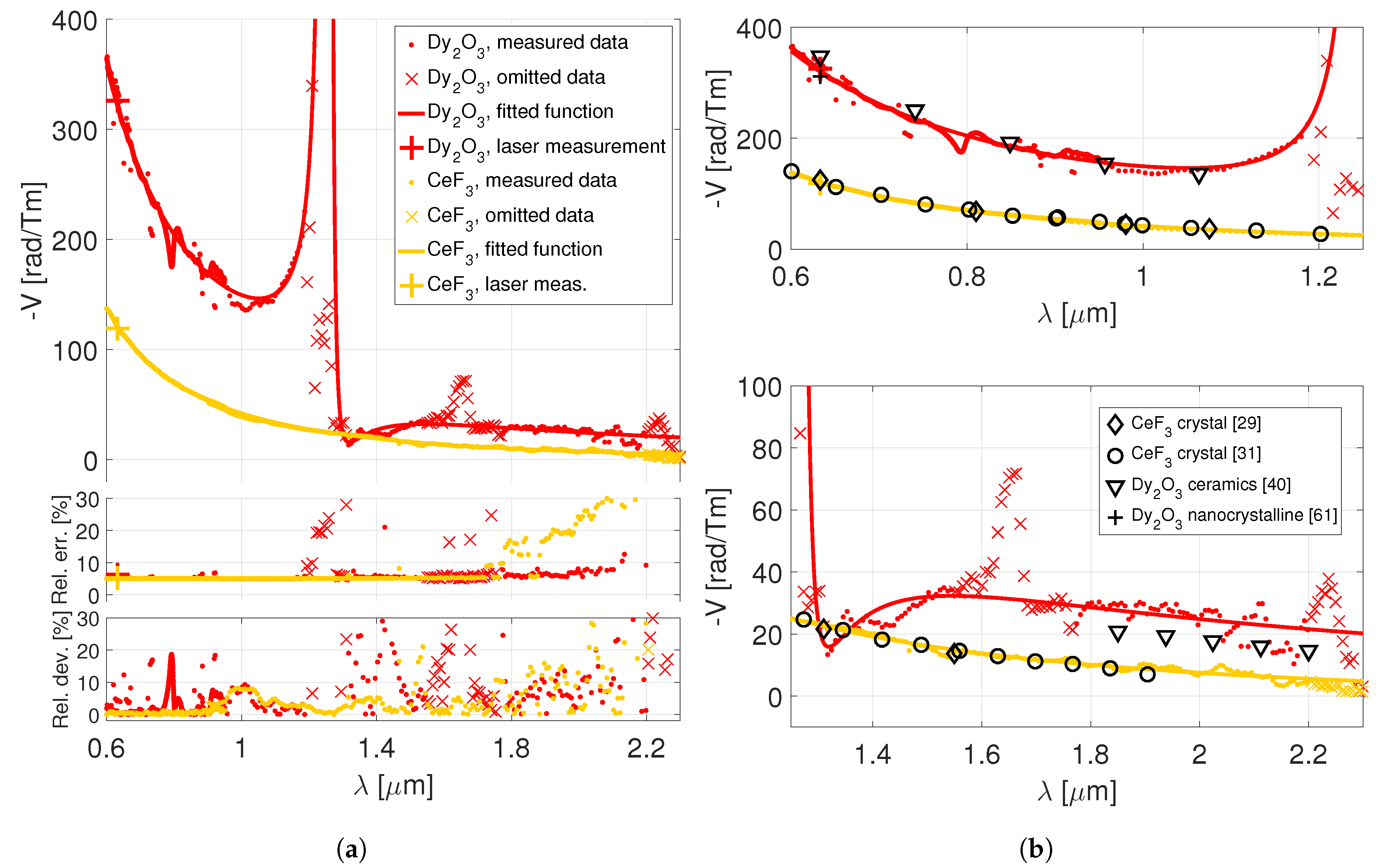
3.1. DyO Ceramics and CeF Crystal
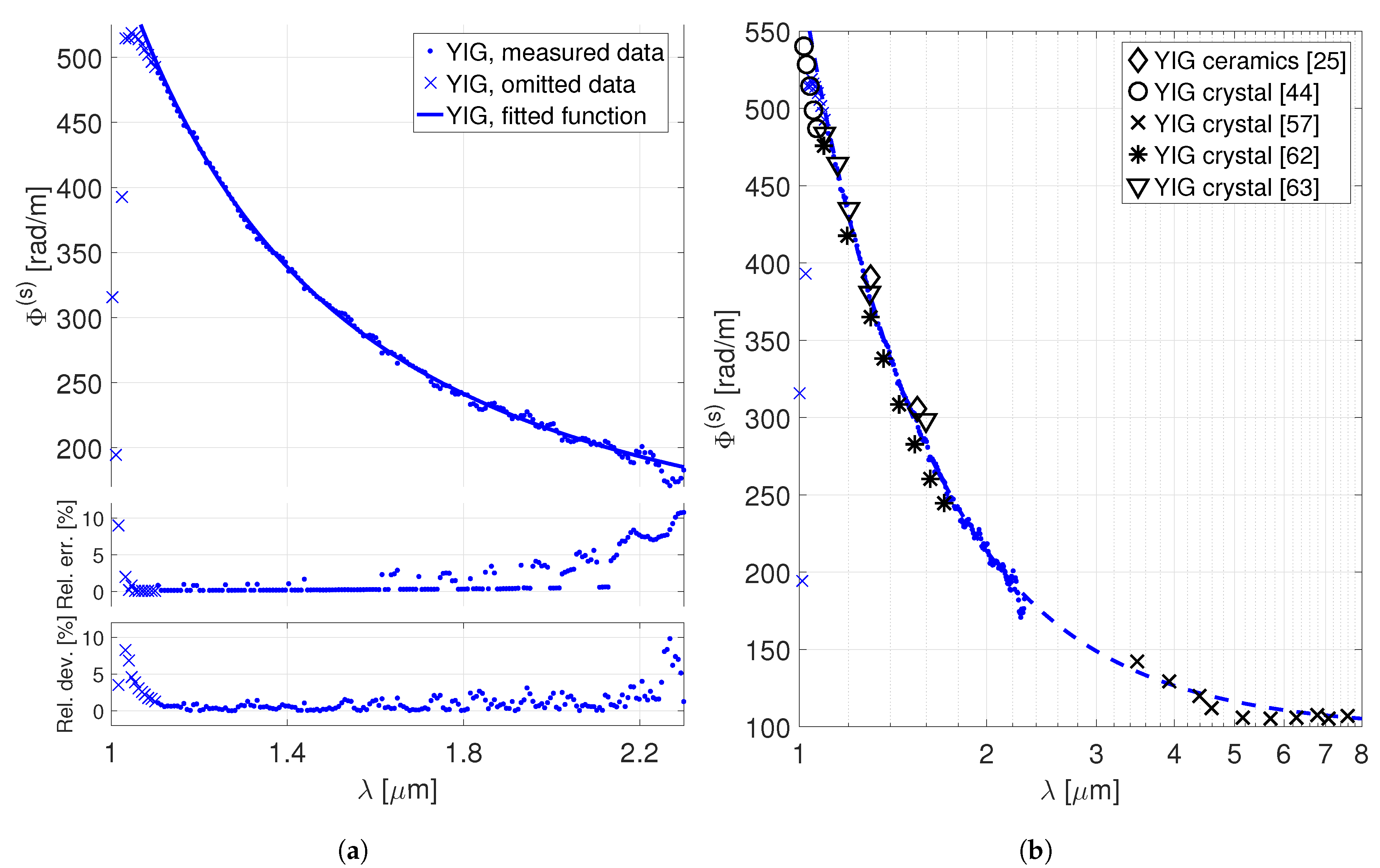
3.2. YIG Crystal
4. Discussion
5. Conclusions
- has a transparency window, and, hence, may be used for constructing Faraday devices for the 2- lasers. The material is paramagnetic, which implies it may be used in the linear regime of the Faraday effect and tune the desired rotation angle by the strength of the applied magnetic field.
- exhibit a ∼27–20 rad/Tm (in the absolute value) Verdet constant in the spectral region. This will allow using the currently commercially available permanent magnets to achieve the standardly needed Faraday rotation angles after the ceramics fabrication process will be optimized.
- is transparent up to 2.5 and, therefore, it may be also used for the 2- Faraday devices. Similarly to DyO, the material is paramagnetic.
- has a ∼9–5 rad/Tm (in the absolute value) Verdet constant in the spectral region. Relatively strong magnetic fields or multiple magneto-optical elements would be needed to achieve the standardly needed Faraday rotation angles using the CeF crystal, nevertheless, the technology to fabricate this material in large sizes is already available [65].
- has a wide transparency window from 1 to 5 , and, therefore, represents a universal Faraday material choice for the whole mid-IR spectral region. Its ferrimagnetic nature implies the convenience of its operation in the saturated regime in the Faraday devices. Then, the desired rotation angle is tuned by adjusting the length of the magneto-optical element.
- has a 232–185 rad/m saturated specific Faraday rotation in the spectral region, which, considering the material’s low saturation magnetization, enables using a relatively weak and compact magnet to achieve the needed Faraday rotation. The material is commercially available in small-scale sizes with a prospect of fabrication of larger-scale samples in the form of transparent ceramics in the near future.
- Specific Faraday rotation dispersion data in the 2- spectral region may be described (with a < accuracy) by a proposed model (8) with the parameters listed in Section 3.2. The model approximates the contributions of the Fe ions’ multiple electric dipole transitions distributed in the UV region using a single diamagnetic term with an effective transition wavelength at . The values given by this simplified model exhibit a < agreement with the yet-reported literature values in the <, as well as in the extrapolated > spectral regions. Although the understanding of the YIG’s UV transitions is not complete, we believe that the proposed model may serve, at least, as a rough approximation of the material’s specific Faraday rotation in the saturated regime over the whole mid-IR spectral region.
Author Contributions
Funding
Conflicts of Interest
References
- Scholle, K.; Lamrini, S.; Koopmann, P.; Fuhrberg, P. 2 μm Laser Sources and Their Possible Applications. In Frontiers in Guided Wave Optics and Optoelectronics; InTech: London, UK, 2010. [Google Scholar] [CrossRef]
- Leindecker, N.; Marandi, A.; Byer, R.L.; Vodopyanov, K.L.; Jiang, J.; Hartl, I.; Fermann, M.; Schunemann, P.G. Octave-spanning ultrafast OPO with 2.6–6.1 μm instantaneous bandwidth pumped by femtosecond Tm-fiber laser. Opt. Express 2012, 20, 7046–7053. [Google Scholar] [CrossRef] [PubMed]
- Du, Z.; Zhang, S.; Li, J.; Gao, N.; Tong, K.; Du, Z.; Zhang, S.; Li, J.; Gao, N.; Tong, K. Mid-Infrared Tunable Laser-Based Broadband Fingerprint Absorption Spectroscopy for Trace Gas Sensing: A Review. Appl. Sci. 2019, 9, 338. [Google Scholar] [CrossRef]
- Popmintchev, T.; Chen, M.C.; Arpin, P.; Murnane, M.M.; Kapteyn, H.C. The attosecond nonlinear optics of bright coherent X-ray generation. Nat. Photonics 2010, 4, 822–832. [Google Scholar] [CrossRef]
- Weisshaupt, J.; Juvé, V.; Holtz, M.; Ku, S.; Woerner, M.; Elsaesser, T.; Ališauskas, S.; Pugžlys, A.; Baltuška, A. High-brightness table-top hard X-ray source driven by sub-100-femtosecond mid-infrared pulses. Nat. Photonics 2014, 8, 927–930. [Google Scholar] [CrossRef]
- Leshchenko, V.E.; Talbert, B.K.; Lai, Y.H.; Li, S.; Tang, Y.; Hageman, S.J.; Smith, G.; Agostini, P.; DiMauro, L.F.; Blaga, C.I. High-power few-cycle Cr:ZnSe mid-infrared source for attosecond soft x-ray physics. Optica 2020, 7, 981–988. [Google Scholar] [CrossRef]
- Danson, C.N.; Haefner, C.; Bromage, J.; Butcher, T.; Chanteloup, J.C.F.; Chowdhury, E.A.; Galvanauskas, A.; Gizzi, L.A.; Hein, J.; Hillier, D.I.; et al. Petawatt and exawatt class lasers worldwide. High Power Laser Sci. Eng. 2019, 7, e54. [Google Scholar] [CrossRef]
- Fortin, V.; Bernier, M.; Caron, N.; Faucher, D.; El Amraoui, M.; Messaddeq, Y.; Vallée, R. Towards the development of fiber lasers for the 2 to 4 μ m spectral region. Opt. Eng. 2013, 52, 054202. [Google Scholar] [CrossRef]
- Zhu, X.; Zhu, G.; Wei, C.; Kotov, L.V.; Wang, J.; Tong, M.; Norwood, R.A.; Peyghambarian, N. Pulsed fluoride fiber lasers at 3 μm [Invited]. J. Opt. Soc. Am. B 2017, 34, A15–A28. [Google Scholar] [CrossRef]
- Jelínkova, H.; Doroshenko, M.E.; Osiko, V.V.; Jelínek, M.; Šulc, J.; Němec, M.; Vyhlídal, D.; Badikov, V.V.; Badikov, D.V. Dysprosium thiogallate laser: Source of mid-infrared radiation at 2.4, 4.3, and 5.4 μm. Appl. Phys. A Mater. Sci. Process. 2016, 122, 738. [Google Scholar] [CrossRef]
- Doroshenko, M.E.; Jelínková, H.; Jelínek, M.; Šulc, J.; Vyhlídal, D.; Kovalenko, N.O.; Terzin, I.S. Room temperature Fe2+:Cd1-xMnxTe laser generating at 5.4–6 μm. Opt. Lett. 2018, 43, 5058–5061. [Google Scholar] [CrossRef]
- Švejkar, R.; Šulc, J.; Jelínková, H. Er-doped crystalline active media for 3 μm diode-pumped lasers. Prog. Quantum Electron. 2020, 74, 100276. [Google Scholar] [CrossRef]
- Zvezdin, A.K.; Kotov, V.A. Modern Magnetooptics and Magnetooptical Materials, 1st ed.; Taylor & Francis Group: New York, NY, USA, 1997; pp. 1–109. [Google Scholar]
- Weber, M.J. Faraday Rotator Materials For Laser Systems. In Proceedings of the 30th Annual Technical Symposium, Laser and Nonlinear Optical Materials, San Diego, CA, USA, 1–3 August 1986; SPIE: San Diego, CA, USA, 1987; Volume 0681, pp. 75–90. [Google Scholar] [CrossRef]
- Huynh, J.; Smrž, M.; Miura, T.; Slezák, O.; Vojna, D.; Čech, M.; Endo, A.; Mocek, T. Femtosecond Yb:YGAG ceramic slab regenerative amplifier. Opt. Mater. Express 2018, 8, 615–621. [Google Scholar] [CrossRef]
- Khazanov, E. Thermooptics of magnetoactive medium: Faraday isolators for high average power lasers. Uspekhi Fiz. Nauk 2016, 186, 975–1000. [Google Scholar] [CrossRef]
- Snetkov, I.L. Features of Thermally Induced Depolarization in Magneto-Active Media With Negative Optical Anisotropy Parameter. IEEE J. Quantum Electron. 2018, 54, 1–8. [Google Scholar] [CrossRef]
- Vojna, D.; Slezák, O.; Lucianetti, A.; Mocek, T. Verdet Constant of Magneto-Active Materials Developed for High-Power Faraday Devices. Appl. Sci. 2019, 9, 3160. [Google Scholar] [CrossRef]
- Slezak, O.; Yasuhara, R.; Lucianetti, A.; Vojna, D.; Mocek, T. Thermally induced depolarization in terbium gallium garnet ceramics rod with natural convection cooling. J. Opt. 2015, 17, 065610. [Google Scholar] [CrossRef]
- Snetkov, I.L.; Yasuhara, R.; Starobor, A.V.; Mironov, E.A.; Palashov, O.V. Thermo-Optical and Magneto-Optical Characteristics of Terbium Scandium Aluminum Garnet Crystals. IEEE J. Quantum Electron. 2015, 51, 1–7. [Google Scholar] [CrossRef]
- Karimov, D.N.; Sobolev, B.P.; Ivanov, I.A.; Kanorsky, S.I.; Masalov, A.V. Growth and magneto-optical properties of Na0.37Tb0.63F2.26 cubic single crystal. Crystallogr. Rep. 2014, 59, 718–723. [Google Scholar] [CrossRef]
- Vojna, D.; Duda, M.; Yasuhara, R.; Slezák, O.; Schlichting, W.; Stevens, K.; Chen, H.; Lucianetti, A.; Mocek, T. Verdet constant of potassium terbium fluoride crystal as a function of wavelength and temperature. Opt. Lett. 2020, 45, 1683–1686. [Google Scholar] [CrossRef]
- Ikesue, A.; Aung, Y.; Makikawa, S.; Yahagi, A. Total Performance of Magneto-Optical Ceramics with a Bixbyite Structure. Materials 2019, 12, 421. [Google Scholar] [CrossRef]
- Sekijima, T.; Kishimoto, H.; Fujii, T.; Wakino, K.; Okada, M. Magnetic, Optical and Microwave Properties of Rare-Earth-Substituted Fibrous Yttrium Iron Garnet Single Crystals Grown by Floating Zone Method. Jpn. J. Appl. Phys. 1999, 38, 5874–5878. [Google Scholar] [CrossRef]
- Ikesue, A.; Aung, Y.L. Development of optical grade polycrystalline YIG ceramics for faraday rotator. J. Am. Ceram. Soc. 2018, 101, 5120–5126. [Google Scholar] [CrossRef]
- Aung, Y.L.; Ikesue, A.; Watanabe, T.; Makikawa, S.; Iwamoto, Y. Bi substituted YIG ceramics isolator for optical communication. J. Alloys Compd. 2019, 811, 152059. [Google Scholar] [CrossRef]
- Ikesue, A.; Aung, Y.; Yasuhara, R.; Iwamoto, Y. Giant Faraday rotation in heavily ce-doped YIG bulk ceramics. J. Eur. Ceram. Soc. 2020, 40, 6073–6078. [Google Scholar] [CrossRef]
- Vasyliev, V.; Villora, E.G.; Nakamura, M.; Sugahara, Y.; Shimamura, K. UV-visible Faraday rotators based on rare-earth fluoride single crystals: LiREF4 (RE = Tb, Dy, Ho, Er and Yb), PrF3 and CeF3. Opt. Express 2012, 20, 14460–14470. [Google Scholar] [CrossRef]
- Mironov, E.A.; Starobor, A.V.; Snetkov, I.L.; Palashov, O.V.; Furuse, H.; Tokita, S.; Yasuhara, R. Thermo-optical and magneto-optical characteristics of CeF3 crystal. Opt. Mater. 2017, 69, 196–201. [Google Scholar] [CrossRef]
- Starobor, A.; Mironov, E.; Snetkov, I.; Palashov, O.; Furuse, H.; Tokita, S.; Yasuhara, R. Cryogenically cooled CeF3 crystal as media for high-power magneto-optical devices. Opt. Lett. 2017, 42, 1864–1866. [Google Scholar] [CrossRef]
- Vojna, D.; Yasuhara, R.; Slezák, O.; Mužík, J.; Lucianetti, A.; Mocek, T. Verdet constant dispersion of CeF3 in the visible and near-infrared spectral range. Opt. Eng. 2017, 56, 067105. [Google Scholar] [CrossRef]
- Starobor, A.V.; Mironov, E.A.; Palashov, O.V. Thermal lens in magneto-active fluoride crystals. Opt. Mater. 2019, 98, 109469. [Google Scholar] [CrossRef]
- Snetkov, I.L.; Yakovlev, A.I.; Permin, D.A.; Balabanov, S.S.; Palashov, O.V. Magneto-optical Faraday effect in dysprosium oxide (Dy2O3) based ceramics obtained by vacuum sintering. Opt. Lett. 2018, 43, 4041–4044. [Google Scholar] [CrossRef]
- Mironov, E.; Palashov, O.; Karimov, D. EuF2-based crystals as media for high-power mid-infrared Faraday isolators. Scr. Mater. 2019, 162, 54–57. [Google Scholar] [CrossRef]
- Mollaee, M.; Zhu, X.; Jenkins, S.; Zong, J.; Temyanko, E.; Norwood, R.; Chavez-Pirson, A.; Li, M.; Zelmon, D.; Peyghambarian, N. Magneto-optical properties of highly Dy3+ doped borate glasses. Opt. Express 2020, 28, 11789–11796. [Google Scholar] [CrossRef] [PubMed]
- Mollaee, M.; Lucas, P.; Ari, J.; Zhu, X.; Lukowski, M.; Manzur, T.; Peyghambarian, N. High Verdet constant of Te20 As30Se50 glass in the mid-infrared. Opt. Lett. 2020, 45, 2183–2186. [Google Scholar] [CrossRef] [PubMed]
- Mukhin, I.; Voitovich, A.; Palashov, O.; Khazanov, E. 2.1 Tesla permanent-magnet Faraday isolator for subkilowatt average power lasers. Opt. Commun. 2009, 282, 1969–1972. [Google Scholar] [CrossRef]
- Mironov, E.A.; Snetkov, I.L.; Voitovich, A.V.; Palashov, O.V. Permanent-magnet Faraday isolator with the field intensity of 25 kOe. Quantum Electron. 2013, 43, 740–743. [Google Scholar] [CrossRef]
- Mironov, E.A.; Voitovich, A.V.; Palashov, O.V. Permanent-magnet Faraday isolator with the field intensity of more than 3 tesla. Laser Phys. Lett. 2020, 17, 015001. [Google Scholar] [CrossRef]
- Slezák, O.; Yasuhara, R.; Vojna, D.; Furuse, H.; Lucianetti, A.; Mocek, T. Temperature-wavelength dependence of Verdet constant of Dy2O3 ceramics. Opt. Mater. Express 2019, 9, 2971–2981. [Google Scholar] [CrossRef]
- Vojna, D.; Yasuhara, R.; Furuse, H.; Slezak, O.; Hutchinson, S.; Lucianetti, A.; Mocek, T.; Cech, M. Faraday effect measurements of holmium oxide (Ho2O2) ceramics-based magneto-optical materials. High Power Laser Sci. Eng. 2018, 6, e2. [Google Scholar] [CrossRef]
- Hansen, P.; Krumme, J.P. Magnetic and magneto-optical properties of garnet films. Thin Solid Film. 1984, 114, 69–107. [Google Scholar] [CrossRef]
- Scott, G.B.; Lacklison, D.E.; Page, J.L. Absorption spectra of Y3Fe5O12 (YIG) and Y3Ga5O12: Fe3+. Phys. Rev. B 1974, 10, 971–986. [Google Scholar] [CrossRef]
- Andlauer, B.; Schneider, J.; Wettling, W. Optical and magneto-optical properties of YIG and FeBO3. Appl. Phys. 1976, 10, 189–201. [Google Scholar] [CrossRef]
- Kawase, H.; Yasuhara, R. 2.92-μm high-efficiency continuous-wave laser operation of diode-pumped Er:YAP crystal at room temperature. Opt. Express 2019, 27, 12213–12220. [Google Scholar] [CrossRef] [PubMed]
- Aung, Y.L.; Ikesue, A.; Yasuhara, R.; Iwamoto, Y. Magneto-optical Dy2O3 ceramics with optical grade. Opt. Lett. 2020, 45, 4615–4617. [Google Scholar] [CrossRef] [PubMed]
- Serber, R. The Theory of the Faraday Effect in Molecules. Phys. Rev. 1932, 41, 489–506. [Google Scholar] [CrossRef]
- Van Vleck, J.H.; Hebb, M.H. On the paramagnetic rotation of tysonite. Phys. Rev. 1934, 46, 17–32. [Google Scholar] [CrossRef]
- Buckingham, A.D.; Stephens, P.J. Magnetic Optical Activity. Annu. Rev. Phys. Chem. 1966, 17, 399–432. [Google Scholar] [CrossRef]
- Kesavulu, C.; Kim, H.; Lee, S.; Kaewkhao, J.; Chanthima, N.; Tariwong, Y. Physical, vibrational, optical and luminescence investigations of Dy3+-doped yttrium calcium silicoborate glasses for cool white LED applications. J. Alloys Compd. 2017, 726, 1062–1071. [Google Scholar] [CrossRef]
- Hu, Z.; Xu, X.; Wang, J.; Liu, P.; Li, D.; Wang, X.; Zhang, J.; Xu, J.; Tang, D. Fabrication and spectral properties of Dy:Y2O3 transparent ceramics. J. Eur. Ceram. Soc. 2018, 38, 1981–1985. [Google Scholar] [CrossRef]
- Khan, I.; Rooh, G.; Rajaramakrishna, R.; Srisittipokakun, N.; Wongdeeying, C.; Kiwsakunkran, N.; Wantana, N.; Kim, H.; Kaewkhao, J.; Tuscharoen, S. Photoluminescence and white light generation of Dy2O3 doped Li2O-BaO-Gd2O3- SiO2 for white light LED. J. Alloys Compd. 2019, 774, 244–254. [Google Scholar] [CrossRef]
- Moskvin, A.S.; Zenkov, A.V.; Yuryeva, E.I.; Gubanov, V.A. Origin of the magneto-optical properties of iron garnets. Phys. B Phys. Condens. Matter 1991, 168, 187–196. [Google Scholar] [CrossRef]
- Scott, G.B.; Lacklison, D.E.; Ralph, H.I.; Page, J.L. Magnetic circular dichroism and Faraday rotation spectra of Y3Fe5O12. Phys. Rev. B 1975, 12, 2562–2571. [Google Scholar] [CrossRef]
- Dillon, J.F. Origin and uses of the faraday rotation in magnetic crystals. J. Appl. Phys. 1968, 39, 922–929. [Google Scholar] [CrossRef]
- Crossley, W.A.; Cooper, R.W.; Page, J.L.; van Stapele, R.P. Faraday Rotation in Rare-Earth Iron Garnets. Phys. Rev. 1969, 181, 896–904. [Google Scholar] [CrossRef]
- Krinchik, G.S.; Chetkin, M.V. Transparent Ferromagnets. Sov. Phys. Uspekhi 1969, 12, 307–319. [Google Scholar] [CrossRef]
- Guillot, M.; Le Gall, H. Temperature and fields dependences of the magneto-optical coefficients induced in Y3Fe5O12 by the electric and magnetic dipole transitions. Physica B+C 1977, 89, 159–162. [Google Scholar] [CrossRef]
- Abulafya, G.; Le Gall, H. Temperature dependence of the octahedral and tetrahedral magnetooptical coefficients in YIG. Solid State Commun. 1972, 11, 629–633. [Google Scholar] [CrossRef]
- Pisarev, R.V.; Schoenes, J.; Wachter, P. High field magneto-optical study of yttrium iron garnet (YIG). Solid State Commun. 1977, 23, 657–659. [Google Scholar] [CrossRef]
- Morales, J.R.; Amos, N.; Khizroev, S.; Garay, J.E. Magneto-optical Faraday effect in nanocrystalline oxides. J. Appl. Phys. 2011, 109, 093110. [Google Scholar] [CrossRef]
- Booth, R.C.; White, E.A.D. Magneto-optic properties of rare earth iron garnet crystals in the wavelength range 1.1–1.7 μm and their use in device fabrication. J. Phys. D Appl. Phys. 1984, 17, 579–587. [Google Scholar] [CrossRef]
- Nakano, T.; Yuri, H.; Kihara, U. Magneto-optical properties of YIG single crystal by TSFZ method. IEEE Trans. Magn. 1984, 20, 986–988. [Google Scholar] [CrossRef]
- Trénec, G.; Volondat, W.; Cugat, O.; Vigué, J. Permanent magnets for Faraday rotators inspired by the design of the magic sphere. Appl. Opt. 2011, 50, 4788–4797. [Google Scholar] [CrossRef] [PubMed]
- Dissertori, G.; Lecomte, P.; Luckey, D.; Nessi-Tedaldi, F.; Pauss, F.; Otto, T.; Roesler, S.; Urscheler, C. A study of high-energy proton induced damage in cerium fluoride in comparison with measurements in lead tungstate calorimeter crystals. Nucl. Instrum. Methods Phys. Res. Sect. A Accel. Spectrometers Detect. Assoc. Equip. 2010, 622, 41–48. [Google Scholar] [CrossRef][Green Version]
- Starobor, A.; Mironov, E.; Palashov, O. High-power Faraday isolator on a uniaxial CeF3 crystal. Opt. Lett. 2019, 44, 1297–1299. [Google Scholar] [CrossRef] [PubMed]
- Wood, D.L.; Remeika, J.P. Effect of impurities on the optical properties of yttrium iron garnet. J. Appl. Phys. 1967, 38, 1038–1045. [Google Scholar] [CrossRef]


| Material | @ ∼ | Magnetic Behaviour |
|---|---|---|
| CeF crystal | paramagnetic | |
| (DyYLa)O ceramics ( = 0.7–0.9) | – | paramagnetic |
| EuF crystal | paramagnetic | |
| 75 % wt. Dy-doped multicomponent glass | paramagnetic | |
| TeAsSe glass | diamagnetic |
| DyO ceramics | ||
| CeF crystal | ||
| YIG crystal | 1.19 ± 0.06 * |
| DyO ceramics | ||||||
| CeF crystal | - | - | - |
| Laser Host Material, Emission Wavelength | DyO Ceramics, | CeF Crystal, | YIG Crystal, |
|---|---|---|---|
| Tm:silica fiber, | ∼ | ∼ | ∼ |
| Tm:germanate fiber, | ∼ | ∼ | ∼ |
| Tm:silica fiber, | ∼ | ∼ | ∼ |
| Tm:YAG, | ∼ | ∼ | ∼ |
| Ho:YLF, | ∼ | ∼ | ∼ |
| Ho:YAG, | ∼ | ∼ | ∼ |
| Tm:YLF, | ∼ * | ∼ * | ∼ |
| Ho:ZBLAN, | – | – | ∼ * |
Publisher’s Note: MDPI stays neutral with regard to jurisdictional claims in published maps and institutional affiliations. |
© 2020 by the authors. Licensee MDPI, Basel, Switzerland. This article is an open access article distributed under the terms and conditions of the Creative Commons Attribution (CC BY) license (http://creativecommons.org/licenses/by/4.0/).
Share and Cite
Vojna, D.; Slezák, O.; Yasuhara, R.; Furuse, H.; Lucianetti, A.; Mocek, T. Faraday Rotation of Dy2O3, CeF3 and Y3Fe5O12 at the Mid-Infrared Wavelengths. Materials 2020, 13, 5324. https://doi.org/10.3390/ma13235324
Vojna D, Slezák O, Yasuhara R, Furuse H, Lucianetti A, Mocek T. Faraday Rotation of Dy2O3, CeF3 and Y3Fe5O12 at the Mid-Infrared Wavelengths. Materials. 2020; 13(23):5324. https://doi.org/10.3390/ma13235324
Chicago/Turabian StyleVojna, David, Ondřej Slezák, Ryo Yasuhara, Hiroaki Furuse, Antonio Lucianetti, and Tomáš Mocek. 2020. "Faraday Rotation of Dy2O3, CeF3 and Y3Fe5O12 at the Mid-Infrared Wavelengths" Materials 13, no. 23: 5324. https://doi.org/10.3390/ma13235324
APA StyleVojna, D., Slezák, O., Yasuhara, R., Furuse, H., Lucianetti, A., & Mocek, T. (2020). Faraday Rotation of Dy2O3, CeF3 and Y3Fe5O12 at the Mid-Infrared Wavelengths. Materials, 13(23), 5324. https://doi.org/10.3390/ma13235324