The 3D-Printed Bilayer’s Bioactive-Biomaterials Scaffold for Full-Thickness Articular Cartilage Defects Treatment

 , , and
Abstract
1. Introduction
2. Materials and Methods
2.1. Hydroxyapatite Preparation
2.2. Silk Fibroin Preparation
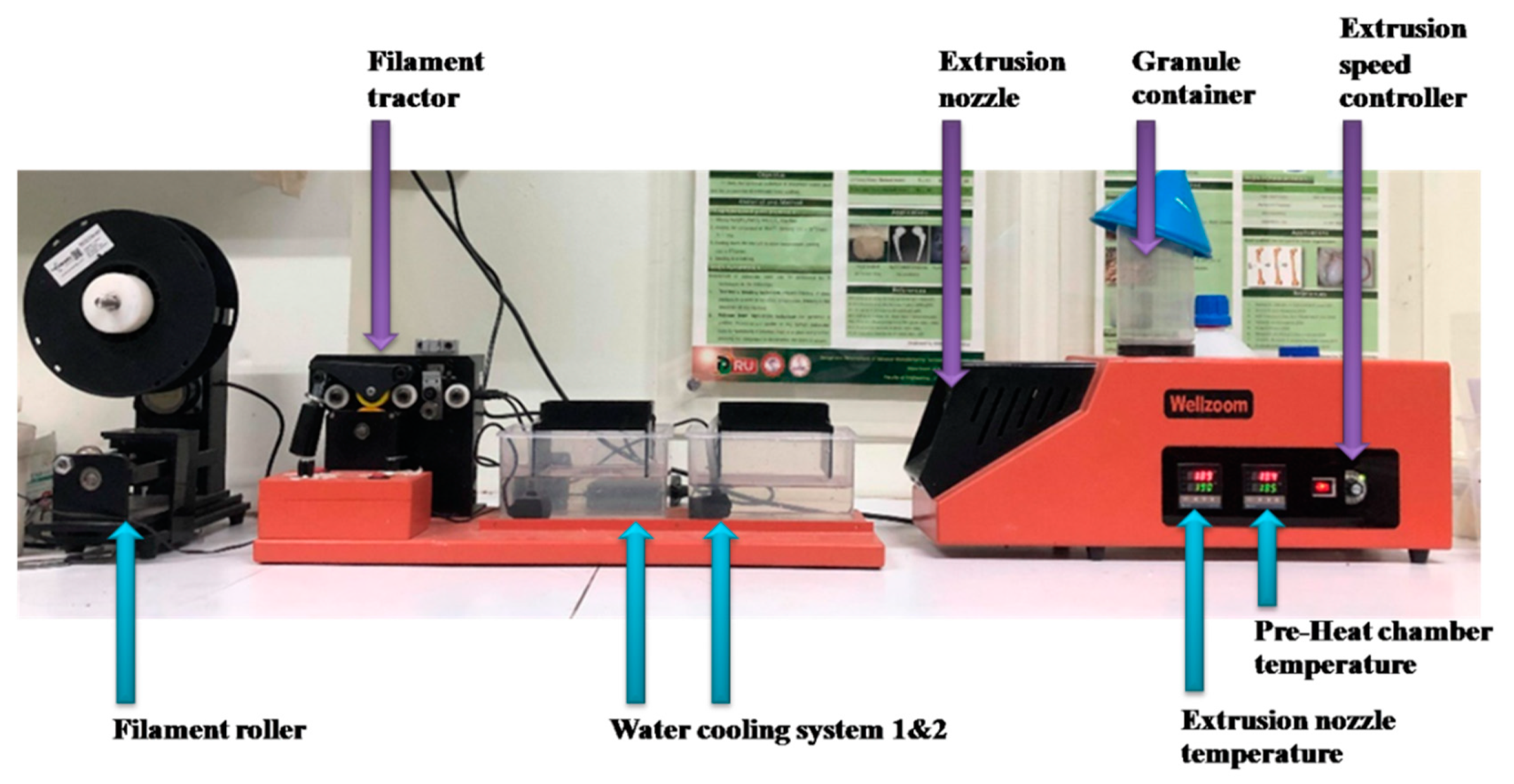
2.3. Filament Extrusion
2.4. Hydroxyapatite and Silk Fibroin Characterization
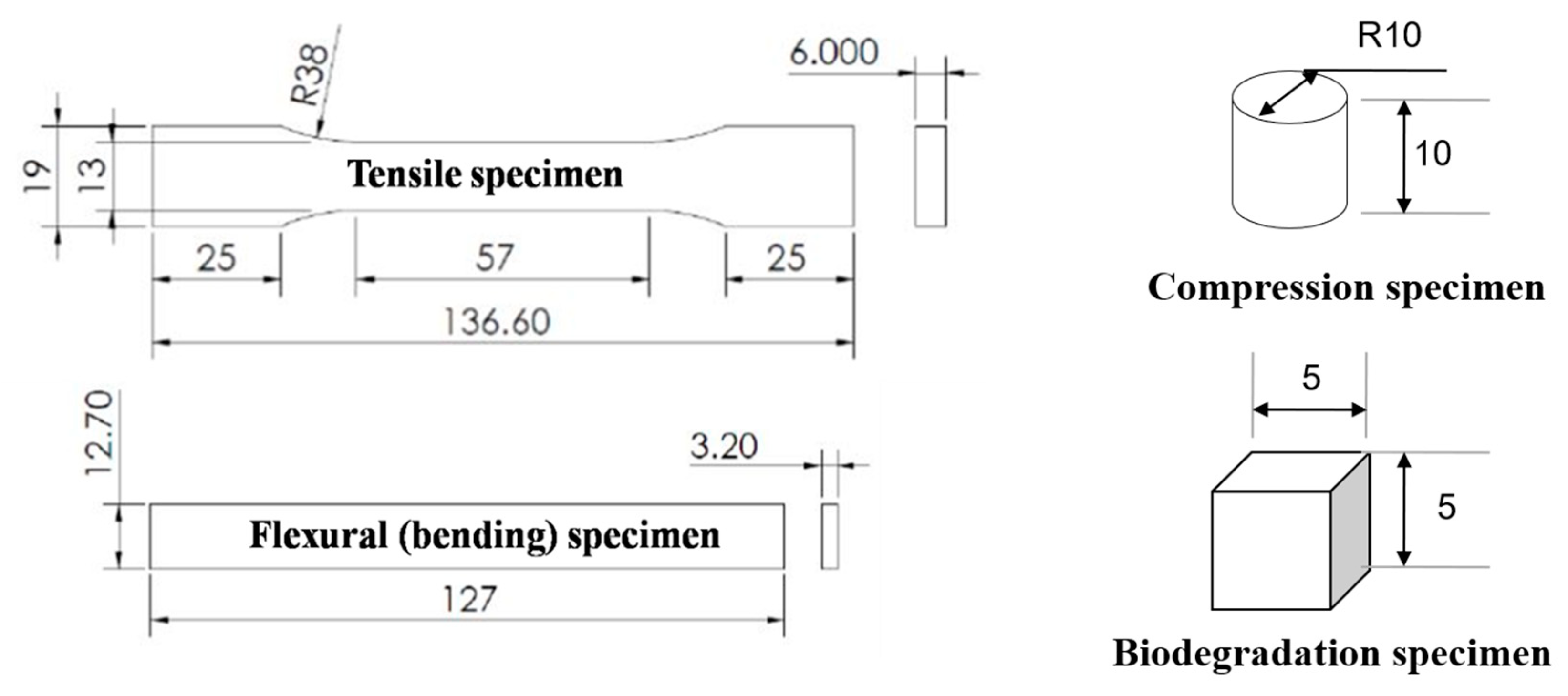
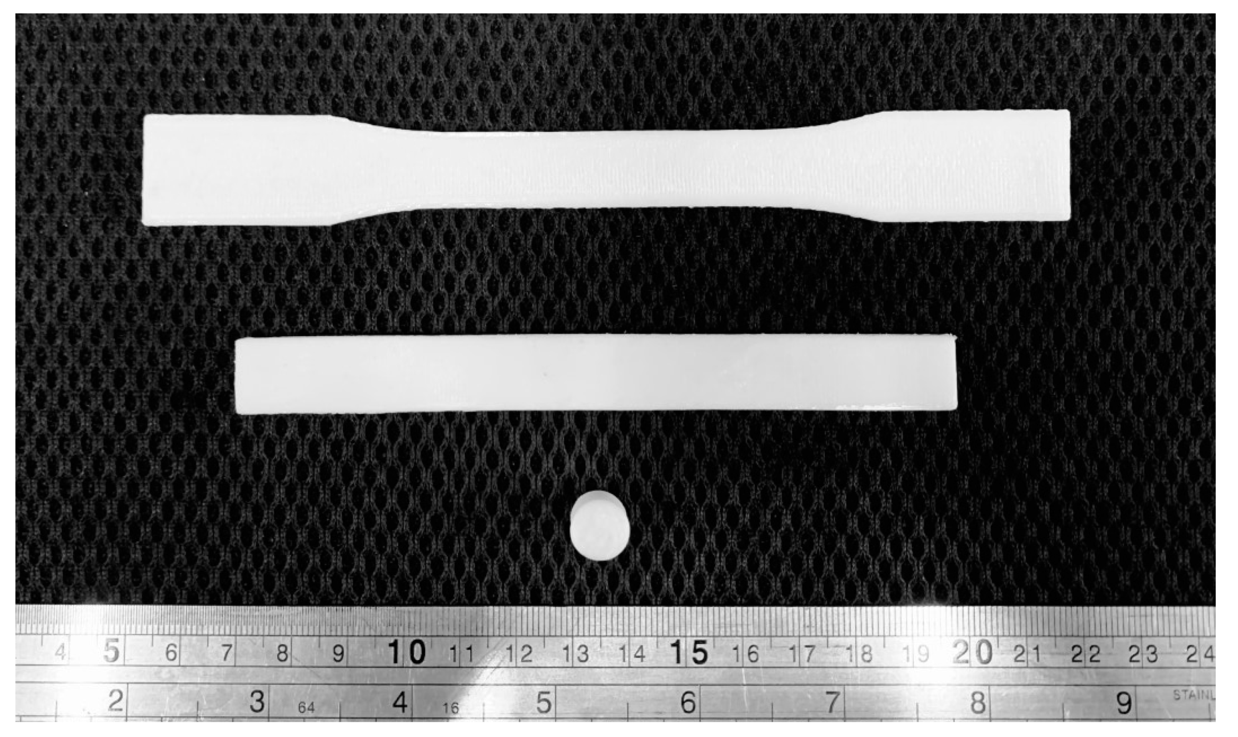
2.5. Mechanical Tests for 3D-Printed Specimen
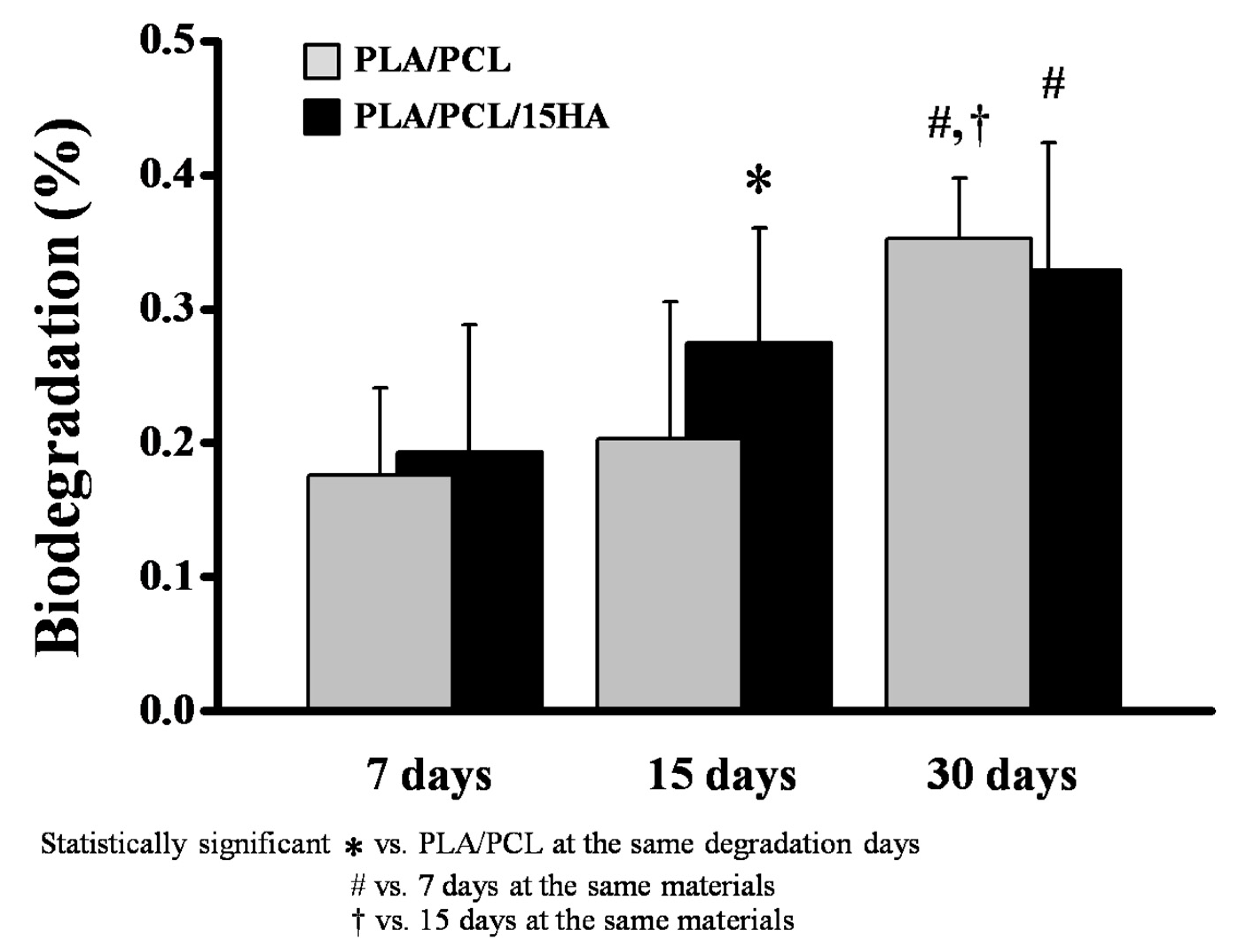
2.6. Biodegradation Test
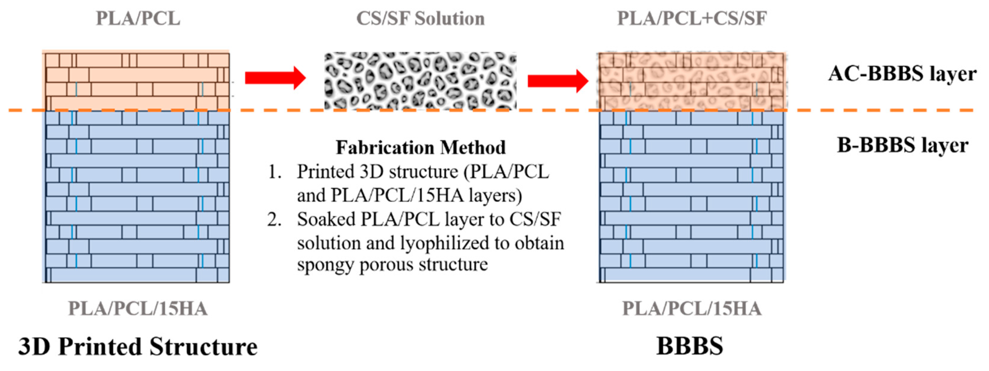
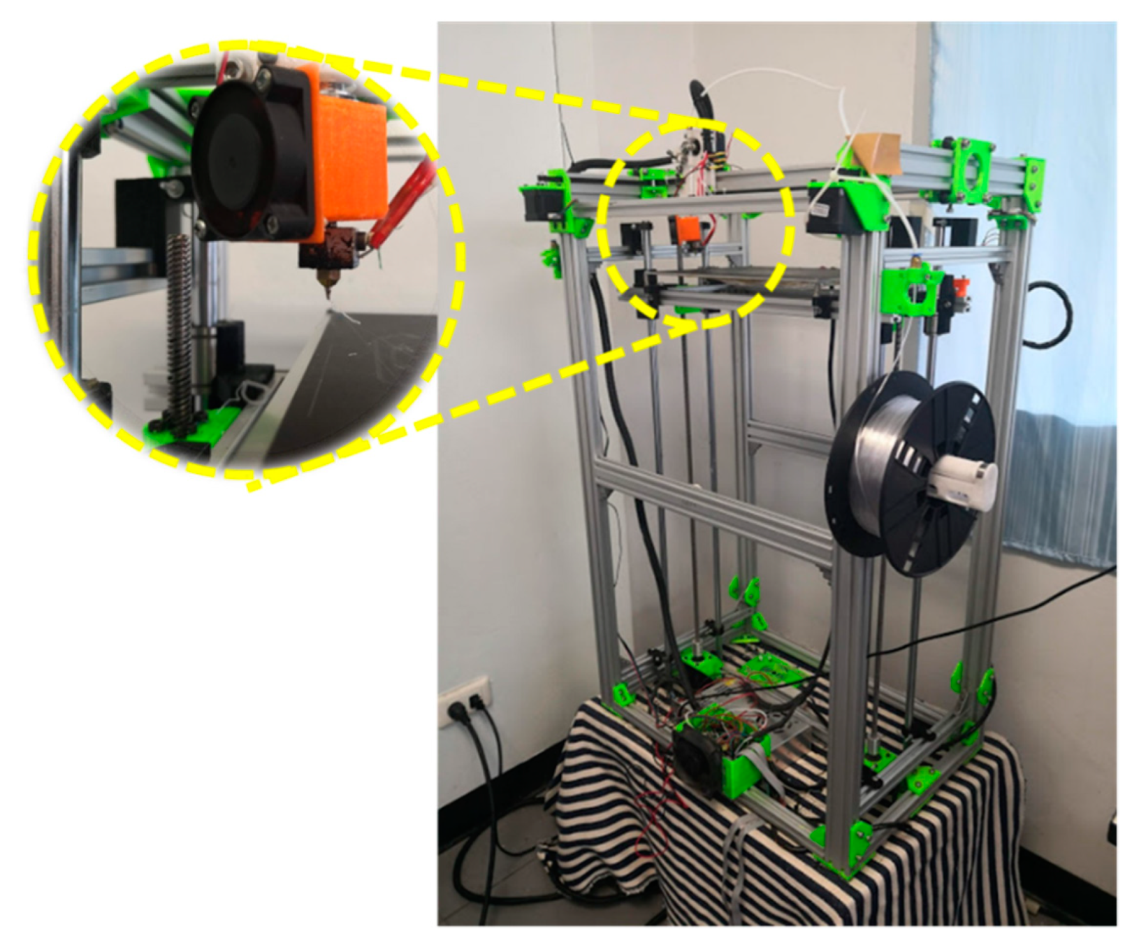
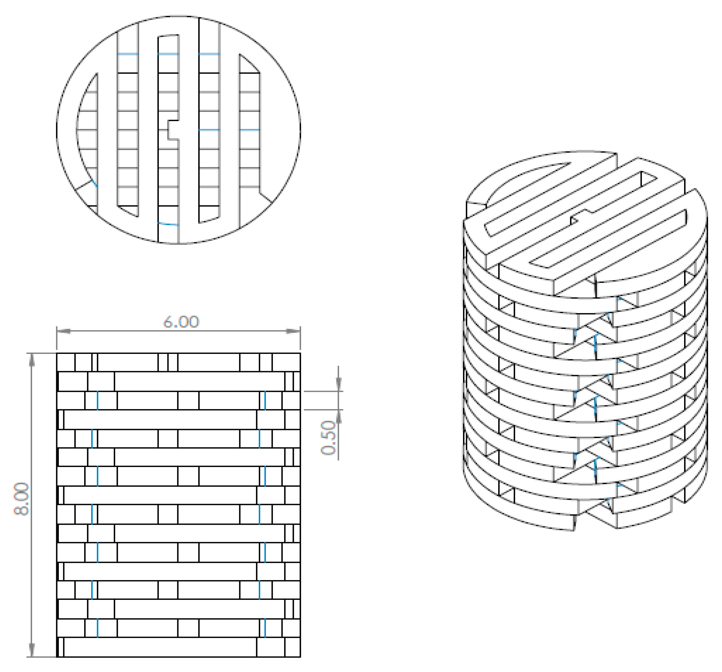
2.7. 3D Printing Conditions and Scaffold Fabrication
2.8. Scanning Electron Microscope (SEM) Observation
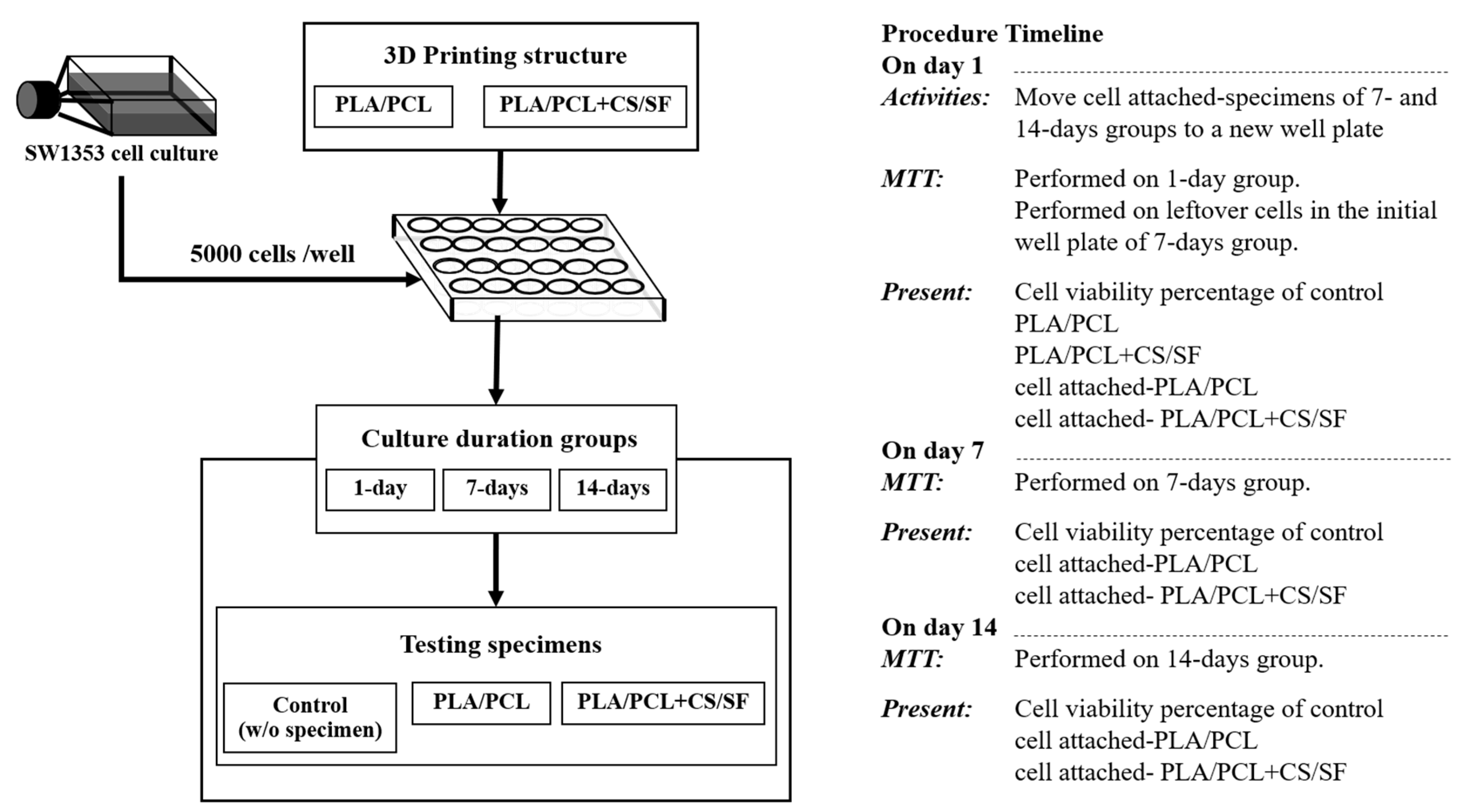
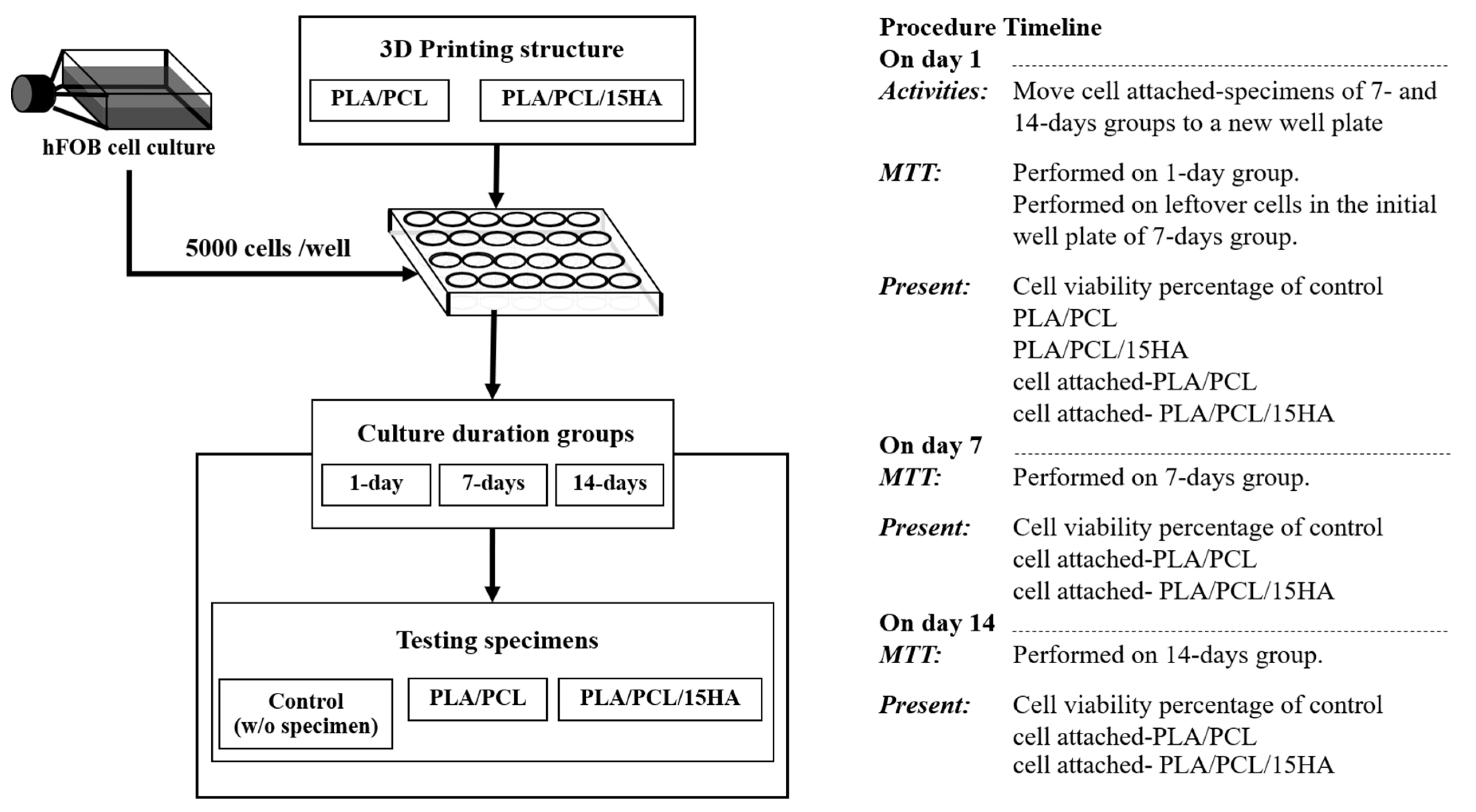
2.9. Cell Culture and Cell Viability Test
2.10. Finite Element Analysis
3. Results
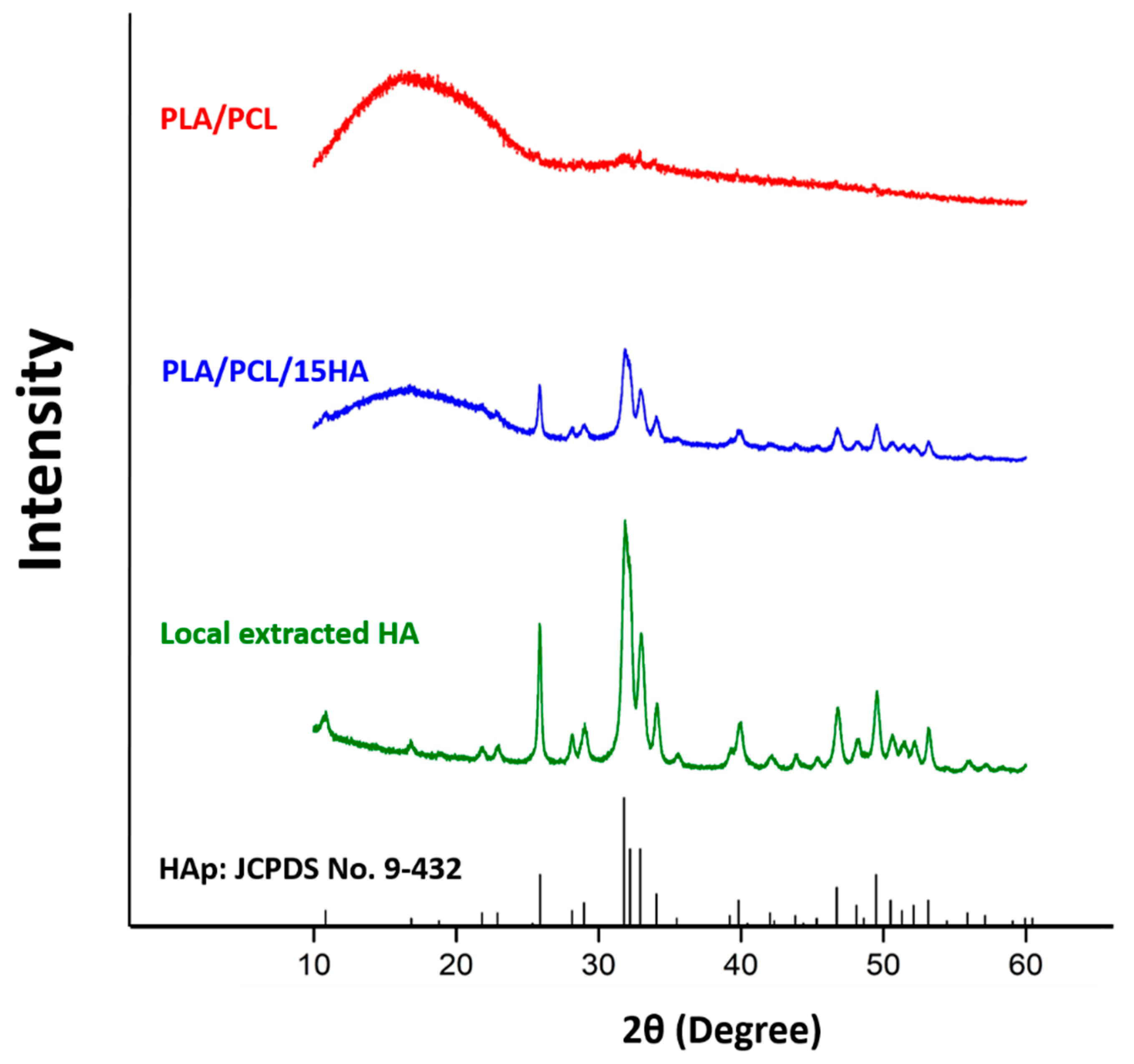
3.1. XRD
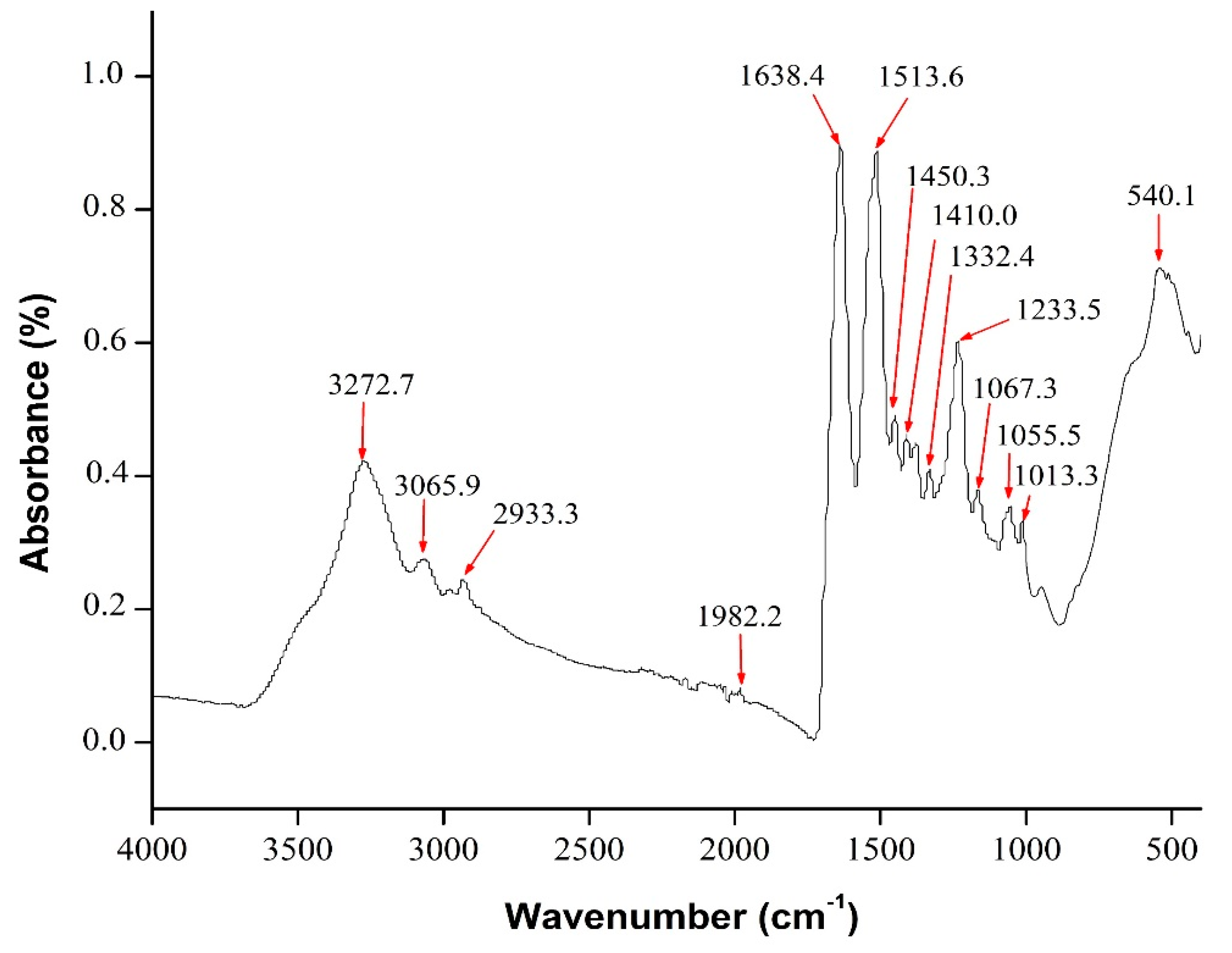
3.2. FTIR
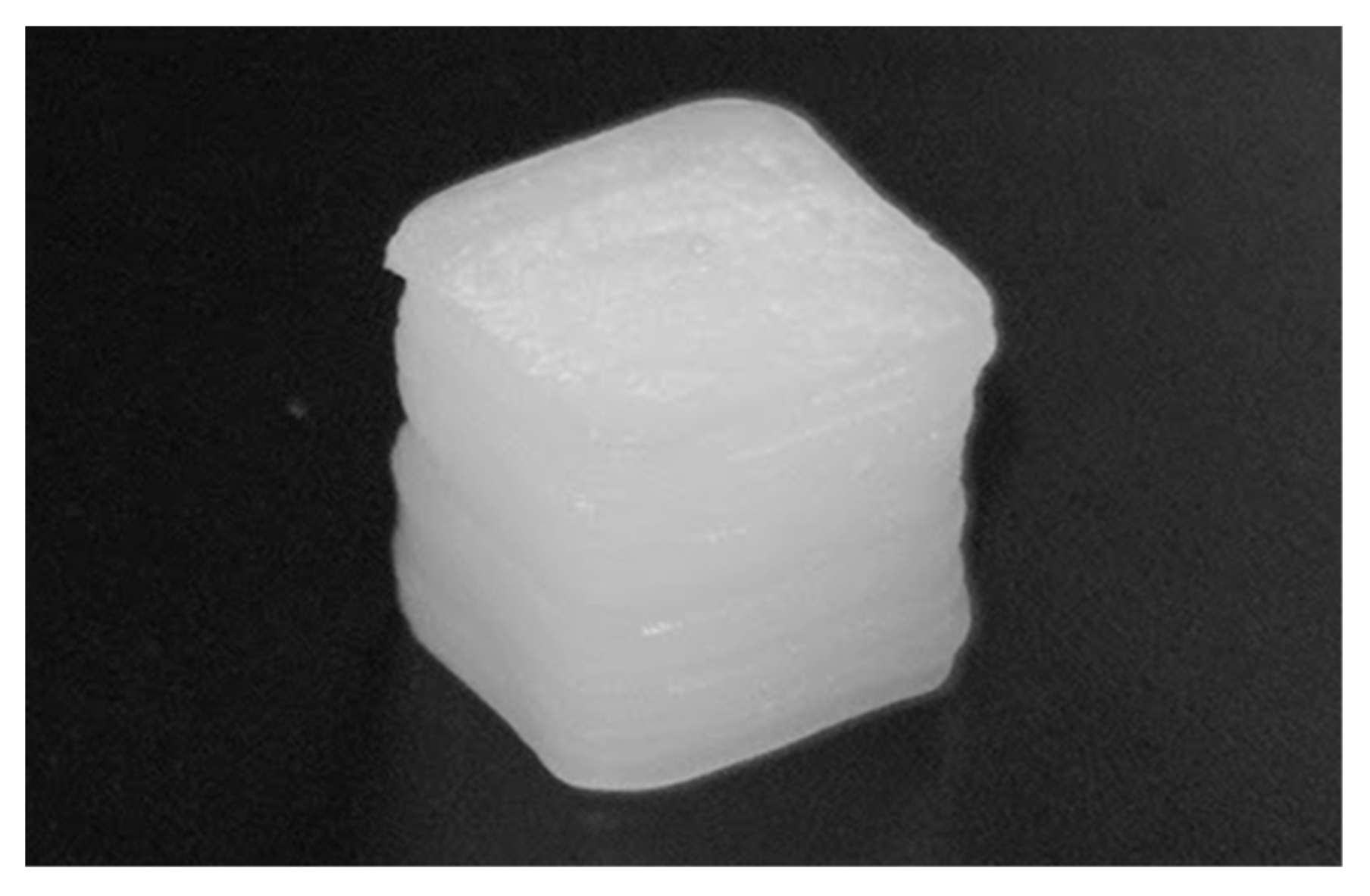
3.3. Compression Test
3.4. Tensile Test
3.5. Flexural (Bending) Test
3.6. Biodegradation Test
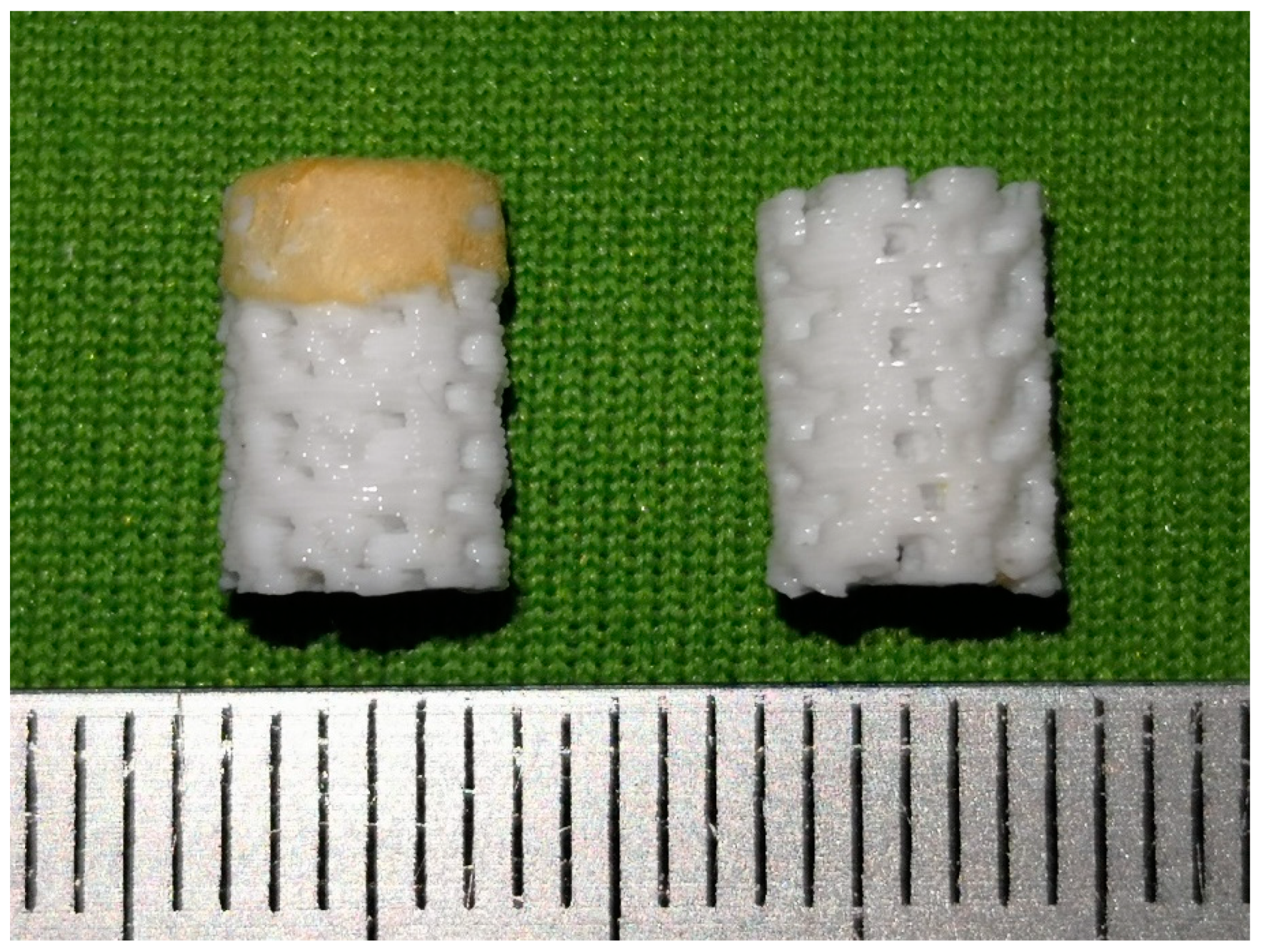
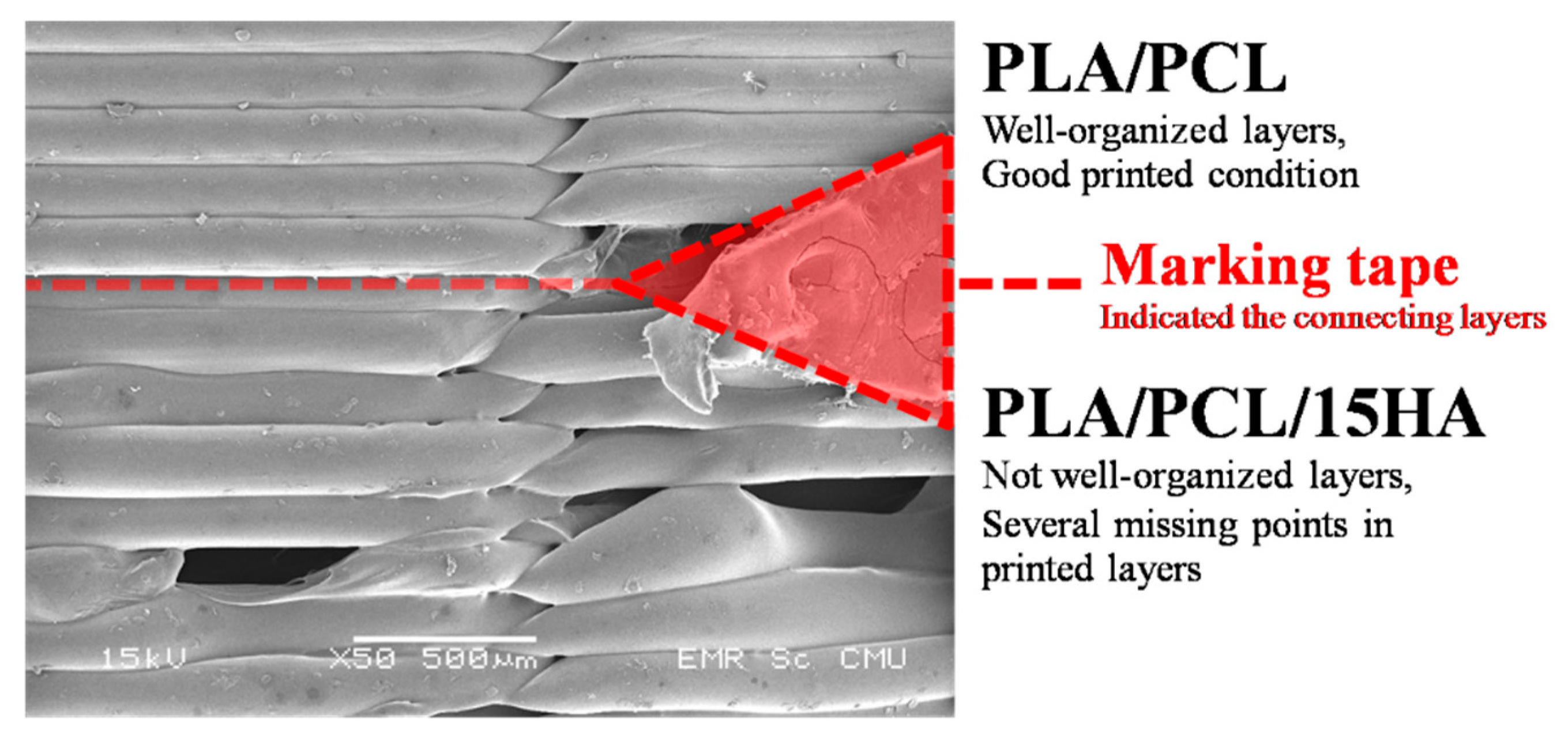
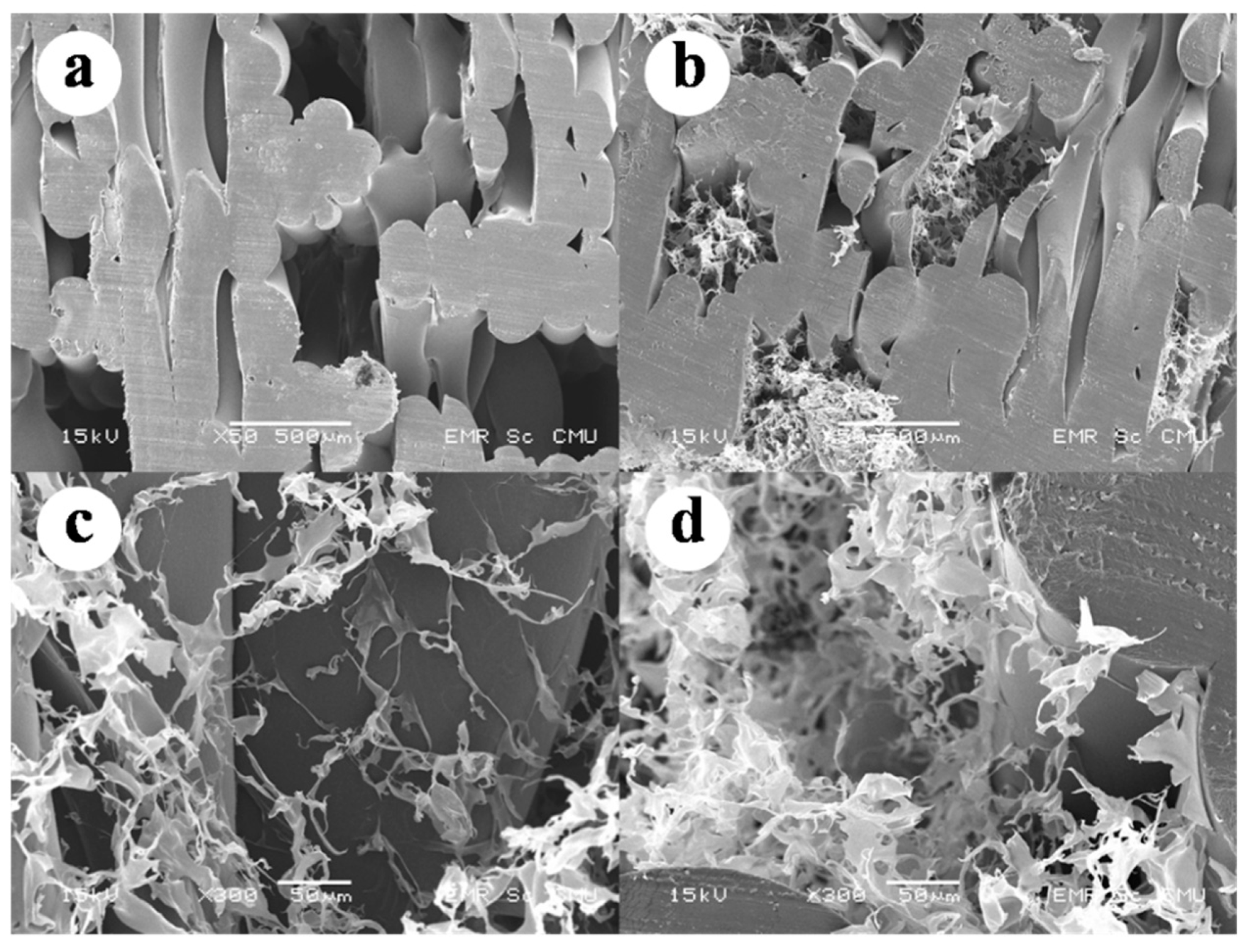
3.7. BBBS Morphology
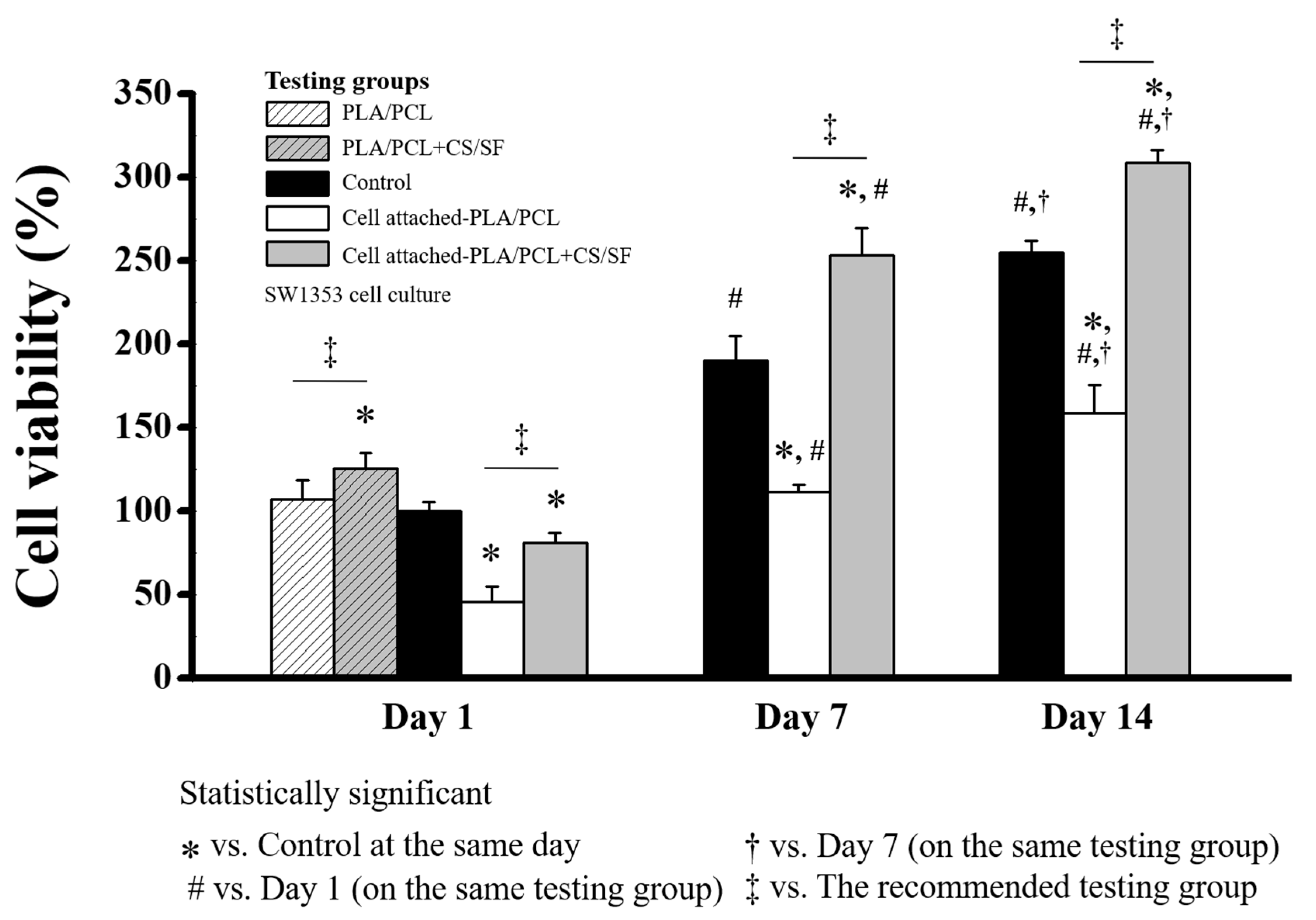
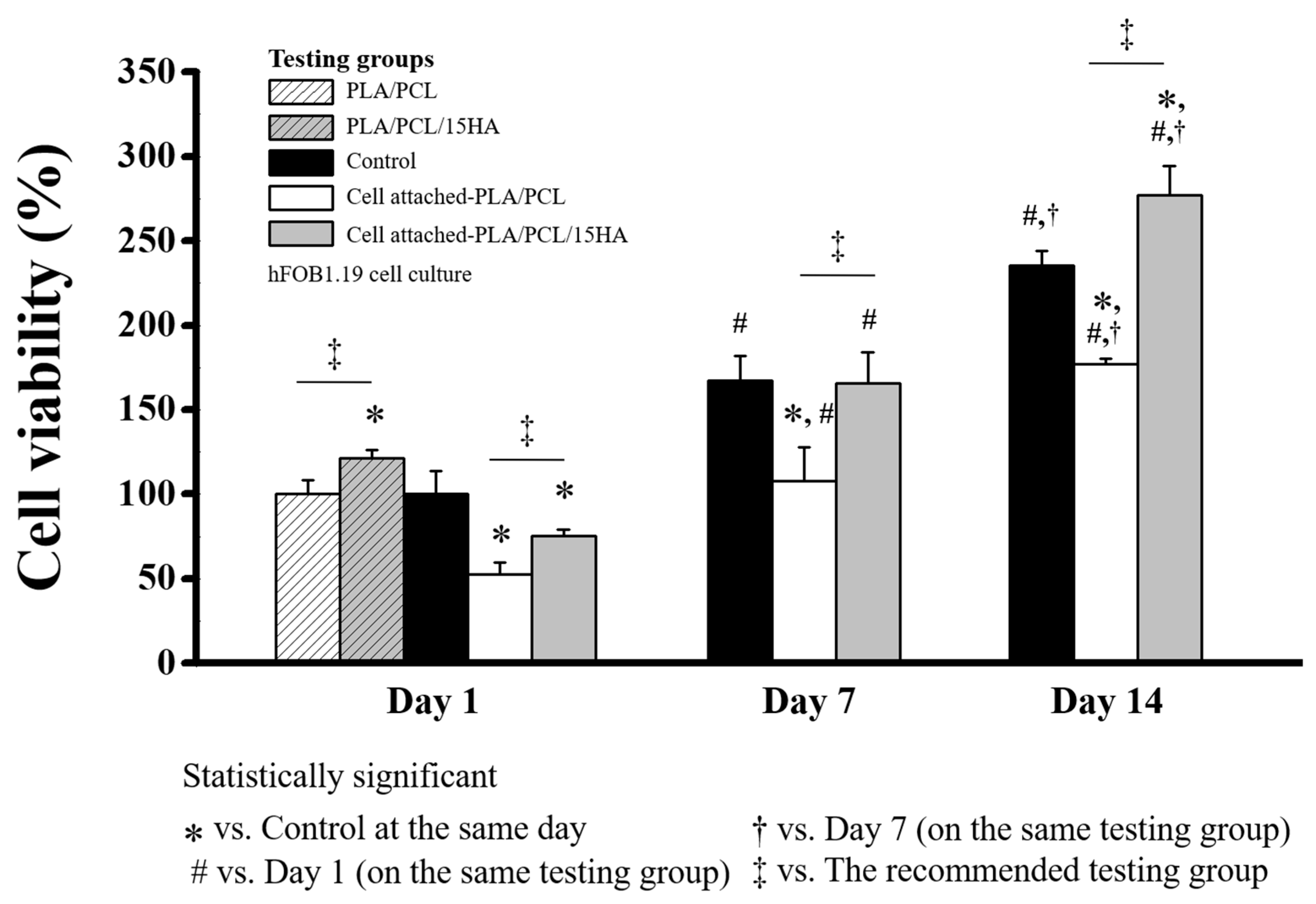
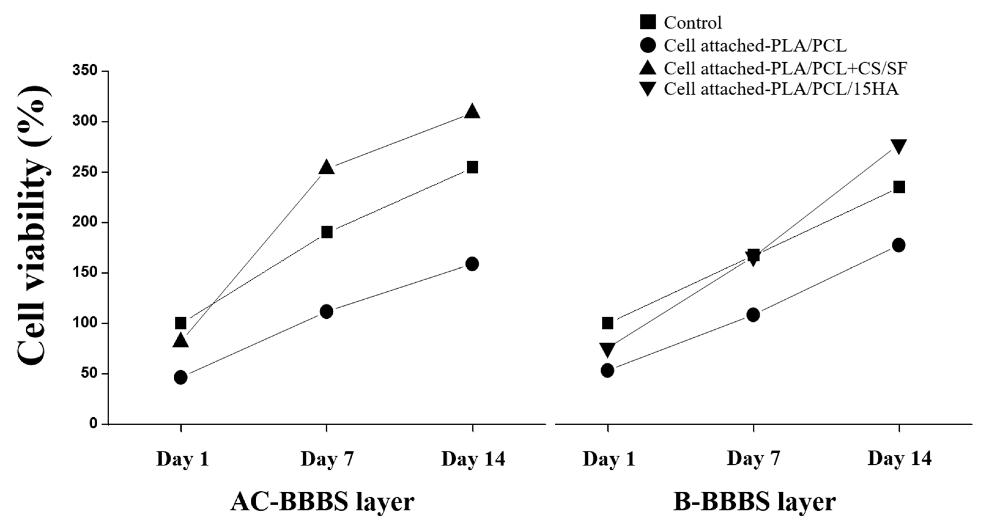
3.8. Cell Viability Test for AC-BBBS
3.9. Cell Viability Test for B-BBBS
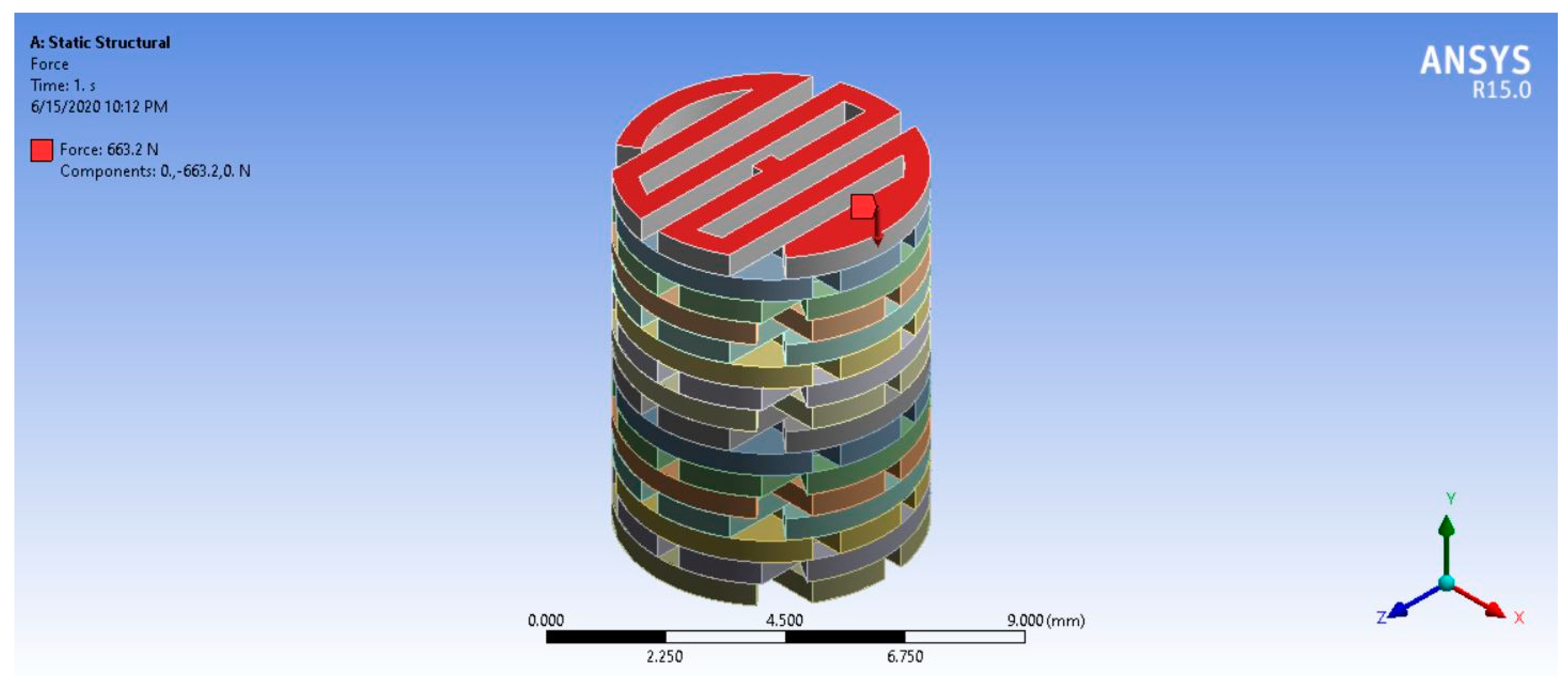
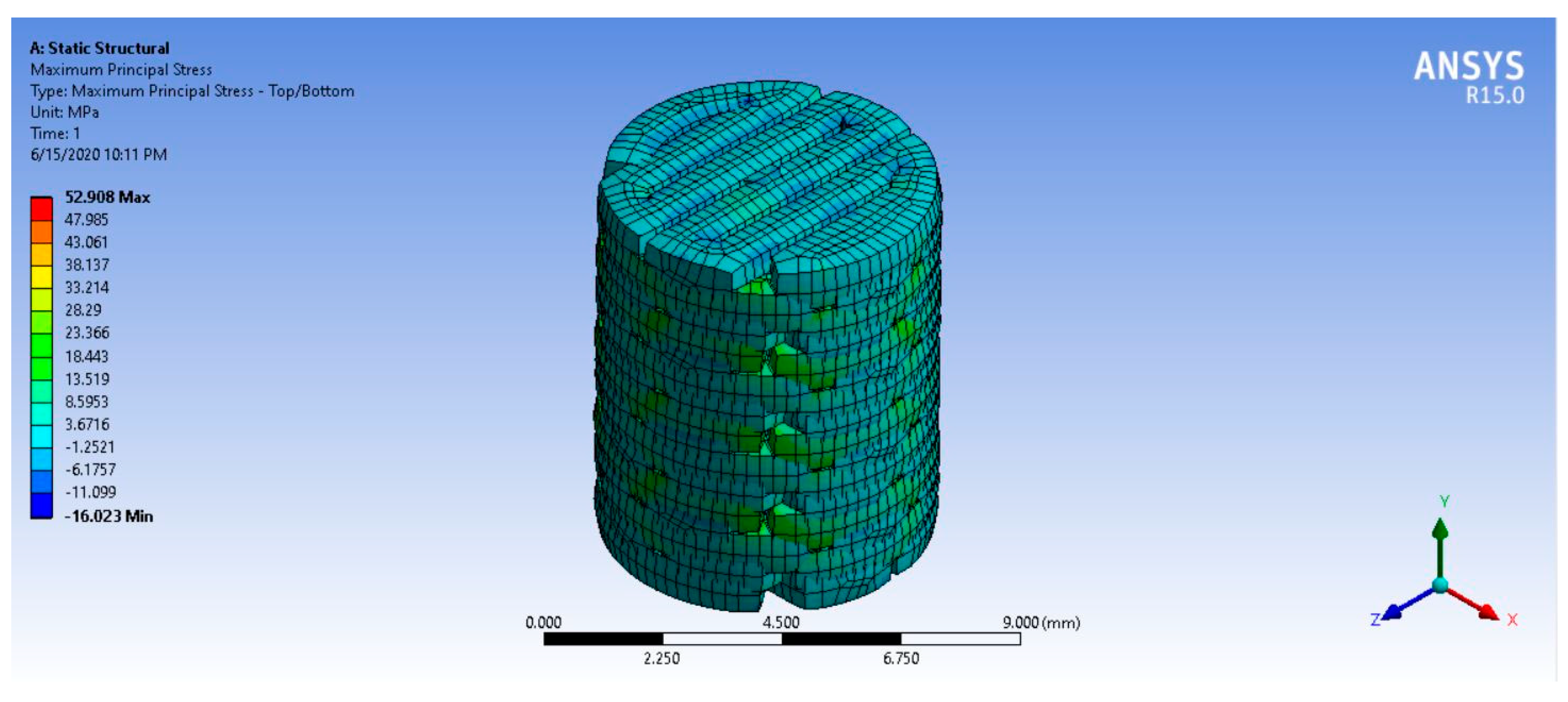
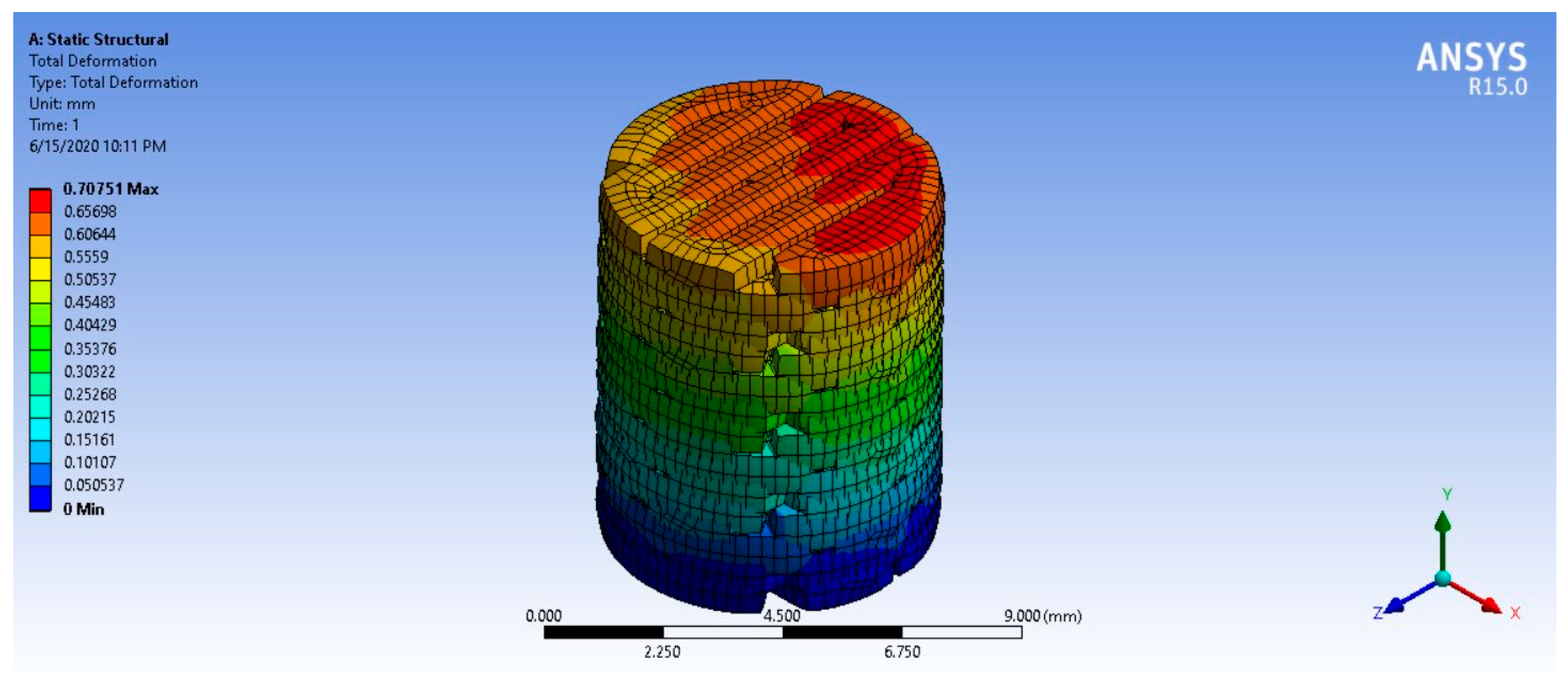
3.10. Finite Element Analysis
4. Discussion
5. Conclusions
Author Contributions
Funding
Acknowledgments
Conflicts of Interest
References
- McCredie, J. Nerves in bone: The silent partners. Skelet. Radiol. 2007, 36, 473–475. [Google Scholar] [CrossRef] [PubMed]
- Madeira, C.; Santhagunam, A.; Salgueiro, J.B.; Cabral, J.M. Advanced cell therapies for articular cartilage regeneration. Trends Biotechnol. 2015, 33, 35–42. [Google Scholar] [CrossRef] [PubMed]
- Mithoefer, K.; Peterson, L.; Zenobi-Wong, M.; Mandelbaum, B.R. Cartilage issues in football-today’s problems and tomorrow’s solutions. Br. J. Sports Med. 2015, 49, 590–596. [Google Scholar] [CrossRef] [PubMed]
- Ishihara, K.; Nakayama, K.; Akieda, S.; Matsuda, S.; Iwamoto, Y. Simultaneous regeneration of full-thickness cartilage and subchondral bone defects in vivo using a three-dimensional scaffold-free autologous construct derived from high-density bone marrow-derived mesenchymal stem cells. J. Orthop. Surg. Res. 2014, 9, 98. [Google Scholar] [CrossRef] [PubMed]
- Brittberg, M.; Lindahl, A.; Nilsson, A.; Ohlsson, C.; Isaksson, O.; Peterson, L. Treatment of deep cartilage defects in the knee with autologous chondrocyte transplantation. N. Engl. J. Med. 1994, 331, 889–895. [Google Scholar] [CrossRef]
- Ozmeric, A.; Alemdaroglu, K.B.; Aydogan, N.H. Treatment for cartilage injuries of the knee with a new treatment algorithm. World J. Orthop. 2014, 5, 677–684. [Google Scholar] [CrossRef]
- ICRS–Articular Cartilage Injury Classification. Available online: http://www.drstorm.dk/Instruks_for_laeger/knae/IKDC/icrs.htm (accessed on 10 October 2016).
- Martinez-Carranza, N.; Ryd, L.; Hultenby, K.; Hedlund, H.; Nurmi-Sandh, H.; Lagerstedt, A.S.; Schupbach, P.; Berg, H.E. Treatment of full thickness focal cartilage lesions with a metallic resurfacing implant in a sheep animal model, 1 year evaluation. Osteoarthr. Cartil. 2015, 24, 484–493. [Google Scholar] [CrossRef]
- Muller, S.; Breederveld, R.S.; Tuinebreijer, W.E. Results of osteochondral autologous transplantation in the knee. Open Orthop. J. 2010, 4, 111–114. [Google Scholar] [CrossRef]
- Seo, S.S.; Kim, C.W.; Jung, D.W. Management of focal chondral lesion in the knee joint. Knee Surg. Relat. Res. 2011, 23, 185–196. [Google Scholar] [CrossRef]
- Cole, A.B.Y.B.J. Cartilage Repair and Replacement: From Osteochondral Autograft Transfer to Allograft. In Arthritis & Arthroplasty: The knee; Brown, T.E., Ed.; Elsevier: Amsterdam, The Netherlands, 2009; p. 9. [Google Scholar]
- Hirano, S.; Tsuchida, H.; Nagao, N. N-acetylation in chitosan and the rate of its enzymic hydrolysis. Biomaterials 1989, 10, 574–576. [Google Scholar] [CrossRef]
- Abdel-Sayed, P.; Pioletti, D.P. Strategies for improving the repair of focal cartilage defects. Nanomedicine 2015, 10, 2893–2905. [Google Scholar] [CrossRef] [PubMed]
- Enea, D.; Cecconi, S.; Calcagno, S.; Busilacchi, A.; Manzotti, S.; Gigante, A. One-step cartilage repair in the knee: Collagen-covered microfracture and autologous bone marrow concentrate. A pilot study. Knee 2015, 22, 30–35. [Google Scholar] [CrossRef] [PubMed]
- Pitjamit, S.; Thunsiri, K.; Nakkiew, W.; Wongwichai, T.; Pothacharoen, P.; Wattanutchariya, W. The Possibility of Interlocking Nail Fabrication from FFF 3D Printing PLA/PCL/HA Composites Coated by Local Silk Fibroin for Canine Bone Fracture Treatment. Materials 2020, 13, 1564. [Google Scholar] [CrossRef] [PubMed]
- Akindoyo, J.O.; Beg, M.D.; Ghazali, S.; Heim, H.P.; Feldmann, M. Impact modified PLA-hydroxyapatite composites–Thermo-mechanical properties. Compos. Part A Appl. Sci. Manuf. 2018, 107, 326–333. [Google Scholar] [CrossRef]
- Nájera, S.E.; Michel, M.; Kim, N.-S. 3D Printed PLA/PCL/TiO2 Composite for Bone Replacement and Grafting. MRS Adv. 2018, 3, 2373–2378. [Google Scholar] [CrossRef]
- Petinakis, E.; Yu, L.; Edward, G.; Dean, K.; Liu, H.; Scully, A.D. Effect of matrix–particle interfacial adhesion on the mechanical properties of poly (lactic acid)/wood-flour micro-composites. J. Polym. Environ. 2009, 17, 83. [Google Scholar] [CrossRef]
- Ziaee, F.; Zebarjad, S.M.; Javadpour, S. Compressive and flexural properties of novel polylactic acid/hydroxyapatite/yttria-stabilized zirconia hybrid nanocomposite scaffold. Int. J. Polym. Mater. Polym. Biomater. 2018, 67, 229–238. [Google Scholar] [CrossRef]
- Auras, R.A.; Lim, L.T.; Selke, S.E.M.; Tsuji, H. Poly (lactic acid): Synthesis, Structures, Properties, Processing, and Applications; John Wiley & Sons, Inc.: Hoboken, NJ, USA, 2011. [Google Scholar]
- Pandele, A.M.; Constantinescu, A.; Radu, I.C.; Miculescu, F.; Ioan Voicu, S.; Ciocan, L.T. Synthesis and Characterization of PLA-Micro-structured Hydroxyapatite Composite Films. Materials 2020, 13, 274. [Google Scholar] [CrossRef]
- Zhou, Z.; Yi, Q.; Liu, X.; Liu, L.; Liu, Q. In vitro degradation behaviors of poly-L-lactide/bioactive glass composite materials in phosphate-buffered solution. Polym. Bull. 2009, 63, 575–586. [Google Scholar] [CrossRef]
- Vink, E.T.; Rabago, K.R.; Glassner, D.A.; Gruber, P.R. Applications of life cycle assessment to NatureWorks™ polylactide (PLA) production. Polym. Degrad. Stab. 2003, 80, 403–419. [Google Scholar] [CrossRef]
- Lasprilla, A.J.; Martinez, G.A.; Lunelli, B.H.; Jardini, A.L.; Maciel Filho, R. Poly-lactic acid synthesis for application in biomedical devices—A review. Biotechnol. Adv. 2012, 30, 321–328. [Google Scholar] [CrossRef] [PubMed]
- Maitz, M.F. Applications of synthetic polymers in clinical medicine. Biosurf. Biotribol. 2015, 1, 161–176. [Google Scholar] [CrossRef]
- Pandey, A.K. Recent advancements of biodegradable polylactic acid/polylactide: A review on synthesis, characterization and applications. Adv. Matter Lett. 2014, 1–56. [Google Scholar] [CrossRef]
- Weng, Y.-X.; Jin, Y.-J.; Meng, Q.-Y.; Wang, L.; Zhang, M.; Wang, Y.-Z. Biodegradation behavior of poly (butylene adipate-co-terephthalate) (PBAT), poly (lactic acid) (PLA), and their blend under soil conditions. Polym. Test. 2013, 32, 918–926. [Google Scholar] [CrossRef]
- Mohapatra, A.K.; Mohanty, S.; Nayak, S. Effect of PEG on PLA/PEG blend and its nanocomposites: A study of thermo-mechanical and morphological characterization. Polym. Compos. 2014, 35, 283–293. [Google Scholar] [CrossRef]
- Cheng, Z.; Teoh, S.-H. Surface modification of ultra thin poly (ε-caprolactone) films using acrylic acid and collagen. Biomaterials 2004, 25, 1991–2001. [Google Scholar] [CrossRef]
- Kim, M.S.; Kim, G. Three-dimensional electrospun polycaprolactone (PCL)/alginate hybrid composite scaffolds. Carbohydr. Polym. 2014, 114, 213–221. [Google Scholar] [CrossRef]
- Williams, J.M.; Adewunmi, A.; Schek, R.M.; Flanagan, C.L.; Krebsbach, P.H.; Feinberg, S.E.; Hollister, S.J.; Das, S. Bone tissue engineering using polycaprolactone scaffolds fabricated via selective laser sintering. Biomaterials 2005, 26, 4817–4827. [Google Scholar] [CrossRef]
- Lin, W.-J.; Flanagan, D.R.; Linhardt, R.J. A novel fabrication of poly (ε-caprolactone) microspheres from blends of poly (ε-caprolactone) and poly (ethylene glycol) s. Polymer 1999, 40, 1731–1735. [Google Scholar] [CrossRef]
- Lanza, R.; Langer, R.; Vacanti, J.P. Principles of Tissue Engineering; Academic Press: Cambridge, MA, USA, 2011. [Google Scholar]
- Hsu, C.-M. Electrospinning of Poly (£-Caprolactone). Master’s Thesis, Worcester Polytechnic Institute, Worcester, MA, USA, May 2003. [Google Scholar]
- Middleton, J.C.; Tipton, A.J. Synthetic biodegradable polymers as orthopedic devices. Biomaterials 2000, 21, 2335–2346. [Google Scholar] [CrossRef]
- Jones, D.S.; Djokic, J.; McCoy, C.P.; Gorman, S.P. Poly (ε-caprolactone) and poly (ε-caprolactone)-polyvinylpyrrolidone-iodine blends as ureteral biomaterials: Characterisation of mechanical and surface properties, degradation and resistance to encrustation in vitro. Biomaterials 2002, 23, 4449–4458. [Google Scholar] [CrossRef]
- Dhanaraju, M.D.; Jayakumar, R.; Vamsadhara, C. Influence of manufacturing parameters on development of contraceptive steroid loaded injectable microspheres. Chem. Pharm. Bull. 2004, 52, 976–979. [Google Scholar] [CrossRef] [PubMed]
- Dong, L.; Wang, S.-J.; Zhao, X.-R.; Zhu, Y.-F.; Yu, J.-K. 3D-printed poly (ε-caprolactone) scaffold integrated with cell-laden chitosan hydrogels for bone tissue engineering. Sci. Rep. 2017, 7, 1–9. [Google Scholar] [CrossRef] [PubMed]
- Kim, Y.B.; Kim, G.H. PCL/alginate composite scaffolds for hard tissue engineering: Fabrication, characterization, and cellular activities. ACS Comb. Sci. 2015, 17, 87–99. [Google Scholar] [CrossRef]
- Huang, A.; Jiang, Y.; Napiwocki, B.; Mi, H.; Peng, X.; Turng, L.-S. Fabrication of poly (ε-caprolactone) tissue engineering scaffolds with fibrillated and interconnected pores utilizing microcellular injection molding and polymer leaching. RSC Adv. 2017, 7, 43432–43444. [Google Scholar] [CrossRef]
- Hasan, A.; Soliman, S.; El Hajj, F.; Tseng, Y.-T.; Yalcin, H.C.; Marei, H.E. Fabrication and in vitro characterization of a tissue engineered PCL-PLLA heart valve. Sci. Rep. 2018, 8, 1–13. [Google Scholar] [CrossRef]
- Dash, T.K.; Konkimalla, V.B. Polymeric modification and its implication in drug delivery: Poly-ε-caprolactone (PCL) as a model polymer. Mol. Pharm. 2012, 9, 2365–2379. [Google Scholar] [CrossRef]
- Rai, A.; Senapati, S.; Saraf, S.K.; Maiti, P. Biodegradable poly (ε-caprolactone) as a controlled drug delivery vehicle of vancomycin for the treatment of MRSA infection. J. Mater. Chem. B 2016, 4, 5151–5160. [Google Scholar] [CrossRef]
- Grossen, P.; Witzigmann, D.; Sieber, S.; Huwyler, J. PEG-PCL-based nanomedicines: A biodegradable drug delivery system and its application. J. Controll. Release 2017, 260, 46–60. [Google Scholar] [CrossRef]
- Chang, S.H.; Lee, H.J.; Park, S.; Kim, Y.; Jeong, B. Fast degradable polycaprolactone for drug delivery. Biomacromolecules 2018, 19, 2302–2307. [Google Scholar] [CrossRef]
- Sarasam, A.; Madihally, S.V. Characterization of chitosan–polycaprolactone blends for tissue engineering applications. Biomaterials 2005, 26, 5500–5508. [Google Scholar] [CrossRef] [PubMed]
- Navarro-Baena, I.; Sessini, V.; Dominici, F.; Torre, L.; Kenny, J.M.; Peponi, L. Design of biodegradable blends based on PLA and PCL: From morphological, thermal and mechanical studies to shape memory behavior. Polym. Degrad. Stab. 2016, 132, 97–108. [Google Scholar] [CrossRef]
- García Cruz, D.M.; Gomez Ribelles, J.L.; Salmerón Sánchez, M. Blending polysaccharides with biodegradable polymers. I. Properties of chitosan/polycaprolactone blends. J. Biomed. Mater. Res. Part B Appl. Biomater. Off. J. Soc. Biomater. Jpn. Soc. Biomater. Aust. Soc. Biomater. Korean Soc. Biomater. 2008, 85, 303–313. [Google Scholar]
- Narayanan, G.; Gupta, B.S.; Tonelli, A.E. Poly (ε-caprolactone) Nanowebs Functionalized with α-and γ-Cyclodextrins. Biomacromolecules 2014, 15, 4122–4133. [Google Scholar] [CrossRef] [PubMed]
- Jing, Q.; Law, J.Y.; Tan, L.P.; Silberschmidt, V.V.; Li, L.; Dong, Z. Preparation, characterization and properties of polycaprolactone diol-functionalized multi-walled carbon nanotube/thermoplastic polyurethane composite. Compos. Part A Appl. Sci. Manuf. 2015, 70, 8–15. [Google Scholar] [CrossRef]
- Kang, N.H.; Kim, S.J.; Song, S.H.; Choi, S.; Choi, S.Y.; Kim, Y.J. Hydroxyapatite synthesis using EDTA. J. Craniofac Surg. 2013, 24, 1042–1045. [Google Scholar] [CrossRef]
- Barakat, N.A.M.; Khil, M.S.; Omran, A.M.; Sheikh, F.A.; Kim, H.Y. Extraction of pure natural hydroxyapatite from the bovine bones bio waste by three different methods. J. Mater. Process. Technol. 2009, 209, 3408–3415. [Google Scholar] [CrossRef]
- Liang, W.R.; Rahaman, M.N.; Day, D.E.; Marion, N.W.; Riley, C.; Mao, J.J. Bioactive borate glass scaffold for bone tissue engineering. J. Non Cryst. Solids 2008, 354, 1690–1696. [Google Scholar] [CrossRef]
- Sivakumar, M.; Kumar, T.S.; Shantha, K.L.; Rao, K.P. Development of hydroxyapatite derived from Indian coral. Biomaterials 1996, 17, 1709–1714. [Google Scholar] [CrossRef]
- Abu Bakar, M.S.; Cheng, M.H.; Tang, S.M.; Yu, S.C.; Liao, K.; Tan, C.T.; Khor, K.A.; Cheang, P. Tensile properties, tension-tension fatigue and biological response of polyetheretherketone-hydroxyapatite composites for load-bearing orthopedic implants. Biomaterials 2003, 24, 2245–2250. [Google Scholar] [CrossRef]
- Melville, J.C.; Shum, J.W.; Young, S.; Wong, M.E. Regenerative Strategies for Maxillary and Mandibular Reconstruction: A Practical Guide; Springer Nature Switzerland AG: Basel, Switzerland, 2019. [Google Scholar]
- Thunsiri, K.; Udomsom, S.; Wattanutchariya, W. Characteristic of Pore Structure and Cells Growth on the Various Ratio of Silk Fibroin and Hydroxyapatite in Chitosan Base Scaffold. Key Eng. Mater. 2016, 675, 459–462. [Google Scholar] [CrossRef]
- Wattanutchariya, W.; Thunsiri, K. Effects of Fibroin Treatments on Physical and Biological Properties of Chitosan/Hydroxyapatite/Fibroin Bone’s Scaffold. Appl. Mech. Mater. 2015, 799, 488–492. [Google Scholar] [CrossRef]
- Lu, J.X.; Prudhommeaux, F.; Meunier, A.; Sedel, L.; Guillemin, G. Effects of chitosan on rat knee cartilages. Biomaterials 1999, 20, 1937–1944. [Google Scholar]
- Madihally, S.V.; Matthew, H.W. Porous chitosan scaffolds for tissue engineering. Biomaterials 1999, 20, 1133–1142. [Google Scholar] [CrossRef]
- Cuero, R.G. Antimicrobial action of exogenous chitosan. EXS 1999, 87, 315–333. [Google Scholar]
- Felt, O.; Carrel, A.; Baehni, P.; Buri, P.; Gurny, R. Chitosan as tear substitute: A wetting agent endowed with antimicrobial efficacy. J. Ocul. Pharmacol. Ther. 2000, 16, 261–270. [Google Scholar] [CrossRef]
- Tsai, G.J.; Su, W.H. Antibacterial activity of shrimp chitosan against Escherichia coli. J. Food Prot. 1999, 62, 239–243. [Google Scholar] [CrossRef]
- Tanase, C.E.; Popa, M.I.; Verestiuc, L. Biomimetic bone scaffolds based on chitosan and calcium phosphates. Mater. Lett. 2011, 65, 1681–1683. [Google Scholar] [CrossRef]
- Mondal, M.; Trivedy, K.; Kumar, S.N.; Kumar, V.; Bandlamori, S.V. Scanning Electron Microscopic Study on The Cocoon Filaments and Degummed Fibers of Two Silkmoth Hybrids of Bombyx Mori Linn. Int. J. Innov. Res. Dev. 2013, 5, 2956–2965. [Google Scholar]
- Yang, M.; Shuai, Y.; He, W.; Min, S.; Zhu, L. Preparation of porous scaffolds from silk fibroin extracted from the silk gland of Bombyx mori (B. mori). Int. J. Mol. Sci. 2012, 13, 7762–7775. [Google Scholar] [CrossRef]
- Murphy, A.R.; Kaplan, D.L. Biomedical applications of chemically-modified silk fibroin. J. Mater. Chem. 2009, 19, 6443–6450. [Google Scholar] [CrossRef]
- Wenk, E.; Merkle, H.P.; Meinel, L. Silk fibroin as a vehicle for drug delivery applications. J. Controll. Release 2011, 150, 128–141. [Google Scholar] [CrossRef]
- Yan, L.P.; Oliveira, J.M.; Oliveira, A.L.; Caridade, S.G.; Mano, J.F.; Reis, R.L. Macro/microporous silk fibroin scaffolds with potential for articular cartilage and meniscus tissue engineering applications. Acta Biomater. 2012, 8, 289–301. [Google Scholar] [CrossRef]
- Arunrat, K.; Santi, M.; Sineenat, S. Fibroin Protein Extraction from Red Ant Nests for a production of ElectrospunNanofibers. Asia Pac. J. Sci. Technol. 2010, 15, 919–929. [Google Scholar]
- Ding, X.; Zhu, M.; Xu, B.; Zhang, J.; Zhao, Y.; Ji, S.; Wang, L.; Li, X.; Kong, D.; Ma, X.; et al. Integrated trilayered silk fibroin scaffold for osteochondral differentiation of adipose-derived stem cells. ACS Appl. Mater. Interfaces 2014, 6, 16696–16705. [Google Scholar] [CrossRef]
- Pitjamit, S.; Sriprapha, P.; Nakkiew, W. Suitable forming condition of hydroxyapatite and bioactive glass composites for a bone fixation plate using Taguchi experimental design. Eng. Appl. Sci. Res. 2016, 43, 466–469. [Google Scholar]
- Felfel, R.M.; Poocza, L.; Gimeno-Fabra, M.; Milde, T.; Hildebrand, G.; Ahmed, I.; Scotchford, C.; Sottile, V.; Grant, D.M.; Liefeith, K. In vitro degradation and mechanical properties of PLA-PCL copolymer unit cell scaffolds generated by two-photon polymerization. Biomed. Mater. 2016, 11, 015011. [Google Scholar] [CrossRef]
- Gilbert, M. Brydson’s Plastics Materials; Elsevier: Amsterdam, The Netherlands, 2016. [Google Scholar]
- Yao, Q.; Cosme, J.G.; Xu, T.; Miszuk, J.M.; Picciani, P.H.; Fong, H.; Sun, H. Three dimensional electrospun PCL/PLA blend nanofibrous scaffolds with significantly improved stem cells osteogenic differentiation and cranial bone formation. Biomaterials 2017, 115, 115–127. [Google Scholar] [CrossRef]
- Gurarslan, A.; Shen, J.; Tonelli, A.E. Behavior of poly (ε-caprolactone) s (PCLs) coalesced from their stoichiometric urea inclusion compounds and their use as nucleants for crystallizing PCL melts: Dependence on PCL molecular weights. Macromolecules 2012, 45, 2835–2840. [Google Scholar] [CrossRef]
- Phengchan, P.; Chaijaruwanich, A.; Nakkiew, W.; Pitjamit, S. Characterization and fabrication of bio-composite filaments for fused deposition modeling 3D printing. IOP Conf. Ser. Mater. Sci. Eng. 2019, 639, 012019. [Google Scholar] [CrossRef]
- Tao, Y.; Wang, H.; Li, Z.; Li, P.; Shi, S.Q. Development and application of wood flour-filled polylactic acid composite filament for 3D printing. Materials 2017, 10, 339. [Google Scholar] [CrossRef] [PubMed]
- Esposito Corcione, C.; Gervaso, F.; Scalera, F.; Montagna, F.; Sannino, A.; Maffezzoli, A. The feasibility of printing polylactic acid–nanohydroxyapatite composites using a low-cost fused deposition modeling 3D printer. J. Appl. Polym. Sci. 2017, 134. [Google Scholar] [CrossRef]
- Marra, K.G.; Szem, J.W.; Kumta, P.N.; DiMilla, P.A.; Weiss, L.E. In vitro analysis of biodegradable polymer blend/hydroxyapatite composites for bone tissue engineering. J. Biomed. Mater. Res. Off. J. Soc. Biomater. Jpn. Soc. Biomater. Aust. Soc. Biomater. Korean Soc. Biomater. 1999, 47, 324–335. [Google Scholar] [CrossRef]
- Nilsson, S.; Santesson, S. Chromatography. In ENZYMES; Wilson, I.D., Ed.; Elsevier: Amsterdam, The Netherlands, 2000. [Google Scholar]
- Hankiewicz, J.; Swierczek, E. Lysozyme in human body fluids. Clin. Chim. Acta 1974, 57, 205–209. [Google Scholar] [CrossRef]
- Porstmann, B.; Jung, K.; Schmechta, H.; Evers, U.; Pergande, M.; Porstmann, T.; Kramm, H.-J.; Krause, H. Measurement of lysozyme in human body fluids: Comparison of various enzyme immunoassay techniques and their diagnostic application. Clin. Biochem. 1989, 22, 349–355. [Google Scholar] [CrossRef]
- Pitjamit, S.; Thunsiri, K.; Nakkiew, W.; Pothacharoen, P. Preparation and characterization of silk fibroin from four different species of Thai-local silk cocoon for Bone implanted applications. IOP Conf. Ser. Mater. Sci. Eng. 2019, 635, 012001. [Google Scholar] [CrossRef]
- Shepherd, D.; Seedhom, B. Thickness of human articular cartilage in joints of the lower limb. Ann. Rheum. Dis. 1999, 58, 27–34. [Google Scholar] [CrossRef]
- Kamalha, E.; Zheng, Y.S.; Zeng, Y.C.; Fredrick, M.N. FTIR and WAXD Study of Regenerated Silk Fibroin. In Advanced Materials Research; Trans Tech Publication: Stafa-Zurich, Switzerland, 2013. [Google Scholar]
- Ruksudjarit, A.; Pengpat, K.; Rujijanagul, G.; Tunkasiri, T. Synthesis and characterization of nanocrystalline hydroxyapatite from natural bovine bone. Curr. Appl. Phys. 2008, 8, 270–272. [Google Scholar] [CrossRef]
- Yetmez, M.; Erkmen, Z.; Kalkandelen, C.; Ficai, A.; Oktar, F. Sintering effects of mullite-doping on mechanical properties of bovine hydroxyapatite. Mater. Sci. Eng. C 2017, 77, 470–475. [Google Scholar] [CrossRef]
- Di Martino, A.; Sittinger, M.; Risbud, M.V. Chitosan: A versatile biopolymer for orthopaedic tissue-engineering. Biomaterials 2005, 26, 5983–5990. [Google Scholar] [CrossRef]
- Costa-Pinto, A.R.; Reis, R.L.; Neves, N.M. Scaffolds based bone tissue engineering: The role of chitosan. Tissue Eng. Part B Rev. 2011, 17, 331–347. [Google Scholar] [CrossRef] [PubMed]
- Nettles, D.L.; Elder, S.H.; Gilbert, J.A. Potential use of chitosan as a cell scaffold material for cartilage tissue engineering. Tissue Eng. 2002, 8, 1009–1016. [Google Scholar] [CrossRef] [PubMed]
- Huang, Y.; Seitz, D.; König, F.; Müller, P.E.; Jansson, V.; Klar, R.M. Induction of Articular Chondrogenesis by Chitosan/Hyaluronic-Acid-Based Biomimetic Matrices Using Human Adipose-Derived Stem Cells. Int. J. Mol. Sci. 2019, 20, 4487. [Google Scholar] [CrossRef] [PubMed]
- Thunsiri, K.; Oonjai, A.; Wattanutchariya, W. Characterization of Hydroxyapatite/ Silk Fibroin/ Chitosan Scaffold for Cartilage Tissue Engineering. Key Eng. Mater. 2018, 775, 120–126. [Google Scholar] [CrossRef]
- Adali, T.; Kalkan, R.; Karimizarandi, L. The chondrocyte cell proliferation of a chitosan/silk fibroin/egg shell membrane hydrogels. Int. J. Biol. Macromol. 2019, 124, 541–547. [Google Scholar] [CrossRef]
- Chomchalao, P.; Pongcharoen, S.; Sutheerawattananonda, M.; Tiyaboonchai, W. Fibroin and fibroin blended three-dimensional scaffolds for rat chondrocyte culture. Biomed. Eng. Online 2013, 12, 28. [Google Scholar] [CrossRef]
- Chen, C.-H.; Liu, J.M.-J.; Chua, C.-K.; Chou, S.-M.; Shyu, V.B.-H.; Chen, J.-P. Cartilage tissue engineering with silk fibroin scaffolds fabricated by indirect additive manufacturing technology. Materials 2014, 7, 2104–2119. [Google Scholar] [CrossRef]
- Zhang, X.; Chang, W.; Lee, P.; Wang, Y.; Yang, M.; Li, J.; Kumbar, S.G.; Yu, X. Polymer-ceramic spiral structured scaffolds for bone tissue engineering: Effect of hydroxyapatite composition on human fetal osteoblasts. PLoS ONE 2014, 9, e85871. [Google Scholar] [CrossRef]
- Ohno, M.; Kimoto, K.; Toyoda, T.; Kawata, K.; Arakawa, H. Fluoride-treated bio-resorbable synthetic nonceramic [corrected] hydroxyapatite promotes proliferation and differentiation of human osteoblastic MG-63 cells. J. Oral Implantol. 2013, 39, 154–160. [Google Scholar] [CrossRef]
- Klangjorhor, J.; Phitak, T.; Pruksakorn, D.; Pothacharoen, P.; Kongtawelert, P. Comparison of growth factor adsorbed scaffold and conventional scaffold with growth factor supplemented media for primary human articular chondrocyte 3D culture. BMC Biotechnol. 2014, 14, 108. [Google Scholar] [CrossRef]
- Klein, J. Chemistry. Repair or replacement-A joint perspective. Science 2009, 323, 47–48. [Google Scholar] [PubMed]
- Lin, W.; Mashiah, R.; Seror, J.; Kadar, A.; Dolkart, O.; Pritsch, T.; Goldberg, R.; Klein, J. Lipid-hyaluronan synergy strongly reduces intrasynovial tissue boundary friction. Acta Biomater. 2019, 83, 314–321. [Google Scholar] [CrossRef] [PubMed]
- Jahn, S.; Seror, J.; Klein, J. Lubrication of Articular Cartilage. Annu. Rev. Biomed. Eng. 2016, 18, 235–258. [Google Scholar] [CrossRef] [PubMed]
- Liu, J.; Kerns, D.G. Mechanisms of guided bone regeneration: A review. Open Dent. J. 2014, 8, 56–65. [Google Scholar] [CrossRef] [PubMed]
- Wang, H.; Gee, A.O.; Hutchinson, I.D.; Stoner, K.; Warren, R.F.; Chen, T.O.; Maher, S.A. Bone Plug Versus Suture-Only Fixation of Meniscal Grafts: Effect on Joint Contact Mechanics During Simulated Gait. Am. J. Sports Med. 2014, 42, 1682–1689. [Google Scholar] [CrossRef]


| 2θ: HAp (JCPDS 9-432) | Plane | 2θ: HA (Local Extracted) | ||
|---|---|---|---|---|
| h | k | l | ||
| 21.82 | 2 | 0 | 0 | 21.85 |
| 22.902 | 1 | 1 | 1 | 22.99 |
| 25.354 | 2 | 0 | 1 | 25.47 |
| 25.879 | 0 | 0 | 2 | 25.86 |
| 28.127 | 1 | 0 | 2 | 28.14 |
| 28.967 | 2 | 1 | 0 | 28.97 |
| 31.774 | 2 | 1 | 1 | 31.86 |
| 32.197 | 1 | 1 | 2 | 32.2 |
| 32.902 | 3 | 0 | 0 | 32.97 |
| 34.049 | 2 | 0 | 2 | 34.09 |
| 35.481 | 3 | 0 | 1 | 35.49 |
| 39.205 | 2 | 1 | 2 | 39.27 |
| 39.819 | 3 | 1 | 0 | 39.99 |
| 42.03 | 3 | 1 | 1 | 42.09 |
| 43.805 | 1 | 1 | 3 | 43.8 |
| 45.306 | 2 | 0 | 3 | 45.3 |
| 46.713 | 2 | 2 | 2 | 46.75 |
| 48.104 | 3 | 1 | 2 | 48.14 |
| 48.624 | 3 | 2 | 0 | 48.68 |
| 49.469 | 2 | 1 | 3 | 49.54 |
| Conformation | Amides and Wavenumbers (cm−1) | ||
|---|---|---|---|
| I (CO Stretch) | II (NH Deformation) | III (CN Stretch, NH Bends) | |
| β-sheet | 1625–1640 | 1520–1530 | 1219–1245 |
| Random coil | 1625–1660 | 1520–1545 | 1257–1258 |
| Specimen Compositions | Mechanical Properties | Mean | SD |
|---|---|---|---|
| PLA/PCL | Ultimate Strain (%) | 9.97 | 1.07 |
| Ultimate Stress (MPa) | 77.92 | 2.40 | |
| Modulus of Elasticity (GPa) | 1.01 | 0.04 | |
| PLA/PCL/15HA | Ultimate Strain (%) | 10.68 | 1.43 |
| Ultimate Stress (MPa) | 83.19* | 1.63 | |
| Modulus of Elasticity (GPa) | 1.07 | 0.16 |
| Specimen Compositions | Mechanical Properties | Mean | SD |
|---|---|---|---|
| PLA/PCL | Elongation at Break (%) | 5.73 | 1.01 |
| Ultimate Stress (MPa) | 64.29 | 3.64 | |
| Modulus of Elasticity (GPa) | 1.10 | 0.03 | |
| PLA/PCL/15HA | Elongation at Break (%) | 5.58 | 0.45 |
| Ultimate Stress (MPa) | 52.91* | 1.73 | |
| Modulus of Elasticity (GPa) | 0.97 | 0.11 |
| Specimen Compositions | Mechanical Properties | Mean | SD |
|---|---|---|---|
| PLA/PCL | Ultimate Strain (%) | 11.94 | 1.10 |
| Ultimate Stress (MPa) | 104.02 | 2.12 | |
| Modulus of Elasticity (GPa) | 2.24 | 0.21 | |
| PLA/PCL/15HA | Ultimate Strain (%) | 11.22 | 1.69 |
| Ultimate Stress (MPa) | 102.77 | 3.82 | |
| Modulus of Elasticity (GPa) | 2.41 | 0.40 |
© 2020 by the authors. Licensee MDPI, Basel, Switzerland. This article is an open access article distributed under the terms and conditions of the Creative Commons Attribution (CC BY) license (http://creativecommons.org/licenses/by/4.0/).
Share and Cite
Thunsiri, K.; Pitjamit, S.; Pothacharoen, P.; Pruksakorn, D.; Nakkiew, W.; Wattanutchariya, W. The 3D-Printed Bilayer’s Bioactive-Biomaterials Scaffold for Full-Thickness Articular Cartilage Defects Treatment. Materials 2020, 13, 3417. https://doi.org/10.3390/ma13153417
Thunsiri K, Pitjamit S, Pothacharoen P, Pruksakorn D, Nakkiew W, Wattanutchariya W. The 3D-Printed Bilayer’s Bioactive-Biomaterials Scaffold for Full-Thickness Articular Cartilage Defects Treatment. Materials. 2020; 13(15):3417. https://doi.org/10.3390/ma13153417
Chicago/Turabian StyleThunsiri, Kittiya, Siwasit Pitjamit, Peraphan Pothacharoen, Dumnoensun Pruksakorn, Wasawat Nakkiew, and Wassanai Wattanutchariya. 2020. "The 3D-Printed Bilayer’s Bioactive-Biomaterials Scaffold for Full-Thickness Articular Cartilage Defects Treatment" Materials 13, no. 15: 3417. https://doi.org/10.3390/ma13153417
APA StyleThunsiri, K., Pitjamit, S., Pothacharoen, P., Pruksakorn, D., Nakkiew, W., & Wattanutchariya, W. (2020). The 3D-Printed Bilayer’s Bioactive-Biomaterials Scaffold for Full-Thickness Articular Cartilage Defects Treatment. Materials, 13(15), 3417. https://doi.org/10.3390/ma13153417