Fabrication of Micro Ultrasonic Powder Molding Polypropylene Part with Hydrophobic Patterned Surface


Abstract
1. Introduction
2. Experimental
2.1. Materials
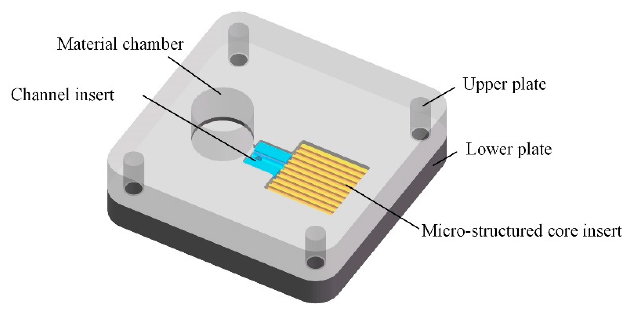
2.2. Mold Design
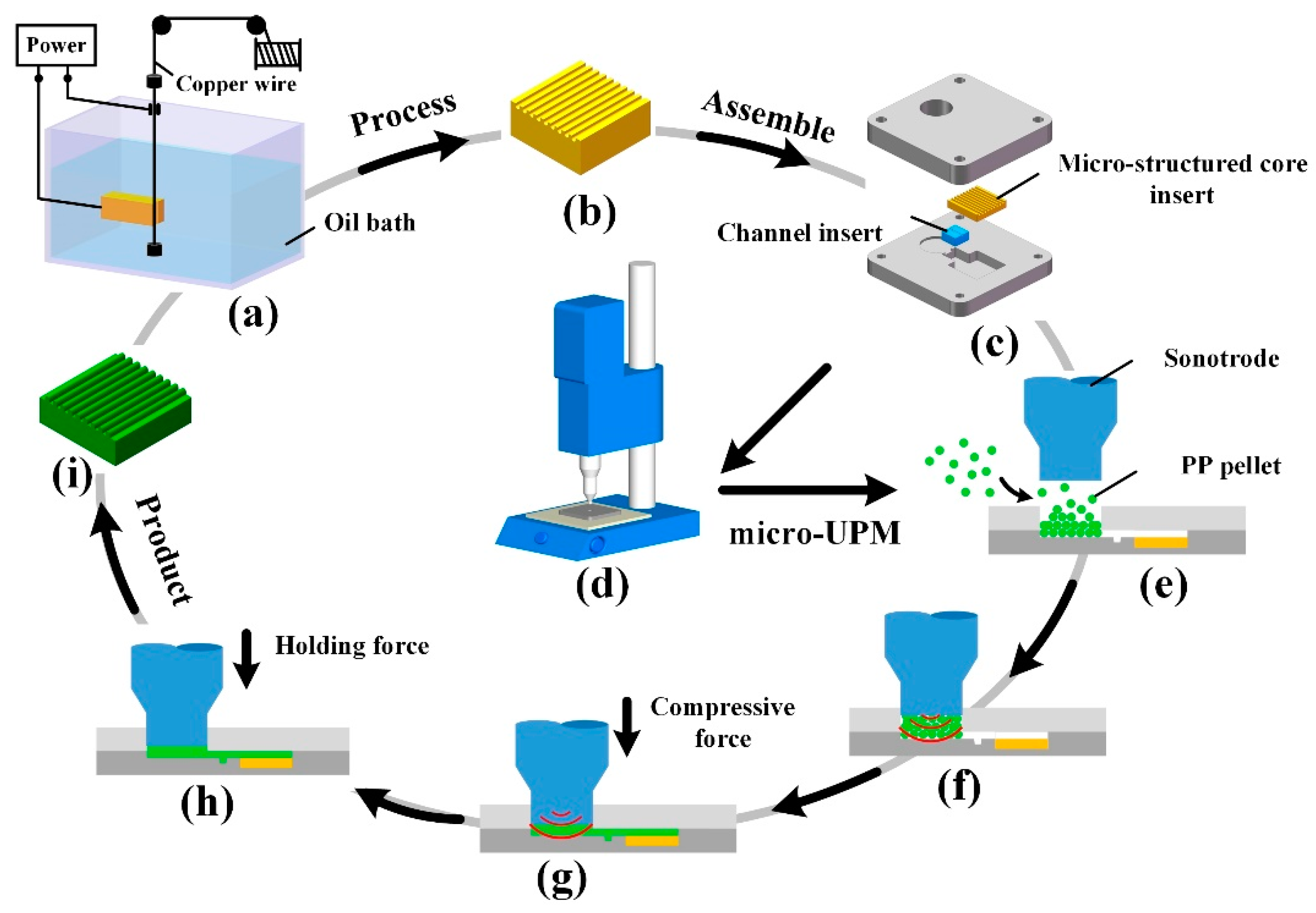
2.3. Ultrasonic Molding Equipment and Processing Flow
2.4. Experimental Method
2.5. Measurement
3. Results and Discussion
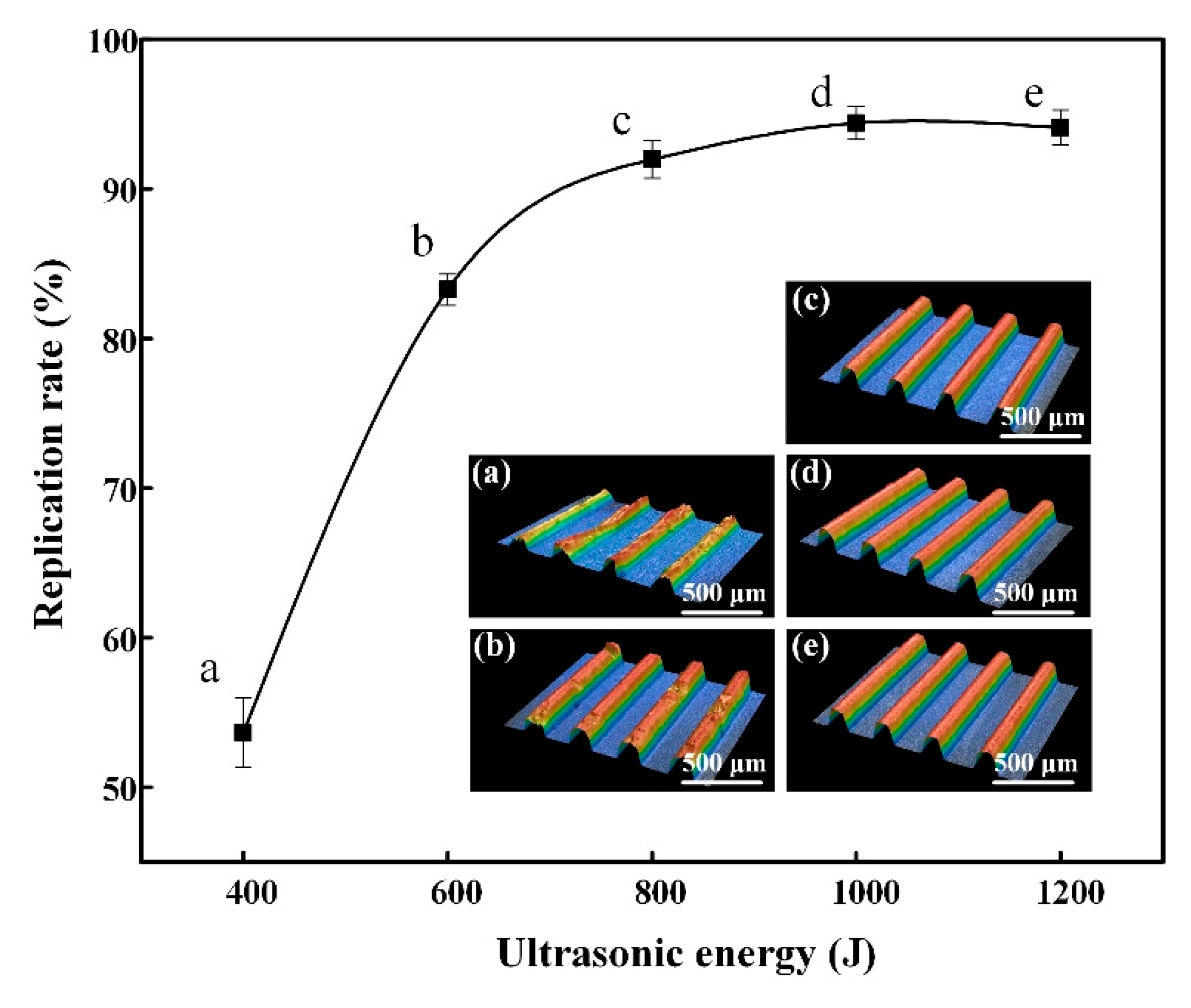
3.1. Effect of Ultrasonic Energy on the Molding Quality
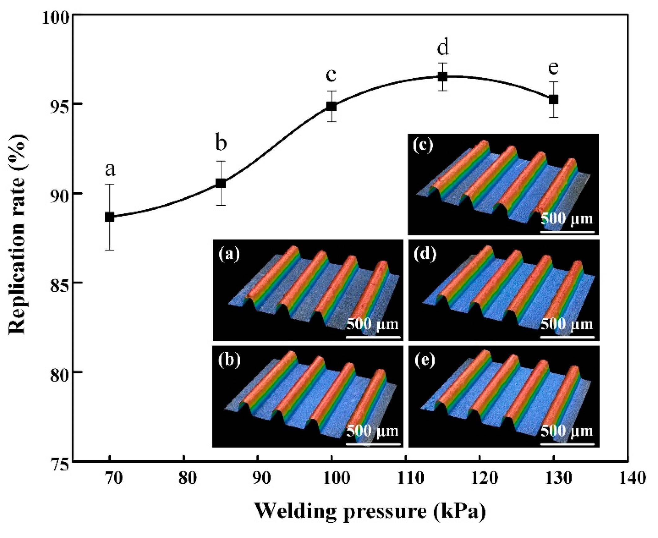
3.2. Influence of Welding Pressure on Molding Quality
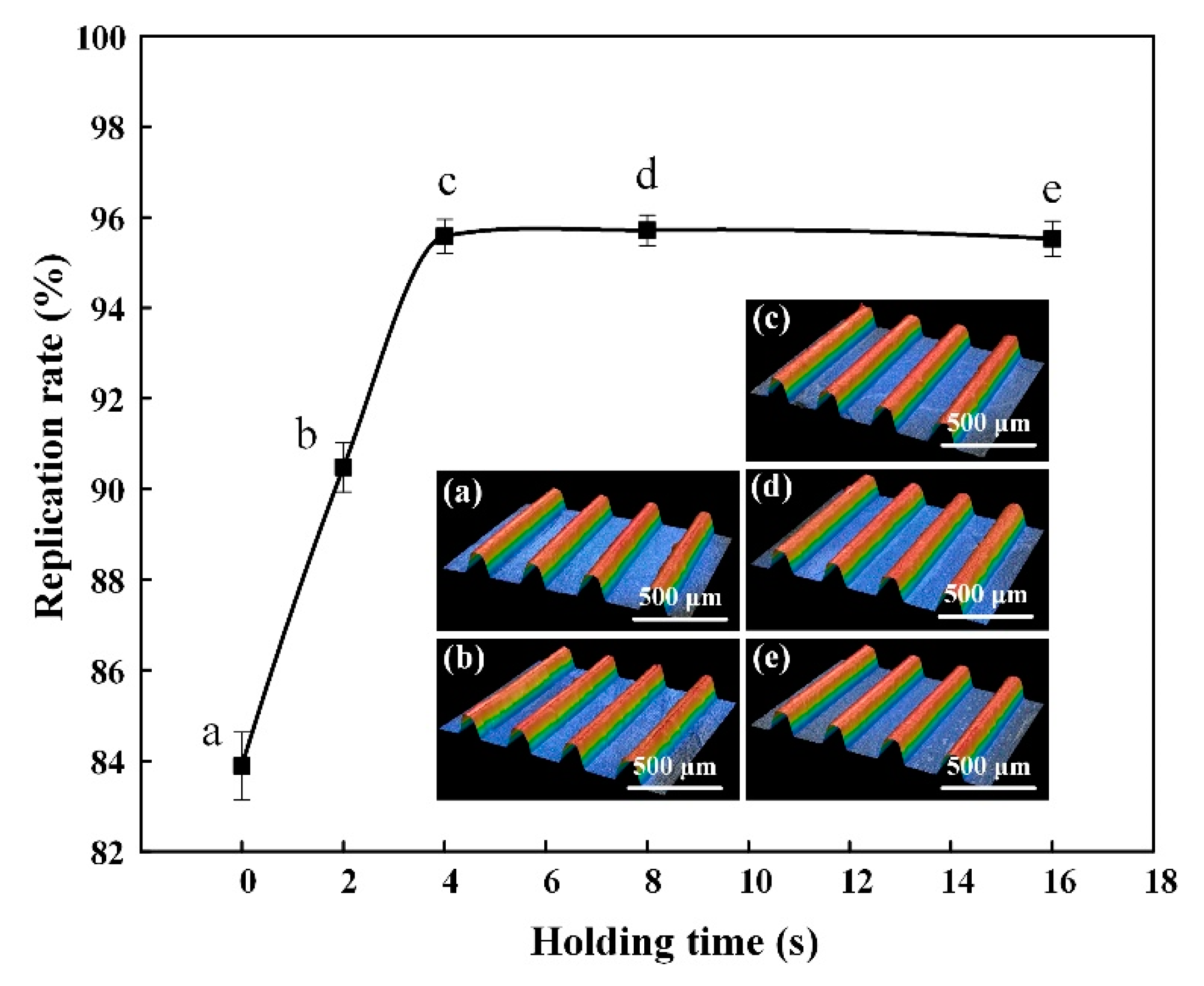
3.3. Influence of Holding Time on the Molding Quality
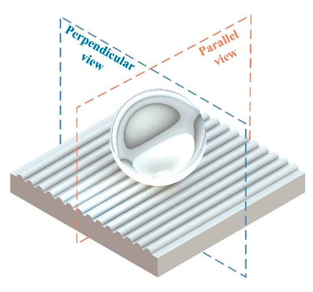
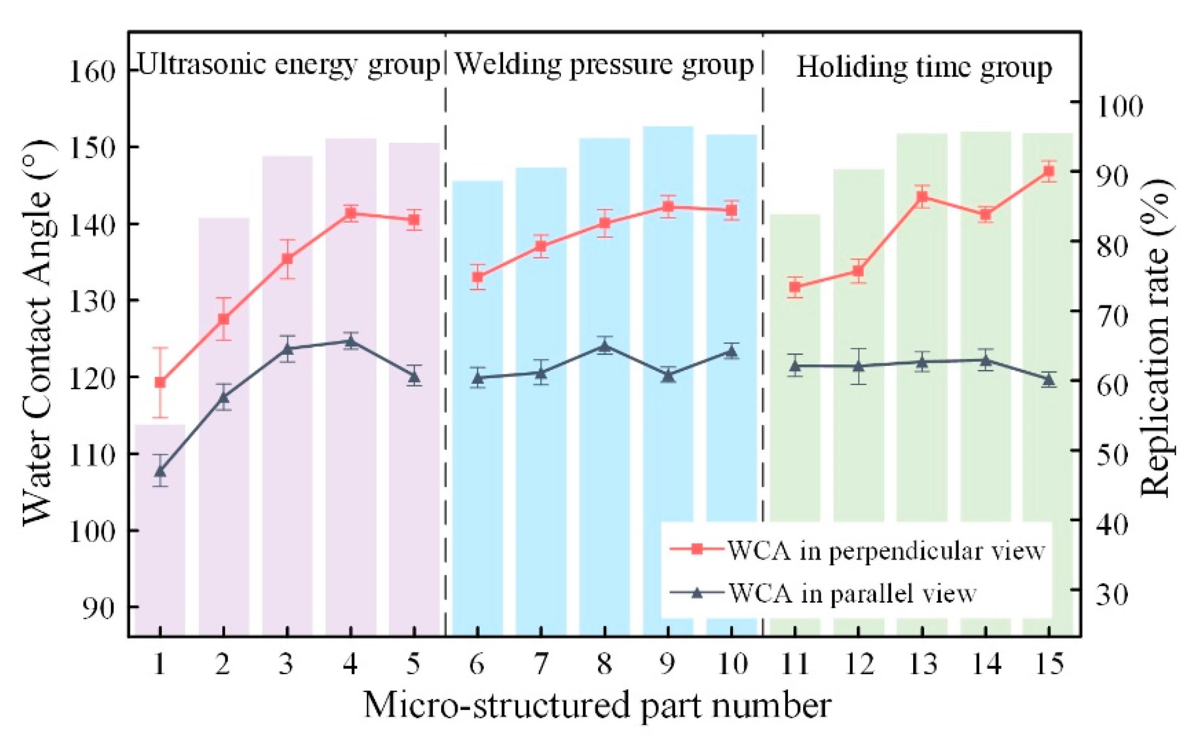
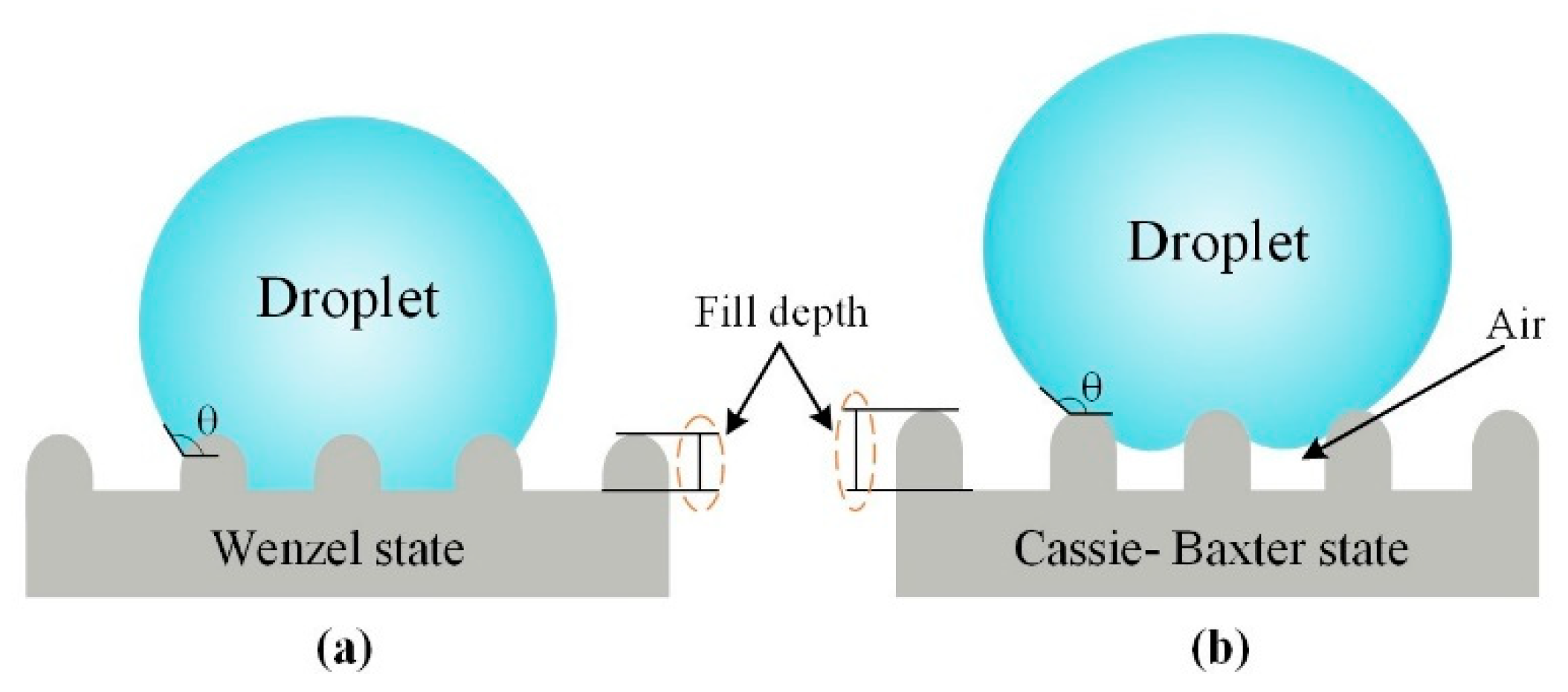
3.4. Wettability Properties
4. Conclusions
- (1)
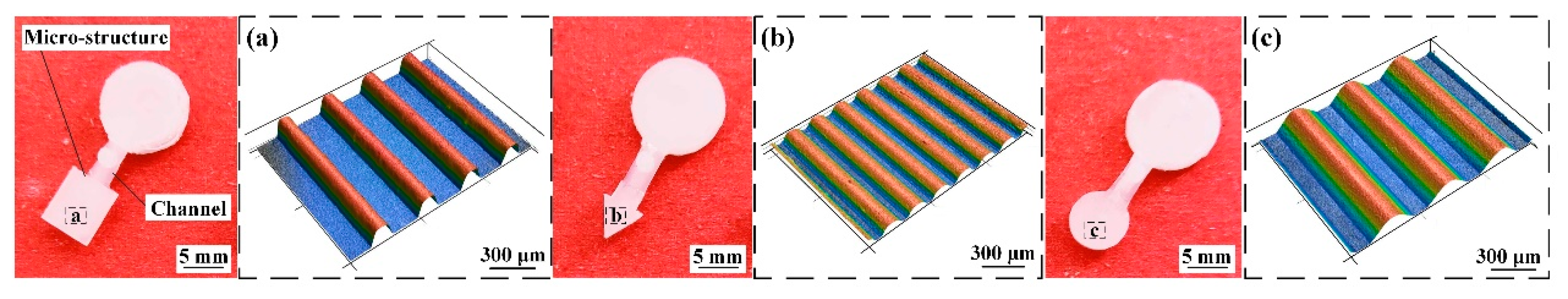
- A combined mold was assembled with an upper plate, a lower plate, a material chamber, a channel insert and a micro-structured core insert. Applying the combined mold in micro-UPM, the micro-structured parts with different shapes and sizes can be prepared, which has a simple process, low production cost and good flexibility.
- (2)
- The effect of ultrasonic energy, welding pressure and holding time was investigated for the fabricating of micro-structured PP parts during micro-UPM. The viscosity on the PP polymer was lower when ultrasonic energy is strengthened, leading to it filling in the micro-groove arrays more. Higher welding pressure allows PP melt to fill at a faster rate, reducing heat loss during the filling process. Besides, holding time is one of the critical parameters to prevent melting reflux and reduce product shrinkage and deformation. At the conditions of 1000 J, 115 kPa and 8 s, micro-structured parts with flexible shape and size can be successfully fabricated, the replication rate reaches about 96.52% and roughness Ra is about 0.85 μm.
- (3)
- By using the micro-structured core insert processed by WEDM-LS, micro-UPM successfully produced micro-structured parts with hydrophobic surface. The WCA in the perpendicular view on the micro-structured parts can reach a maximum of 146.8°.
- (4)
- The conclusions above are drawn from different trials, which proves the reproducibility of the molding process. However, more research on micro-UPM, such as the fabrication of composite materials, is still needed in the future.
Author Contributions
Funding
Conflicts of Interest
References
- Moon, I.Y.; Kim, B.H.; Lee, H.W.; Oh, Y.S.; Kim, J.H.; Kang, S.H. Superhydrophobic Polymer Surface with Hierarchical Patterns Fabricated in Hot Imprinting Process. Int. J. Precis. Eng. Manuf. Green Technol. 2020, 7, 493–503. [Google Scholar] [CrossRef]
- Vora, L.K.; Courtenay, A.J.; Tekko, I.A.; Larraneta, E.; Donnelly, R.F. Pullulan-based dissolving microneedle arrays for enhanced transdermal delivery of small and large biomolecules. Int. J. Biol. Macromol. 2020, 146, 290–298. [Google Scholar] [CrossRef] [PubMed]
- Huang, J.Y.; Wei, S.B.; Zhang, L.X.; Yang, Y.Y.; Yang, S.; Shen, Z.J. Fabricating the Superhydrophobic Nickel and Improving Its Antifriction Performance by the Laser Surface Texturing. Materials 2019, 12, 1155. [Google Scholar] [CrossRef] [PubMed]
- Huang, R.; Zhang, X.Q.; Ng, B.P.; Kumar, A.S.; Liu, K. Roll-to-Roll Embossing of Optical Radial Fresnel Lenses on Polymer Film for Concentrator Photovoltaics: A Feasibility Study. Int. J. Precis. Eng. Manuf. Green Technol. 2019, 12. [Google Scholar] [CrossRef]
- Milles, S.; Soldera, M.; Kuntze, T.; Lasagni, A.F. Characterization of self-cleaning properties on superhydrophobic aluminum surfaces fabricated by direct laser writing and direct laser interference patterning. Appl. Surf. Sci. 2020, 525, 146518. [Google Scholar] [CrossRef]
- Zhang, N.; Chu, J.S.; Byrne, C.J.; Browne, D.J.; Gilchrist, M.D. Replication of micro/nano-scale features by micro injection molding with a bulk metallic glass mold insert. J. Micromech. Microeng. 2012, 22, 13. [Google Scholar] [CrossRef]
- Maghsoudi, K.; Vazirinasab, E.; Momen, G.; Jafari, R. Advances in the Fabrication of Superhydrophobic Polymeric Surfaces by Polymer Molding Processes. Ind. Eng. Chem. Res. 2020, 59, 9343–9363. [Google Scholar] [CrossRef]
- Aguero, A.; Morcillo, M.D.; Quiles-Carrillo, L.; Balart, R.; Boronat, T.; Lascano, D.; Torres-Giner, S.; Fenollar, O. Study of the Influence of the Reprocessing Cycles on the Final Properties of Polylactide Pieces Obtained by Injection Molding. Polymers 2019, 11, 1908. [Google Scholar] [CrossRef]
- Peng, L.F.; Deng, Y.J.; Yi, P.Y.; Lai, X.M. Micro hot embossing of thermoplastic polymers: A review. J. Micromech. Microeng. 2014, 24, 23. [Google Scholar] [CrossRef]
- Maghsoudi, K.; Jafari, R.; Momen, G.; Farzaneh, M. Micro-nanostructured polymer surfaces using injection molding: A review. Mater. Today Commun. 2017, 13, 126–143. [Google Scholar] [CrossRef]
- Masato, D.; Babenko, M.; Shriky, B.; Gough, T.; Lucchetta, G.; Whiteside, B. Comparison of crystallization characteristics and mechanical properties of polypropylene processed by ultrasound and conventional micro-injection molding. Int. J. Adv. Manuf. Technol. 2018, 99, 113–125. [Google Scholar] [CrossRef]
- Chen, J.Y.; Chen, Y.Z.; Li, H.L.; Lai, S.Y.; Jow, J. Physical and chemical effects of ultrasound vibration on polymer melt in extrusion. Ultrason. Sonochem. 2010, 17, 66–71. [Google Scholar] [CrossRef] [PubMed]
- Sacristan, M.; Planta, X.; Morell, M.; Puiggali, J. Effects of ultrasonic vibration on the micro-molding processing of polylactide. Ultrason. Sonochem. 2014, 21, 376–386. [Google Scholar] [CrossRef]
- Grabalosa, J.; Ferrer, I.; Elias-Zuniga, A.; Ciurana, J. Influence of processing conditions on manufacturing polyamide parts by ultrasonic molding. Mater. Des. 2016, 98, 20–30. [Google Scholar] [CrossRef]
- Dorf, T.; Perkowska, K.; Janiszewska, M.; Ferrer, I.; Ciurana, J. Effect of the main process parameters on the mechanical strength of polyphenylsulfone (PPSU) in ultrasonic micro-moulding process. Ultrason. Sonochem. 2018, 46, 46–58. [Google Scholar] [CrossRef] [PubMed]
- Janer, M.; Planta, X.; Riera, D. Ultrasonic moulding: Current state of the technology. Ultrasonics 2020, 102, 14. [Google Scholar] [CrossRef]
- Jiang, B.Y.; Zou, Y.; Liu, T.; Wu, W.Q. Characterization of the Fluidity of the Ultrasonic Plasticized Polymer Melt by Spiral Flow Testing under Micro-Scale. Polymers 2019, 11, 357. [Google Scholar] [CrossRef]
- Lou, Y.; Xiong, J.J. Micro-Ultrasonic Viscosity Model Based on Ultrasonic-Assisted Vibration Micro-Injection for High-Flow Length Ratio Parts. Polymers 2020, 12, 522. [Google Scholar] [CrossRef]
- Gao, S.; Qiu, Z.J.; Ouyang, J.H. The Improvement Effect and Mechanism of Longitudinal Ultrasonic Vibration on the Injection Molding Quality of a Polymeric Micro-Needle Array. Polymers 2019, 11, 151. [Google Scholar] [CrossRef]
- Dorf, T.; Ferrer, I.; Ciurana, J. Characterizing Ultrasonic Micro-Molding Process of Polyetheretherketone (PEEK). Int. Polym. Process. 2018, 33, 442–452. [Google Scholar] [CrossRef]
- Ferrer, I.; Vives-Mestres, M.; Manresa, A.; Garcia-Romeu, M.L. Replicability of Ultrasonic Molding for Processing Thin-Wall Polystyrene Plates with a Microchannel. Materials 2018, 11, 1320. [Google Scholar] [CrossRef] [PubMed]
- Sanchez-Sanchez, X.; Hernandez-Avila, M.; Elizalde, L.E.; Martinez, O.; Ferrer, I.; Eliss-Zuniga, A. Micro injection molding processing of UHMWPE using ultrasonic vibration energy. Mater. Des. 2017, 132, 1–12. [Google Scholar] [CrossRef]
- Sanchez-Sanchez, X.; Elias-Zuniga, A.; Hernandez-Avila, M. Processing of ultra-high molecular weight polyethylene/graphite composites by ultrasonic injection moulding: Taguchi optimization. Ultrason. Sonochem. 2018, 44, 350–358. [Google Scholar] [CrossRef] [PubMed]
- Zhang, Y.; Hansen, H.N.; Sorensen, S. Replication of micro-pillars by PEEK injection moulding with CrN-coated Ni tool. Int. J. Adv. Manuf. Technol. 2015, 80, 383–388. [Google Scholar] [CrossRef]
- Liang, X.; Wu, X.Y.; Zeng, K.; Xu, B.; Wu, S.Y.; Zhao, H.; Li, B.; Ruan, S.C. Micro ultrasonic powder molding for semi-crystalline polymers. J. Micromech. Microeng. 2014, 24, 10. [Google Scholar] [CrossRef]
- Liang, X.; Wu, X.; Xu, B.; Ma, J.; Liu, Z.; Peng, T.; Fu, L. Phase structure development as preheating UHMWPE powder temperature changes in the micro-UPM process. J. Micromech. Microeng. 2016, 26, 015014. [Google Scholar] [CrossRef]
- Li, X.; Tian, H.G.; Zhang, W.W.; Zhang, S.C. Influence of Ultrasonic Transducer Structural Parameters on the Frictional Plasticizing Heat Generation of Polymer Particles. Int. Polym. Process. 2019, 34, 416–424. [Google Scholar] [CrossRef]
- Peng, T.; Jiang, B.Y.; Zou, Y. Study on the Mechanism of Interfacial Friction Heating in Polymer Ultrasonic Plasticization Injection Molding Process. Polymers 2019, 11, 1407. [Google Scholar] [CrossRef]
- Liang, X.; Liu, Y.-J.; Chen, S.-G.; Ma, J.; Wu, X.-Y.; Shi, H.-Y.; Fu, L.-Y.; Xu, B. Fabrication of microplastic parts with a hydrophobic surface by micro ultrasonic powder moulding. J. Manuf. Process. 2020, 56, 180–188. [Google Scholar] [CrossRef]
- Wenzel, R.N. Resistance of Solid Surfaces to Wetting by Water. Ind. Eng. Chem. 1936, 28, 988–994. [Google Scholar] [CrossRef]
- Cassie, A.; Baxter, S. Wettability of Porous Surfaces. Trans. Faraday Soc. 1944, 40, 546–551. [Google Scholar] [CrossRef]
- Wu, C.X.; Wu, X.Y.; Zhao, H.; Xu, B.; Zhu, L.K.; Liu, Y.F.; Gao, C. Effect of sub-millimetre morphologies on the hydrophobicity of a copper surface prepared by WEDM. Surf. Coat. Technol. 2020, 385, 9. [Google Scholar] [CrossRef]


| Process Parameters | Experiment 1 | Experiment 2 | Experiment 3 |
|---|---|---|---|
| A: Ultrasonic energy (J) | 400–1200 | 1000 | 1000 |
| B: Welding pressure (kPa) | 100 | 70–130 | 115 |
| C: Holding time (s) | 8 | 8 | 0–16 |
| Sample | Ultrasonic Energy (J) | Replication Rate (%) | Surface Roughness (μm) |
|---|---|---|---|
| 1# | 400 | 53.65 | 3.49 |
| 2# | 600 | 83.27 | 1.49 |
| 3# | 800 | 92.10 | 0.91 |
| 4# | 1000 | 94.57 | 0.87 |
| 5# | 1200 | 94.08 | 0.86 |
| Sample | Welding Pressure (kPa) | Replication Rate (%) | Surface Roughness (μm) |
|---|---|---|---|
| 6# | 70 | 88.67 | 1.02 |
| 7# | 85 | 90.56 | 0.95 |
| 8# | 100 | 94.86 | 0.88 |
| 9# | 115 | 96.52 | 0.85 |
| 10# | 130 | 95.23 | 0.90 |
| Sample | Holding Time (s) | Replication Rate (%) | Surface Roughness (μm) |
|---|---|---|---|
| 11# | 0 | 83.87 | 1.37 |
| 12# | 2 | 90.47 | 1.12 |
| 13# | 4 | 95.57 | 0.88 |
| 14# | 8 | 95.71 | 0.85 |
| 15# | 16 | 95.55 | 0.88 |
| Structure-Free Surface | Sample 1# | Sample 2# | Sample 3# | Sample 4# | Sample 5# | |
|---|---|---|---|---|---|---|
| Perpendicular view |  |  |  |  |  |  |
| Parallel view |  |  |  |  |  |  |
© 2020 by the authors. Licensee MDPI, Basel, Switzerland. This article is an open access article distributed under the terms and conditions of the Creative Commons Attribution (CC BY) license (http://creativecommons.org/licenses/by/4.0/).
Share and Cite
Liang, X.; Liu, Y.; Ma, J.; Gong, F.; Lou, Y.; Fu, L.; Xu, B. Fabrication of Micro Ultrasonic Powder Molding Polypropylene Part with Hydrophobic Patterned Surface. Materials 2020, 13, 3247. https://doi.org/10.3390/ma13153247
Liang X, Liu Y, Ma J, Gong F, Lou Y, Fu L, Xu B. Fabrication of Micro Ultrasonic Powder Molding Polypropylene Part with Hydrophobic Patterned Surface. Materials. 2020; 13(15):3247. https://doi.org/10.3390/ma13153247
Chicago/Turabian StyleLiang, Xiong, Yongjing Liu, Jiang Ma, Feng Gong, Yan Lou, Lianyu Fu, and Bin Xu. 2020. "Fabrication of Micro Ultrasonic Powder Molding Polypropylene Part with Hydrophobic Patterned Surface" Materials 13, no. 15: 3247. https://doi.org/10.3390/ma13153247
APA StyleLiang, X., Liu, Y., Ma, J., Gong, F., Lou, Y., Fu, L., & Xu, B. (2020). Fabrication of Micro Ultrasonic Powder Molding Polypropylene Part with Hydrophobic Patterned Surface. Materials, 13(15), 3247. https://doi.org/10.3390/ma13153247