On Influence of Mechanical Properties of Gun Propellants on Their Ballistic Characteristics Determined in Closed Vessel Tests


Abstract
1. Introduction
- the parameters of the barrel: capacity of the chamber Wo, barrel cross-sectional area s, secondary works coefficient φ,
- the mass of the projectile mp and its velocity vp(t) attained at a given projectile path l(t); thermodynamic parameters of propellant gases: force f, covolume η, and ratio of specific heats k (θ = k − 1),
- the relative burned volume of propellant grain z (ratio of the burned volume to the initial volume), and
- the mass ω and the density ρ of the propellant, as well as the shapes and sizes of the propellant grains.
- all propellant grains are ignited at the same time,
- propellant grains burn in parallel layers,
- the burning rate is only a function of the pressure, and
- there is no cracking of grains.
2. Materials and Experimental Procedure
2.1. Propellant Materials
2.2. Strength Compression Experiments
2.2.1. Specimen Preparation
2.2.2. Quasi-Static Compression Testing
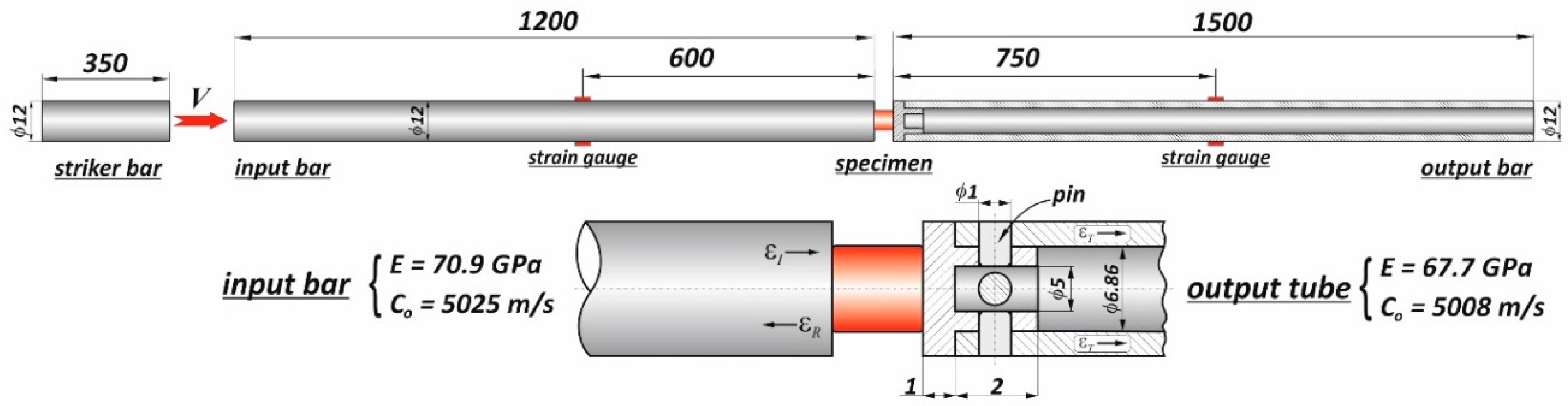
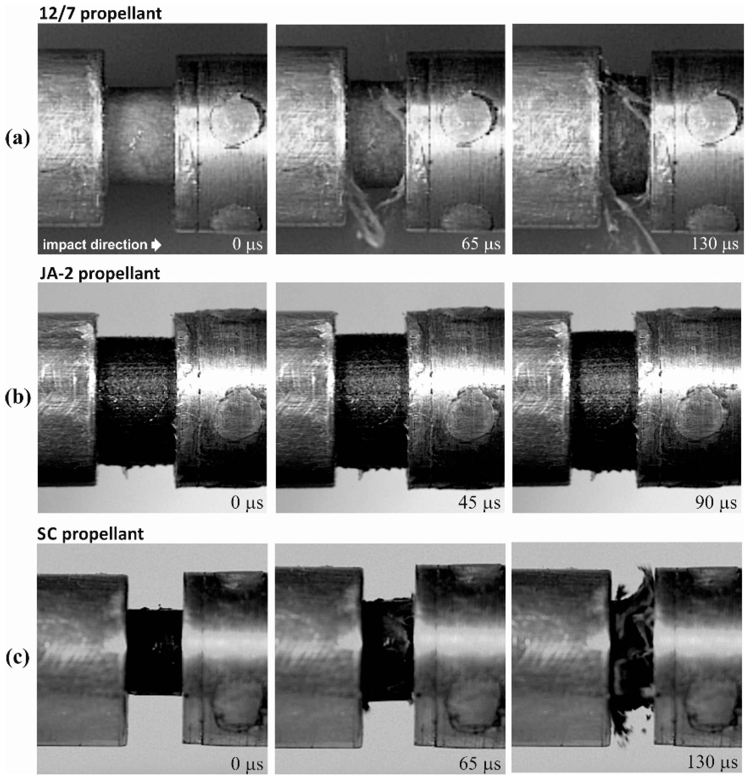
2.2.3. High Strain Rates Compression Testing
2.3. Closed Vessel Tests and Method of Closed Vessel Test Data Reduction
3. Results and Discussion
3.1. Mechanical Testing Analysis
3.2. Analysis of Closed Vessel Tests Results
4. Conclusions
Author Contributions
Funding
Conflicts of Interest
References
- Serebryakov, M. Internal Ballistics; Oborongiz: Moscow, Russia, 1949. (In Russian) [Google Scholar]
- Corner, J. Theory of the Interior Ballistics of Guns; John Wiley & Sons, Inc.: New York, NY, USA, 1950. [Google Scholar]
- Baer, P.G. Practical Interior Ballistic Analysis of Guns; Progress in Astronautics and Aeronautics, Volume 66—Interior Ballistics of Guns; American Institute of Aeronautics and Astronautics: Washington, DC, USA, 1979; pp. 37–66. [Google Scholar]
- Military Standard MIL-STD 286 C. In Propellants, Solid: Sampling, Examination and Testing. Method 501.1. Compressibility of Grains; US Army ARDEC Standardization Office: Picatinny Arsenal, NJ, USA, 1991.
- Boulkadid, K.M.; Lefebvre, M.H.; Jeunieau, L.A.; Dejeaifve, L.A. Mechanical and ballistic properties of spherical single base gun propellant. Cent. Eur. J. Energy Mater. 2017, 14, 90–104. [Google Scholar] [CrossRef]
- Nicolaides, S.; Wiegand, D.A.; Pinto, J. The mechanical behavior of gun propellant grains in interior ballistics. In Technical Report AP.LCD-TR-82010; Army Armament Research and Development Command: Dover, NJ, USA, 1982. [Google Scholar]
- Robert, L.L. The Mechanical response of M30, JA2 and XM39 Gun propellants to high-rate deformation. In Technical Report BRL-TR-3023; US Army Ballistic Research Laboratory, Aberdeen Proving Ground: Aberdeen, MD, USA, 1989. [Google Scholar]
- Gazonas, G.A. The Mechanical Response of M30, XM39, and JA2 Propellants at Strain Rates from 10-2 to 250 sec-1. In Technical Report BRL-TR-3181; US Army Ballistic Research Laboratory, Aberdeen Proving Ground: Aberdeen, MD, USA, 1991. [Google Scholar]
- Gazonas, G.A. A Uniaxial, Nonlinear thermoviscoelastic constitutive model with damage for M30 gun propellant. In Technical Report ARL-TR-469; US Army Ballistic Research Laboratory, Aberdeen Proving Ground: Aberdeen, MD, USA, 1994. [Google Scholar]
- Zhang, H.; Zhou, J.; Yang, L.X.; Zhao, B.M.; Liu, L.D. Effects of temperature on the dynamic mechanical properties of granular gun propellant. Chin. J. Explos. Propellants 2015, 38, 86–88. [Google Scholar]
- Liu, J.; Cheng, S.; Wang, Y.H.; Ma, Z.L.; Xiao, Z.L. Study on mechanical properties of gun-propellants with RDX.doc. Adv. Mater. Res. 2014, 884–885, 154–157. [Google Scholar] [CrossRef]
- Zhang, F.; Zhu, D.; Liu, Q.; Liu, Z.; Du, P. Study on the effect of RDX content on the properties of Nitramine propellant. Def. Technol. 2017, 13, 246–248. [Google Scholar] [CrossRef]
- Lieb, R.J.; Rocchio, J.R. A Gas Gun Impact Tester for Solid Gun Propellants. In Memorandum Report BRL-MR-3399; US Army Ballistic Research Laboratory, Aberdeen Proving Ground: Aberdeen, MD, USA, 1984. [Google Scholar]
- Hoffman, H.J. High-Strain Rate Testing of Gun Propellants. In Chemical Propulsion Information Agency Publication 502; The Johns Hopkins University, Applied Physics Laboratory: Laurel, MD, USA, 1988. [Google Scholar]
- Lieb, R.J. High Strain Rate Response of Gun Propellant Using the Hopkinson Split Bar. In Technical Report BRL-TR-3200; US Army Ballistic Research Laboratory, Aberdeen Proving Ground: Aberdeen, MD, USA, 1991. [Google Scholar]
- Ho, S.Y. High strain-rate impact studies of predamaged rocket propellants. I. Characterization of damage using a cumulative damage failure criterion. Combust. Flame 1996, 104, 524–534. [Google Scholar] [CrossRef]
- Khan, M.J.; Xiong, C.; Xin, T.; Ullah, H.; Ullah, A.; Musa, O. Incorporating mechanical properties of HTPB propellant to a viscohyperelastic constitutive model over a large range of strain rates. N. Y. Sci. J. 2017, 10, 94–100. [Google Scholar]
- Wang, Z.; Qiang, H.; Wang, T.; Wang, G.; Hou, X. A thermovisco-hyperelastic constitutive model of HTPB propellant with damage at intermediate strain rates. Mech. Time-Depend. Mater. 2018, 22, 291–314. [Google Scholar] [CrossRef]
- Manning, G.T.; Leone, J.; Zebregs, M.; Ramlal, R.D.; van Driel, A.C. Definition of a JA-2 Equivalent propellant to be produced by continuous solventless extrusion. J. Appl. Mech. 2013, 80, 3. [Google Scholar] [CrossRef]
- Czyżewska, M.; Fikus, B.; Leciejewski, Z.; Michalski, J.; Surma, Z.; Trębiński, R. Ballistic analysis of Polish low-vulnerability gun propellants. Probl. Mechatron. Armament Aviat. Saf. Eng. 2018, 9, 75–92. [Google Scholar] [CrossRef]
- Chen, W.; Song, B. Split Hopkinson (Kolsky) Bar, Design, Testing and Applications; Springer: Berlin/Heidelberg, Germany, 2011. [Google Scholar]
- Gray, G.T., III. Mechanical Testing and Evaluation. In ASM Handbook; Kuhn, H., Medlin, D., Eds.; ASM International: Novelty, OH, USA, 2000; Volume 8, pp. 939–1270. [Google Scholar]
- Chen, W.; Zhang, B.; Forrestal, M.J. A split Hopkinson bar technique for low-impedance materials. Exp. Mech. 1999, 39, 81–85. [Google Scholar] [CrossRef]
- Chen, W.; Lu, F.; Zhou, B. A quartz-crystal-embedded Split hopkinson pressure bar for soft materials. Exp. Mech. 2000, 40, 1–6. [Google Scholar] [CrossRef]
- Song, B.; Chen, W. One-dimensional dynamic compressive behaviour of EPDM rubber. J. Eng. Mater. Technol. 2003, 125, 294–301. [Google Scholar] [CrossRef]
- Kolsky, H. Propagation of stress waves in viscoelastic solids. Appl. Mech. Rev. 1958, 11, 465–468. [Google Scholar] [CrossRef]
- Trebinski, R.; Leciejewski, Z.; Surma, Z. Modifications of the closed vessel test results analysis method. In Proceedings of the 31st International Symposium on Ballistics, Hyderabad, India, 4–7 November 2019. [Google Scholar]
- Cleveland, W.S. Robust locally weighted regression and smoothing scatterplots. J. Am. Stat. Assoc. 1979, 74, 829–836. [Google Scholar] [CrossRef]
- Niu, L.; Cao, M.; Liang, Z.; Han, B.; Zhang, Q. A modified Johnson-Cook model considering strain softening of A356 alloy. Mater. Sci. Eng. A 2020, 139612. [Google Scholar] [CrossRef]
- Kooker, D.E.; Sandusky, H.W.; Elban, W.L.; Conroy, P.J. Quasi-static compaction of large-caliber granular gun propellant. In Proceedings of the 15th International Symposium on Ballistics, Jerusalem, Israel, 21–24 May 1995; Volume 3, pp. 1–9. [Google Scholar]
- Assovskiy, Y.G. Physics of Combustion and Internal Ballistics; Nauka: Moscow, Russia, 2005. (In Russian) [Google Scholar]
- Trębiński, R.; Leciejewski, Z.; Surma, Z.; Fikus, B. Analysis of dynamic vivacity curves obtained on the basis of valved closed vessel test data. In Proceedings of the 30th International Symposium on Ballistics, Long Beach, CA, USA, 11–15 September 2017; Volume 1, pp. 496–504. [Google Scholar]


| NC 1 | DFA 2 | Volatiles |
|---|---|---|
| 95.2 | 1.5 | 3.3 |
| NC 1 | NG 2 | DEGDN 3 | Akardite II | Graphite |
|---|---|---|---|---|
| 59.5 | 14.9 | 24.8 | 0.7 | 0.1 |
| RDX 1 | NC 2 | CAB 3 | TAC 4 | Other |
|---|---|---|---|---|
| 75 | 10 | 6 | 7 | 2 |
| Parameter | 12/7 | JA-2 [20] | SC [20] |
|---|---|---|---|
| Grain shape | cylindrical | cylindrical | cylindrical |
| Perforation number | 7 | 7 | 7 |
| Length L [mm] | 14.55 | 15.5 | 8.7 |
| Diameter D [mm] | 6.6 | 8.8 | 6.3 |
| Perforation diameter d [mm] | 0.6 | 0.55 | 0.58 |
| Web thickness [mm] | 1.2 | 1.78 | 1.14 |
| Test | T1 | T2 | T3 | T4 | T5 | T6 | T7 | T8 | T9 | T10 | T11 | T12 | T13 |
|---|---|---|---|---|---|---|---|---|---|---|---|---|---|
| 12/7 | 1090 | 1420 | 1720 | 1730 | 1980 | 2540 | 2730 | 2870 | - | - | - | - | - |
| JA-2 | 1920 | 2270 | 2380 | 2660 | 3170 | 3710 | 3900 | - | - | - | - | - | - |
| SC | 1950 | 2110 | 2120 | 2410 | 2610 | 2780 | 2920 | 3040 | 3190 | 3450 | 3920 | 4250 | 5820 |
| Parameter | 12/7 | JA-2 [20] | SC [20] |
|---|---|---|---|
| Force (E) [kJ/kg] | 1096 | 963 | 968 |
| Force (Q) [kJ/kg] | 1260 | 1167 | 1113 |
| Covolume (E) [dm3/kg] | 0.967 | 1.465 | 1.608 |
| Covolume (Q) [dm3/kg] | 0.516 | 1.011 | 1.233 |
| Exponent (E) | 0.779 | 0.841 | 0.872 |
| Exponent (Q) | 0.898 | 1.014 | 0.980 |
© 2020 by the authors. Licensee MDPI, Basel, Switzerland. This article is an open access article distributed under the terms and conditions of the Creative Commons Attribution (CC BY) license (http://creativecommons.org/licenses/by/4.0/).
Share and Cite
Trębiński, R.; Janiszewski, J.; Leciejewski, Z.; Surma, Z.; Kamińska, K. On Influence of Mechanical Properties of Gun Propellants on Their Ballistic Characteristics Determined in Closed Vessel Tests. Materials 2020, 13, 3243. https://doi.org/10.3390/ma13143243
Trębiński R, Janiszewski J, Leciejewski Z, Surma Z, Kamińska K. On Influence of Mechanical Properties of Gun Propellants on Their Ballistic Characteristics Determined in Closed Vessel Tests. Materials. 2020; 13(14):3243. https://doi.org/10.3390/ma13143243
Chicago/Turabian StyleTrębiński, Radosław, Jacek Janiszewski, Zbigniew Leciejewski, Zbigniew Surma, and Kinga Kamińska. 2020. "On Influence of Mechanical Properties of Gun Propellants on Their Ballistic Characteristics Determined in Closed Vessel Tests" Materials 13, no. 14: 3243. https://doi.org/10.3390/ma13143243
APA StyleTrębiński, R., Janiszewski, J., Leciejewski, Z., Surma, Z., & Kamińska, K. (2020). On Influence of Mechanical Properties of Gun Propellants on Their Ballistic Characteristics Determined in Closed Vessel Tests. Materials, 13(14), 3243. https://doi.org/10.3390/ma13143243