Wide-Gap Brazing of K417G Alloy Assisted by In Situ Precipitation of M3B2 Boride Particles


Abstract
1. Introduction
2. Materials and Methods
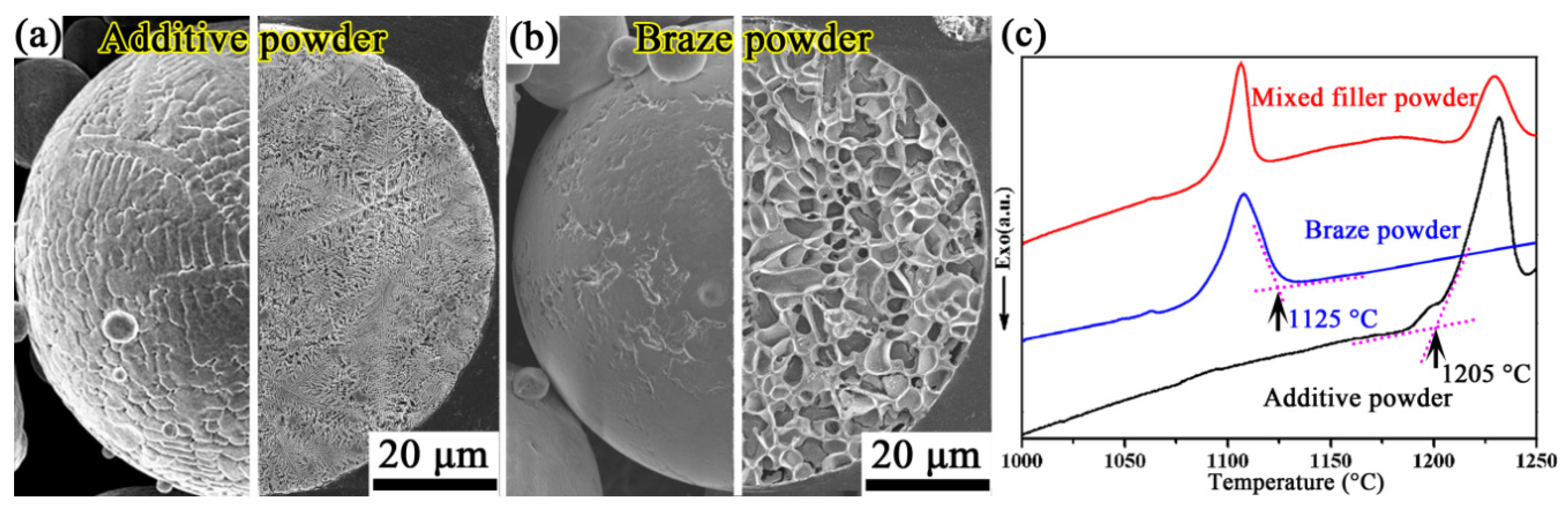
2.1. Materials
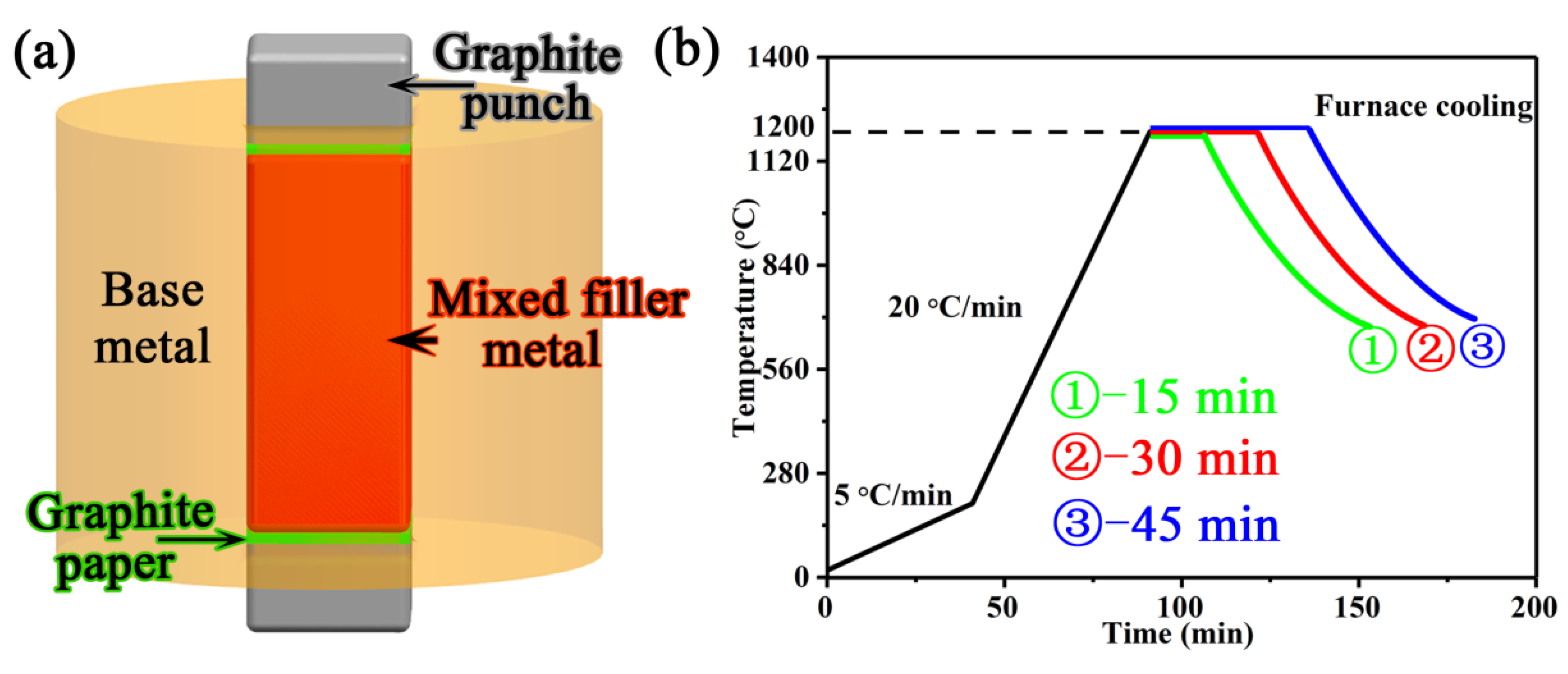
2.2. Brazing Method
2.3. Microstructure and Properties Characterization
3. Results
3.1. Microstructure of Wide-Gap Brazed Region
3.2. Mechanical Properties
4. Discussion
5. Conclusions
- (1)
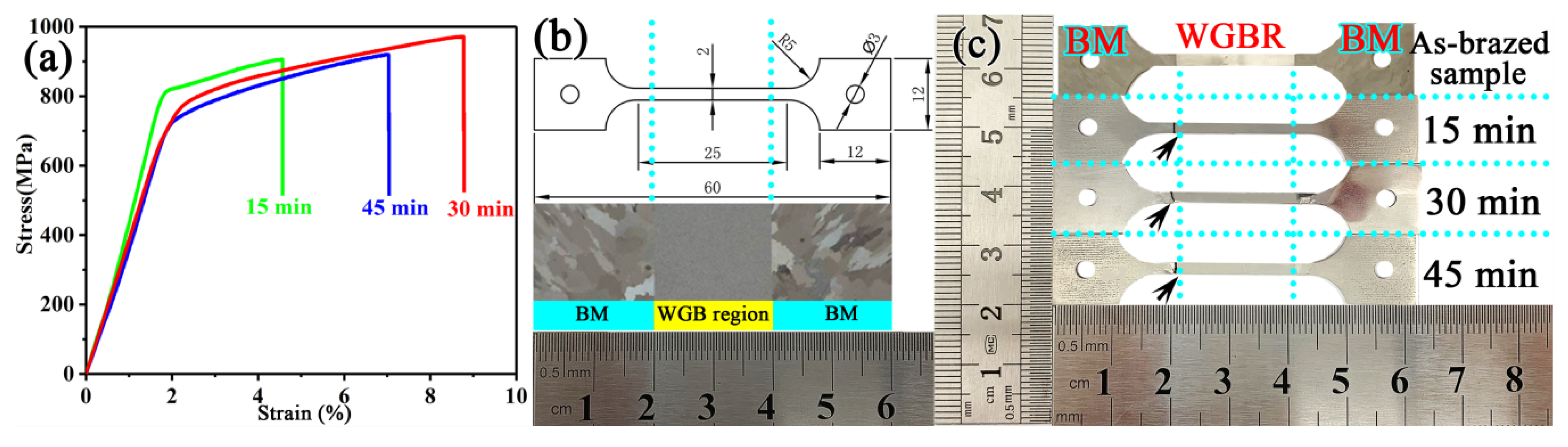
- With the increase of the brazing time from 15 to 45 min, the tensile strength of the repaired joint increased initially and then decreased. The maximum UTS value of the joint was obtained by brazing for 30 min and was 971 MPa at room temperature, which was higher than that of the cast BM.
- (2)
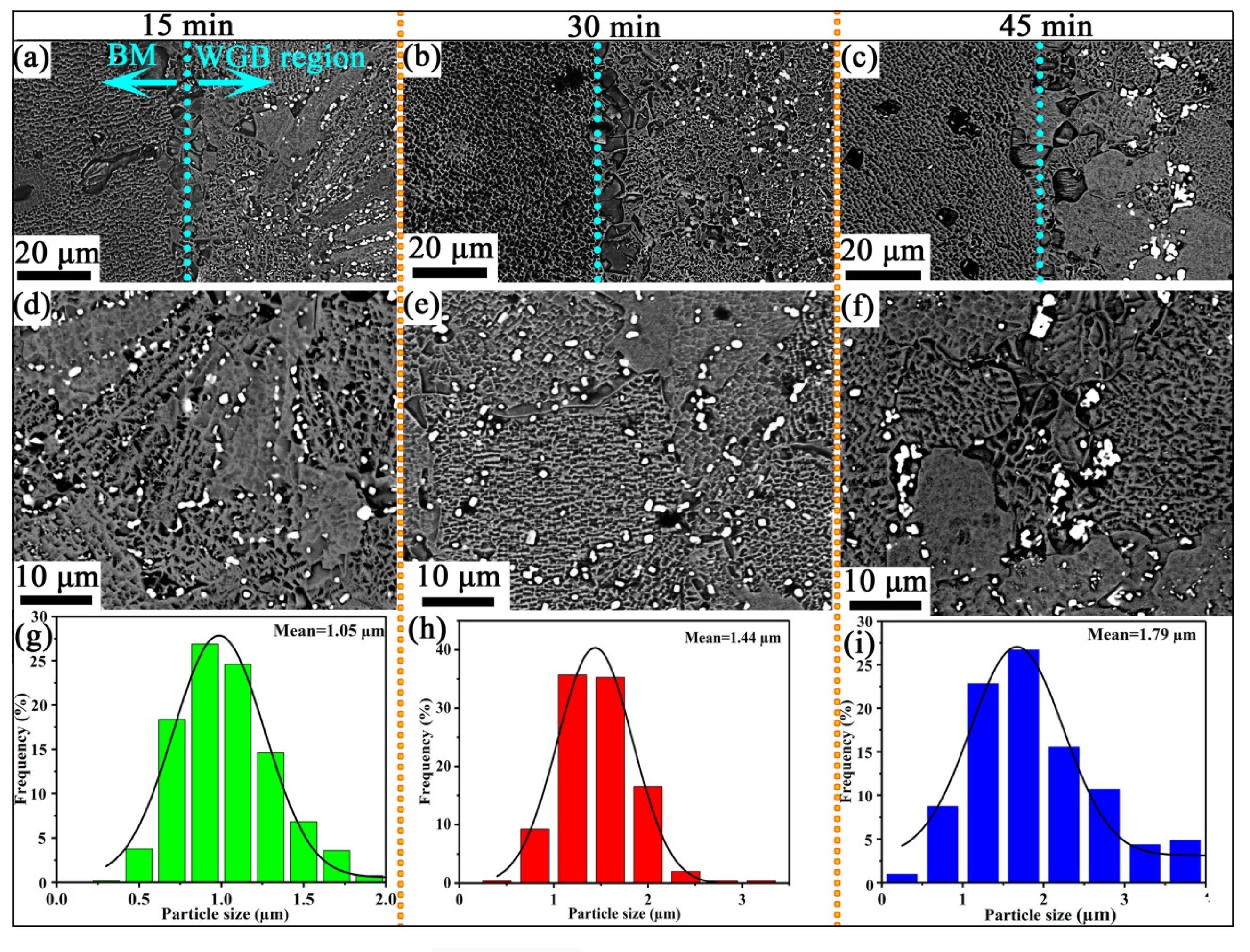
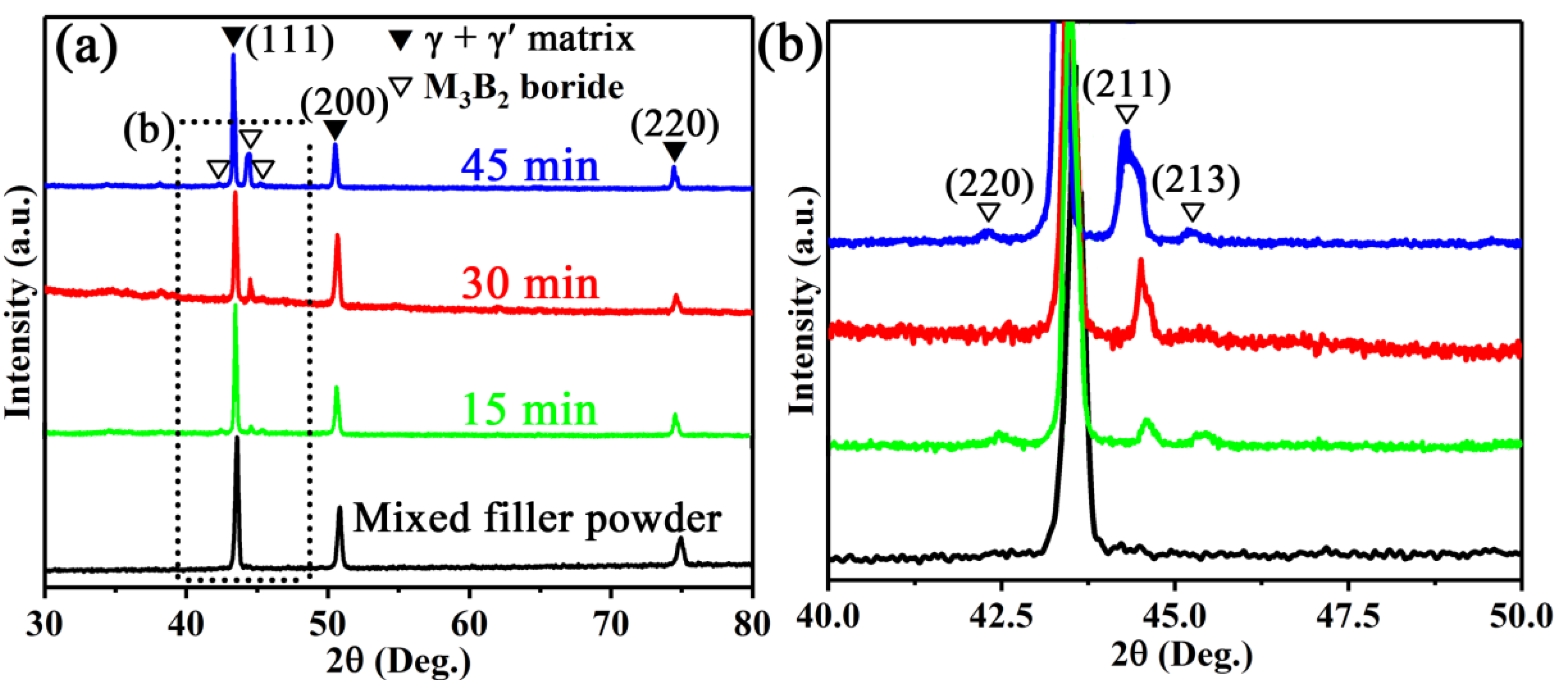
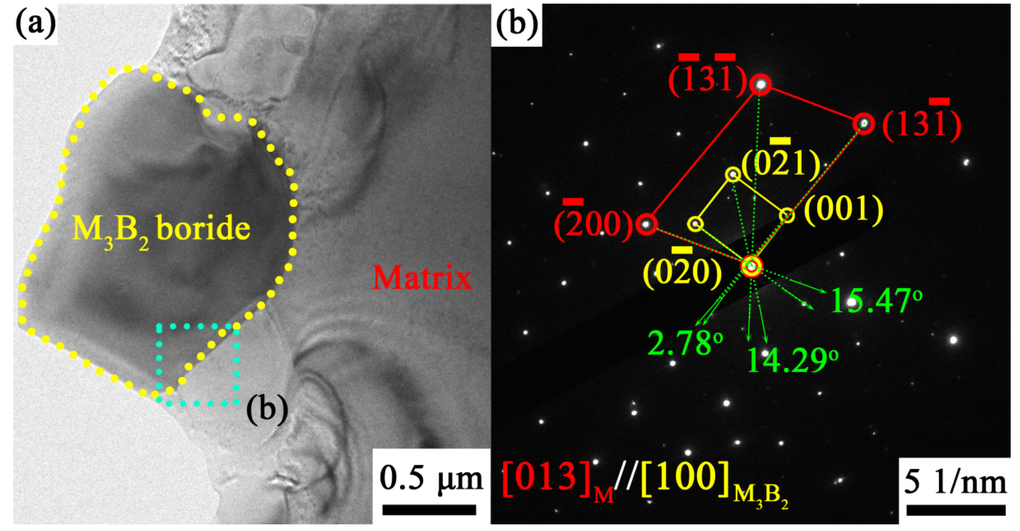
- At the brazing times of 15 min, the M3B2 boride particles were mainly distributed at the dendrite boundary, and their size was fine. The M3B2 boride particles in the joint brazed for 30 min exhibited the most uniform size and semi-coherently precipitated in the matrix, with an approximate spherical size of about ~1.44 μm. When the brazing time was further increased to 45 min, the grains and particles coarsened. Therefore, 30 min was determined to be the optimal brazing time to obtain high performance.
- (3)
- The improvement of the strength of the K417G alloy brazed for 30 min is mainly due to the coherent strain strengthening between the dispersed M3B2 particles and its γ + γ′ matrix, as well as the mirror-deformation resistance caused by the inconsistency of the deformation between the hard particle and the soft matrix.
Author Contributions
Funding
Acknowledgments
Conflicts of Interest
References
- Gong, L.; Chen, B.; Zhang, L.; Ma, Y.; Liu, K. Effect of cooling rate on microstructure, microsegregation and mechanical properties of cast Ni-based superalloy K417G. J. Mater. Sci. Technol. 2018, 34, 811–820. [Google Scholar] [CrossRef]
- Du, B.N.; Yang, J.X.; Cui, C.Y.; Sun, X.F. Effects of grain refinement on the microstructure and tensile behaviour of K417G superalloy. Mater. Sci. Eng. A. 2015, 623, 59–67. [Google Scholar] [CrossRef]
- Jia, W.; Chen, S.; Wei, M.; Liang, J.; Liu, C.; Li, J. Characteristics, and printability of K417G nickel-base alloy powder prepared by VIGA method. Powder Met. 2018, 62, 30–37. [Google Scholar] [CrossRef]
- Liao, Z.; Polyakov, M.; Diaz, O.G.; Axinte, D.; Mohanty, G.; Maeder, X.; Michler, J.; Hardy, M. Grain refinement mechanism of nickel-based superalloy by severe plastic deformation—Mechanical machining case. Acta Mater. 2019, 180, 2–14. [Google Scholar] [CrossRef]
- Kil-Kim, J.; Park, H.J.; Shim, D.N.; Kim, D.J. Transient liquid phase bonding of γ′- precipitation strengthened Ni based superalloys for repairing gas turbine components. J. Manuf. Process. 2017, 25, 60–69. [Google Scholar] [CrossRef]
- Baharzadeh, E.; Shamanian, M.; Rafiei, M.; Mostaan, H. Properties of IN X-750/BNi-2/SAF 2205 joints formed by transient liquid phase bonding. J. Mater. Process. Technol. 2019, 274, 1–11. [Google Scholar] [CrossRef]
- Bakhtiari, R.; Shamsabadi, A.Y.; Moredi, K.A. Shear strength/microstructure relationship for dissimilar IN738/IN718 TLP joints. Weld World 2019, 64, 219–231. [Google Scholar] [CrossRef]
- Arhami, F.; Mirsalehi, S.E.; Sadeghian, A.K. Effect of bonding time on microstructure and mechanical properties of diffusion brazed IN-939. J. Mater. Process. Technol. 2019, 265, 219–229. [Google Scholar] [CrossRef]
- Kil-Kim, J.; Park, H.J.; Shim, D.N.; Kim, D.J. Effect of bonding parameters on microstructural characteristics during TLP bonding of directionally solidified Ni-based superalloy. J. Manuf. Process. 2017, 30, 208–216. [Google Scholar] [CrossRef]
- Liu, D.; Song, Y.; Shi, B.; Zhang, Q.; Song, X.; Niu, H.; Feng, J. Vacuum brazing of GH99 superalloy using graphene reinforced BNi-2 composite filler. J. Mater. Sci. Technol. 2018, 34, 1843–1850. [Google Scholar] [CrossRef]
- Liu, M.-C.; Sheng, G.-M.; He, H.-J.; Jiao, Y.-J. Microstructural evolution, and mechanical properties of TLP bonded joints of Mar-M247 superalloys with Ni-Cr-Co-W-Ta-B interlayer. J. Mater. Process. Technol. 2017, 246, 245–251. [Google Scholar] [CrossRef]
- Pilehrood, A.E.; Omidvar, H.; Shamsipur, A.; Khakian-Ghomi, M. Effect of transient liquid phase bonding followed by homogenization on the microstructure and hot tensile behavior of Inconel 738 superalloy. J. Manuf. Process. 2019, 48, 110–118. [Google Scholar] [CrossRef]
- Yan, G.; Bhowmik, A.; Nagarajan, B.; Song, X.; Tan, S.C.; Tan, M.J. Bonding temperature effects on the wide gap transient liquid phase bonding of Inconel 718 using BNi-2 paste filler metal. Appl. Surf. Sci. 2019, 484, 1223–1233. [Google Scholar] [CrossRef]
- Wang, G.; Sun, Y.; Wang, X.; Liu, J.; Liu, J.; Li, J.; Yu, J.; Zhou, Y.; Jin, T.; Sun, X.; et al. Microstructure evolution and mechanical behavior of Ni-based single crystal superalloy joint brazed with mixed powder at elevated temperature. J. Mater. Sci. Technol. 2017, 33, 1219–1226. [Google Scholar] [CrossRef]
- Demo, W.D.; Ferrigno, S.J. Brazing Method Helps Repair Aircraft Gas-Turbine Nozzles. Adv. Mater. Process 1992, 141, 43–45. [Google Scholar]
- McGuire, D.; Huang, X.; Nagy, D.; Chen, W. Effect of Tungsten Addition on the Nucleation of Borides in Wide Gap Brazed Joint. J. Eng. Gas Turbines Power 2010, 132, 062101. [Google Scholar] [CrossRef]
- Liu, Y.; Pan, H.; Zhao, H.; Zhang, X.; Cheng, Y. The microstructures and mechanical properties of K465 superalloy joints, brazed with different clearances. Weld. World 2015, 60, 93–98. [Google Scholar] [CrossRef]
- Yu, Y.H.; Lai, M.O. Effects of gap filler and brazing temperature on fracture and fatigue of wide-gap brazed joints. J. Mater. Sci. 1995, 30, 2101–2107. [Google Scholar] [CrossRef]
- Way, M.; Willingham, J.; Goodall, R. Brazing filler metals. Int. Mater. Rev. 2019, 65, 257–285. [Google Scholar] [CrossRef]
- Huang, X.; Miglietti, W. Wide Gap Braze Repair of Gas Turbine Blades and Vanes—A Review. J. Eng. Gas Turbines Power 2011, 134, 010801. [Google Scholar] [CrossRef]
- Lim, L.C.; Lee, W.Y.; Lai, M.O. Nickel base wide gap brazing with preplacement technique part 1—Effect of material and process parameters on formation of macrovoids. Mater. Sci. Technol. 1995, 11, 1041–1045. [Google Scholar] [CrossRef]
- Zhang, J.; Zhang, Z.; Sun, J.; Liu, X. Effect of Gap Filler on Microstructure of Wide Gap Brazing Seam. Mater. Trans. JIM 2000, 41, 1073–1076. [Google Scholar] [CrossRef][Green Version]
- Nagy, D.; Huang, X. Wide Gap Braze Repair Using Vertically Laminated Repair Scheme. J. Eng. Gas Turbines Power 2008, 131, 012101. [Google Scholar] [CrossRef]
- Osoba, L.O.; Ojo, O.A. Influence of Solid-State Diffusion during Equilibration on Microstructure and Fatigue Life of Superalloy Wide-Gap Brazements. Met. Mater. Trans. A 2013, 44, 4020–4024. [Google Scholar] [CrossRef]
- Corbin, S.F.; Murray, D.C.; Bouthillier, A. Analysis of Diffusional Solidification in a Wide-Gap Brazing Powder Mixture Using Differential Scanning Calorimetry. Met. Mater. Trans. A 2016, 47, 6339–6352. [Google Scholar] [CrossRef]
- Cheng, Z.; Li, X.; Wang, B.; Qu, S.; Li, H. M3B2-type borides effect on the wide gap brazing of K417G alloy with mixed powder. J. Alloy. Compd. 2020, 821, 153431. [Google Scholar] [CrossRef]
- Hu, Z.; Li, W.; Zhao, Y. The Effect of Laser Power on the Properties of M3B2-Type Boride-Based Cermet Coatings Prepared by Laser Cladding Synthesis. Materials 2020, 13, 1867. [Google Scholar] [CrossRef]
- Wang, H.Q.; Sun, J.S.; Li, C.N.; Geng, S.N.; Sun, H.G.; Wang, G.L. Microstructure, and mechanical properties of molybdenum–iron–boron–chromium cladding using argon arc welding. Mater. Sci. Technol. 2016, 32, 1694–1701. [Google Scholar] [CrossRef]
- Bai, K.; Ng, F.L.; Tan, T.L.; Li, T.; Pan, D.; Dayou, P. Understanding non-parabolic solidification kinetics in Ni-based alloys during TLP bonding via thermo-kinetic modelling. J. Alloy. Compd. 2017, 699, 1084–1094. [Google Scholar] [CrossRef]
- Yan, G.; Bhowmik, A.; Nagarajan, B.; Song, X.; Tan, S.C.; Tan, M.J. The bonding time effects on the transient liquid phase bonding of Inconel 718 using nickel-based sintered brazing preform. Appl. Surf. Sci. 2019, 495, 143465. [Google Scholar] [CrossRef]
- Malekan, A.; Farvizi, M.; Mirsalehi, S.; Saito, N.; Nakashima, K. Influence of bonding time on the transient liquid phase bonding behavior of Hastelloy X using Ni-Cr-B-Si-Fe filler alloy. Mater. Sci. Eng. A 2019, 755, 37–49. [Google Scholar] [CrossRef]
- Malekan, A.; Farvizi, M.; Mirsalehi, S.; Saito, N.; Nakashima, K. Holding time influence on creep behavior of transient liquid phase bonded joints of Hastelloy X. Mater. Sci. Eng. A 2020, 772, 138694. [Google Scholar] [CrossRef]
- Hu, Q.; Liu, L.; Zhao, X.; Gao, S.-F.; Zhang, J.; Fu, H.-Z. Effect of carbon and boron additions on segregation behavior of directionally solidified nickel-base superalloys with rhenium. Trans. Nonferrous Met. Soc. China 2013, 23, 3257–3264. [Google Scholar] [CrossRef]
- Wei, J.; Ye, Y.; Sun, Z.; Zou, G.; Bai, H.; Wu, A.; Liu, L. The Effects of Borides on the Mechanical Properties of TLPB Repaired Inconel 738 Superalloy. Met. Mater. Trans. A 2017, 48, 4622–4631. [Google Scholar] [CrossRef]
- Wu, X.; Chandel, R.; Seow, H.; Li, H. Wide gap brazing of stainless steel to nickel-based superalloy. J. Mater. Process. Technol. 2001, 113, 215–221. [Google Scholar] [CrossRef]
- Pouranvari, M.; Ekrami, A.; Kokabi, A. Microstructure–properties relationship of TLP-bonded GTD-111 nickel-base superalloy. Mater. Sci. Eng. A 2008, 490, 229–234. [Google Scholar] [CrossRef]
- Sheng, N.; Liu, J.; Jin, T.; Sun, X.; Hu, Z. Precipitation Behaviors in the Diffusion Affected Zone of TLP Bonded Single Crystal Superalloy Joint. J. Mater. Sci. Technol. 2015, 31, 129–134. [Google Scholar] [CrossRef]
- Hadibeyk, S.; Beidokhti, B.; Sajjadi, S.A. Effect of bonding time and homogenization heat treatment on the microstructure and mechanical properties of the transient liquid phase bonded dissimilar GTD-111/FSX-414 TLP superalloys. J. Alloys Compd. 2018, 731, 929–935. [Google Scholar] [CrossRef]
- Kim, H.S.; Hong, S.; Kim, S.J. On the rule of mixtures for predicting the mechanical properties of composites with homogeneously distributed soft and hard particles. J. Mater. Process. Technol. 2001, 112, 109–113. [Google Scholar] [CrossRef]
- Bramfitt, B.L. The effect of carbide and nitride additions on the heterogeneous nucleation behavior of liquid iron. Met. Mater. Trans. A 1970, 1, 1987–1995. [Google Scholar] [CrossRef]
- Yang, C.; Kang, L.; Li, X.; Zhang, W.; Zhang, D.; Fu, Z.; Li, Y.; Zhang, L.; Lavernia, E. Bimodal titanium alloys with ultrafine lamellar eutectic structure fabricated by semi-solid sintering. Acta Mater. 2017, 132, 491–502. [Google Scholar] [CrossRef]
- Shibuya, S.; Kaneno, Y.; Yoshida, M.; Takasugi, T. Dual multi-phase intermetallic alloys composed of geometrically close packed Ni3X (X: Al, Ti and V) type structures—II. Mechanical properties. Acta Mater. 2006, 54, 861–870. [Google Scholar] [CrossRef]
- Nadgornyi, E. Dislocation dynamics and mechanical properties of crystals. Prog. Mater. Sci. 1988, 31, 1–530. [Google Scholar] [CrossRef]


| Materials | Co | Cr | Ti | Al | Mo | W | Nb | Zr | V | B | Ni |
|---|---|---|---|---|---|---|---|---|---|---|---|
| Base metal | 10.20 | 8.80 | 4.70 | 5.30 | 3.40 | / | / | / | 0.80 | / | Bal. |
| Additive powder | 7.50 | 14.50 | 4.40 | 3.80 | 4.30 | 2.90 | 1.50 | / | / | / | Bal. |
| braze powder | 18.80 | 12.60 | / | 3.50 | / | / | / | 8.80 | / | 2.80 | Bal. |
| Mixed filler powder | 8.10 | 14.40 | 4.18 | 3.79 | 4.09 | 2.76 | 1.43 | 0.44 | / | 0.14 | Bal. |
| Brazing Time | Location | Shape | Area Fraction |
|---|---|---|---|
| 15 min | Dendrite boundary | Chain-type | 1.78% |
| 30 min | Grain/Grain boundary | Globular/Blocky | 2.44% |
| 45 min | Grain boundary | Strip-type | 2.82% |
| θ (°) | ||||||
|---|---|---|---|---|---|---|
| [] | [] | 0.1782 | 0.2924 | 15.47 | 17.47 | 7.79 |
| [] | [] | 0.1103 | 0.2175 | 14.29 | 1.71 | |
| [] | [] | 0.1086 | 0.3123 | 2.78 | 4.20 |
© 2020 by the authors. Licensee MDPI, Basel, Switzerland. This article is an open access article distributed under the terms and conditions of the Creative Commons Attribution (CC BY) license (http://creativecommons.org/licenses/by/4.0/).
Share and Cite
Cheng, Z.; Li, X.; Zhang, M.; Qu, S.; Li, H. Wide-Gap Brazing of K417G Alloy Assisted by In Situ Precipitation of M3B2 Boride Particles. Materials 2020, 13, 3140. https://doi.org/10.3390/ma13143140
Cheng Z, Li X, Zhang M, Qu S, Li H. Wide-Gap Brazing of K417G Alloy Assisted by In Situ Precipitation of M3B2 Boride Particles. Materials. 2020; 13(14):3140. https://doi.org/10.3390/ma13143140
Chicago/Turabian StyleCheng, Zhun, Xiaoqiang Li, Minai Zhang, Shengguan Qu, and Huiyun Li. 2020. "Wide-Gap Brazing of K417G Alloy Assisted by In Situ Precipitation of M3B2 Boride Particles" Materials 13, no. 14: 3140. https://doi.org/10.3390/ma13143140
APA StyleCheng, Z., Li, X., Zhang, M., Qu, S., & Li, H. (2020). Wide-Gap Brazing of K417G Alloy Assisted by In Situ Precipitation of M3B2 Boride Particles. Materials, 13(14), 3140. https://doi.org/10.3390/ma13143140