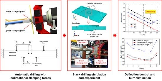
Modeling and Optimization of Bidirectional Clamping Forces in Drilling of Stacked Aluminum Alloy Plates


Abstract
1. Introduction
2. Analytical Modeling and Optimization of Bidirectional Clamping Force
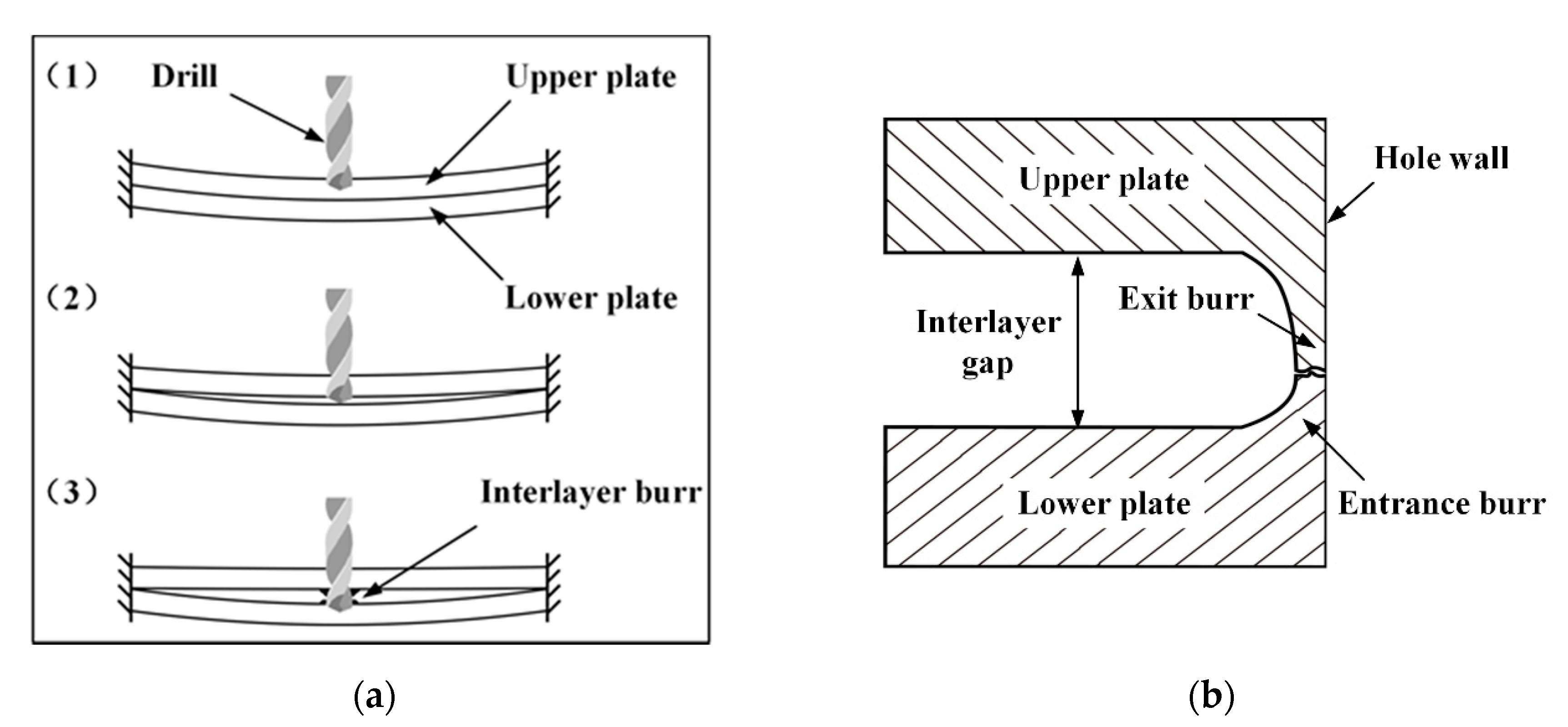
2.1. Modeling of the Interlayer Gap with Bidirectional Clamping Forces
- The stacked plates are both thin plates, with the length and thickness ratio larger than 0.5;
- Only elastic deformation and small deflection occur to the plates, the maximum deflection does not exceed 1/5 of plate thickness.
- The edges of the plates are considered as built-in or fixed.
2.2. Optimization of Two-Side Clamping Force
- Stage1: When the lower clamping force , the one-sided clamping force is adopted. The upper clamping force is the largest among all groups of bidirectional clamping forces at this stage. The deflection of the lower plate is induced by the drilling thrust force , while the upper plate deforms downward due to the upper clamping force until the interlayer gap is eliminated. At this stage, the deflection of the upper plate is more significant than the lower plate , and their difference is equal to the initial gap .
- Stage2: As increases, the deflections of both plates decrease until the effect of counteracts the effect of the drilling force on the lower plate. At the end of stage 2, the deflection of the upper plate is equal to the initial gap while the deflection of the lower plate is zero.
- Stage3: When is greater than the drilling thrust force , the lower plate begins to deform upward, and the downward deformation of the upper plate decreases accordingly. In this stage, the sum of the deflections of the two stacked plates is always equal to the initial gap . When the deflections of the upper and lower plates are the same (), the non-uniformity of the deformation is the smallest. The bidirectional clamping forces at this time can be considered as optimal.
- Stage4: As continues to increase, finally reaches zero. At this moment, the deflection of the upper plate is zero, the lower clamping force is the maximum, and the deflection of the lower plate is equal to the initial gap.
3. Numerical Study
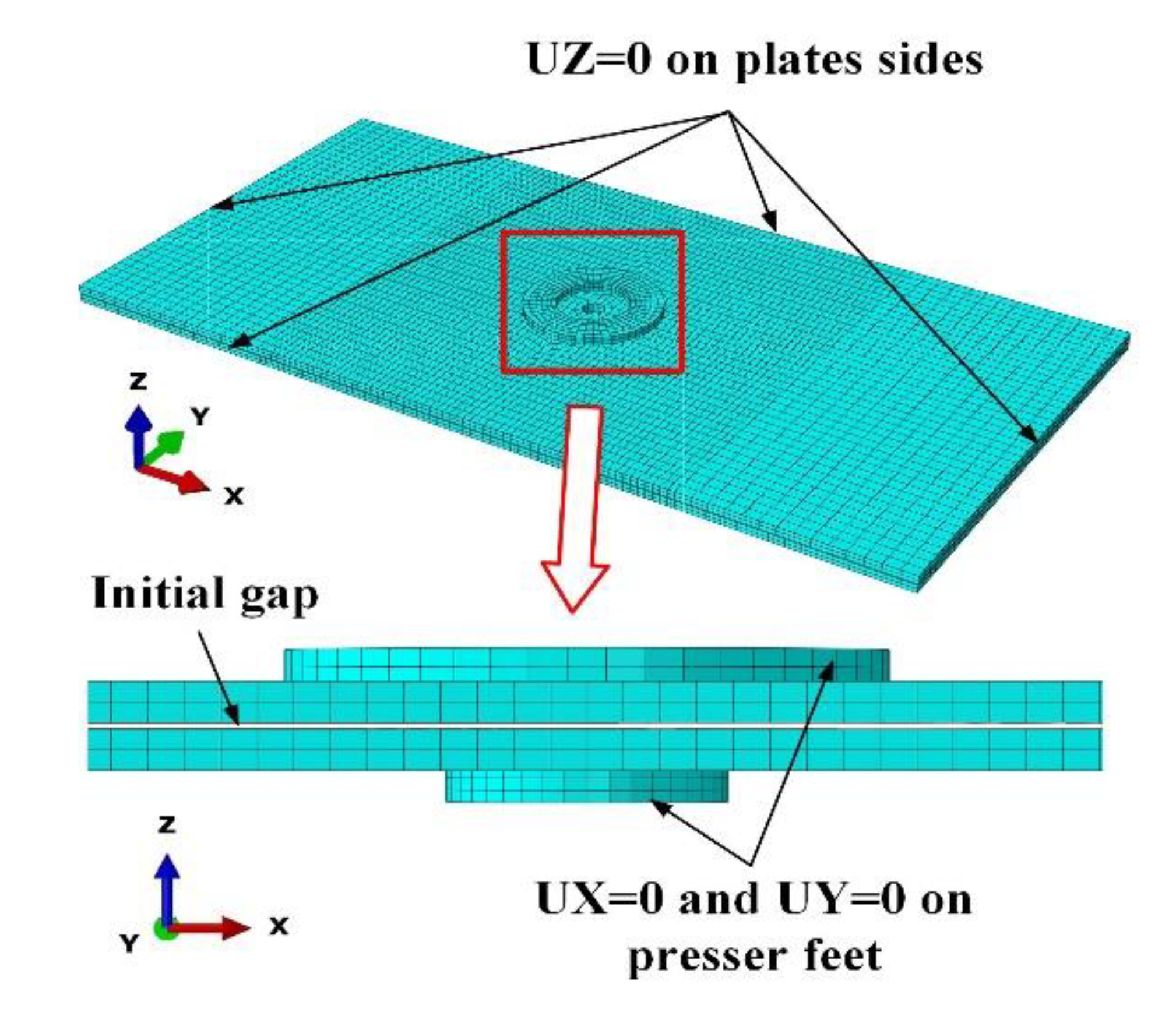
3.1. Finite Element Modeling of Drilling Stacked Plates
- (1)
- Geometric model
- (2)
- Material definition
- (3)
- Mesh selection
- (4)
- Load and boundary condition
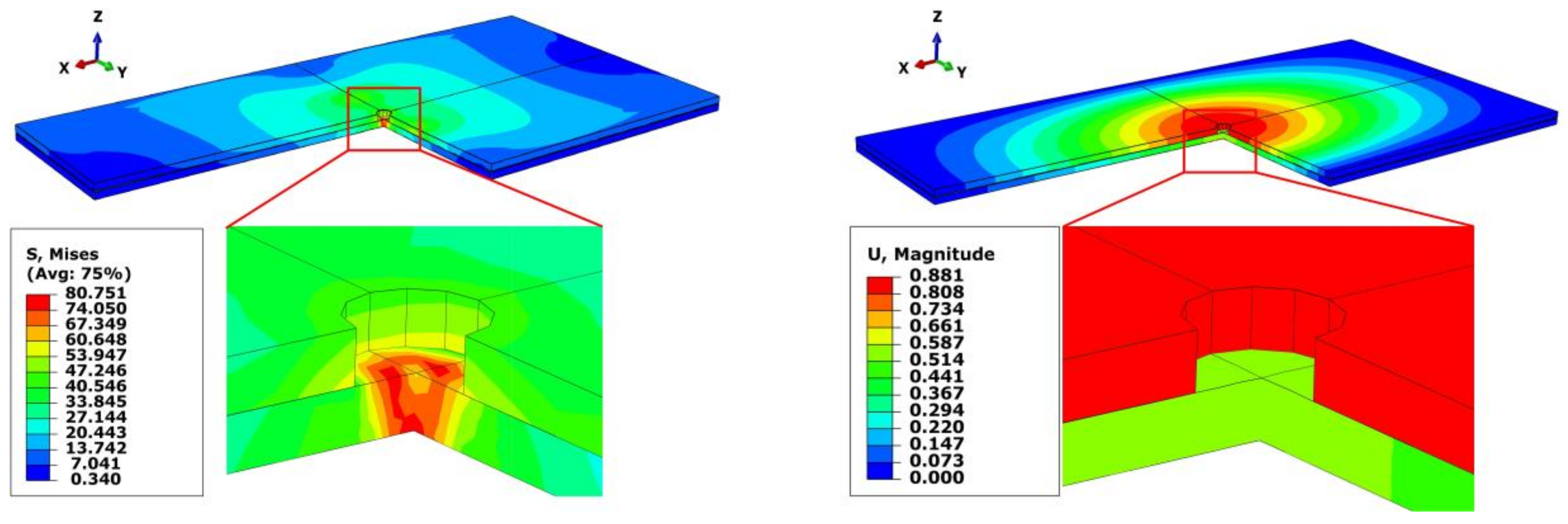
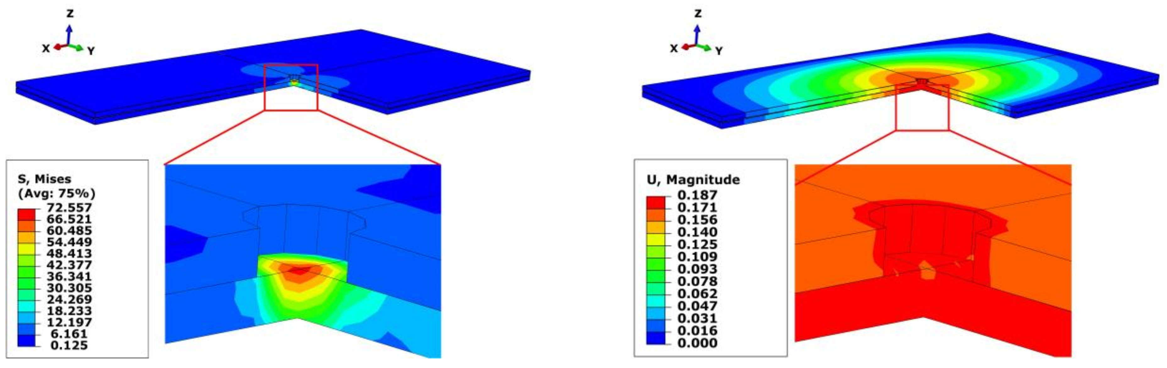
3.2. Simulation Results and Discussion
4. Experiments
4.1. Experimental Setups
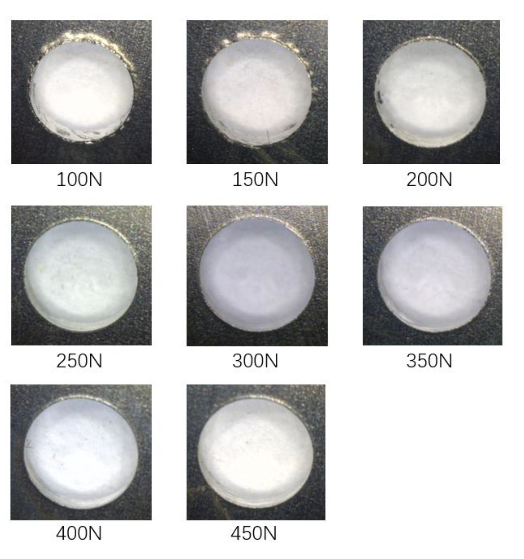
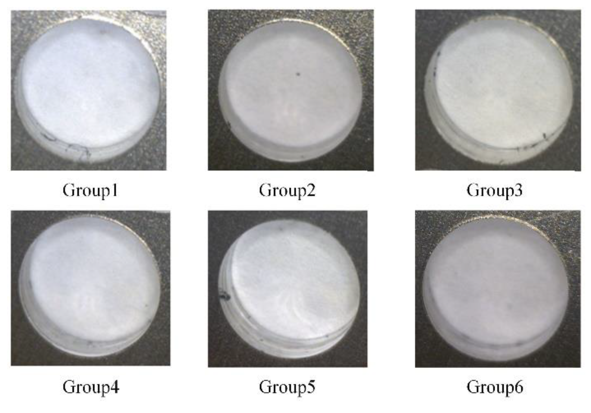
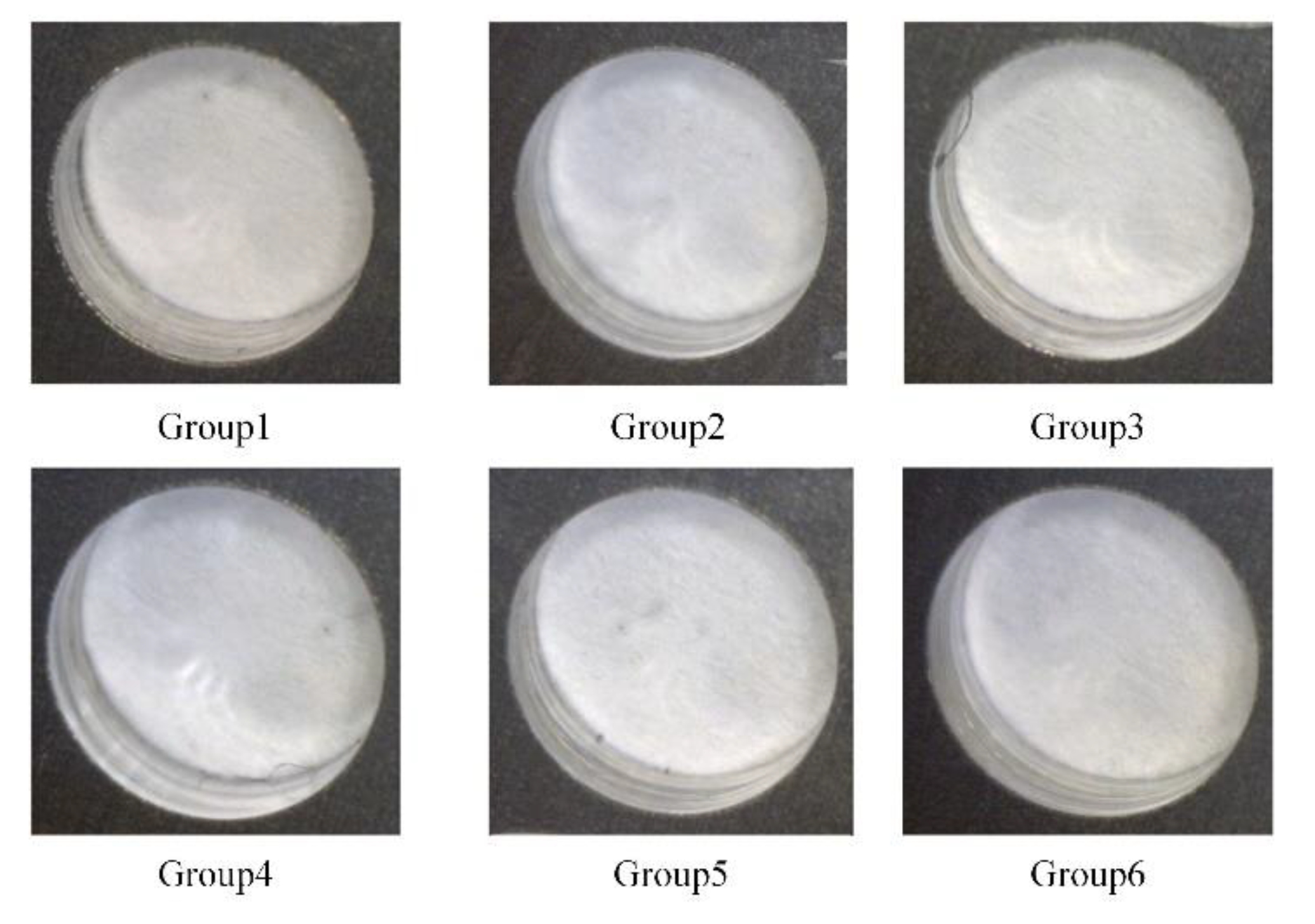
4.2. Experimental Results and Discussion
5. Conclusions
- (1)
- Preloading clamping force can effectively reduce the interlayer gap, thereby eliminate the formation of interlayer burr, and the effect of bidirectional clamping is better than that of one-sided clamping.
- (2)
- Based on the theory of plates and shells, the interlayer gap theoretical model is established. The relationship between the upper and lower clamping forces is derived to ensure the interlayer gap is zero. Under the processing conditions in this paper, their relationship formula is .
- (3)
- When the interlayer gap is zero, four different stages of the stacked plates deflections are revealed based on the interlayer gap theoretical model. Moreover, when the deflection of the upper and lower plates is equal to half of the initial gap, the total deformation of the stacked plates is the smallest, and neither plate will have excessive deflection.
Author Contributions
Funding
Conflicts of Interest
Nomenclature
| The drilling thrust force | |
| and | The pressures applied on the clamping areas of upper side and lower side |
| , , , and | The inner radius and outer radius of the upper and lower presser feet |
| The upper clamping force at circle with radius | |
| The lower clamping force at circle with radius | |
| The initial gap | |
| The interlayer gap | |
| a | The length of the sheet; |
| b | The width of the sheet |
| h | The thickness of the sheet |
| The deflection at the circle of radius caused by unit force at drilling center | |
| The deflection at the circle of radius caused by unit force at upper clamping area | |
| The deflection at the circle of radius caused by unit force at lower clamping area | |
| The deflection at the circle of radius of upper plate | |
| The deflection of the plate caused by the thrust force | |
| The deflection of the lower plate caused by the lower clamping force | |
| The interlayer gap | |
| The deformation of the upper plate | |
| The deformation of the lower plate | |
| The deflection of the rectangular thin plate | |
| A point on the plate | |
| The position of the drilling thrust force applied at the lower plate | |
| and | The positions of the upper and lower clamping forces applied on the plates |
References
- Xu, J.; El Mansori, M. Experimental study on drilling mechanisms and strategies of hybrid CFRP/Ti stacks. Compos. Struct. 2016, 157, 461–482. [Google Scholar] [CrossRef]
- Zitoune, R.; Krishnaraj, V.; Collombet, F. Study of drilling of composite material and aluminium stack. Compos. Struct. 2010, 92, 1246–1255. [Google Scholar] [CrossRef]
- Fernández-Pérez, J.; Cantero, J.L.; Díaz-Álvarez, J.; Miguélez, M.H. Hybrid Composite-Metal Stack Drilling with Different Minimum Quantity Lubrication Levels. Materials 2019, 12, 448. [Google Scholar] [CrossRef]
- Zhu, W.; Qu, W.; Cao, L.; Yang, D.; Ke, Y. An off-line programming system for robotic drilling in aerospace manufacturing. Int. J. Adv. Manuf. Technol. 2013, 68, 2535–2545. [Google Scholar] [CrossRef]
- Tian, W.; Zhou, W.; Zhou, W.; Liao, W.; Zeng, Y. Auto-normalization algorithm for robotic precision drilling system in aircraft component assembly. Chin. J. Aeronaut. 2013, 26, 495–500. [Google Scholar] [CrossRef]
- Bi, S.; Liang, J. Robotic drilling system for titanium structures. Int. J. Adv. Manuf. Technol. 2011, 54, 767–774. [Google Scholar] [CrossRef]
- Shyha, I.S.; Soo, S.L.; Aspinwall, D.K.; Bradley, S.; Perry, R.; Harden, P.; Dawson, S. Hole quality assessment following drilling of metallic-composite stacks. Int. J. Mach. Tools Manuf. 2011, 51, 569–578. [Google Scholar] [CrossRef]
- Aurich, J.C.; Dornfeld, D.; Arrazola, P.J.; Franke, V.; Leitz, L.; Min, S. Burrs—Analysis, control and removal. CIRP Ann. 2009, 58, 519–542. [Google Scholar] [CrossRef]
- Pilný, L.; De Chiffre, L.; Piska, M.; Villumsen, M.F. Hole quality and burr reduction in drilling aluminium sheets. CIRP J. Manuf. Sci. Technol. 2012, 5, 102–107. [Google Scholar] [CrossRef]
- Bi, S.; Liang, J. Experimental studies and optimization of process parameters for burrs in dry drilling of stacked metal materials. Int. J. Adv. Manuf. Technol. 2011, 53, 867–876. [Google Scholar] [CrossRef]
- Krishnaraj, V.; Zitoune, R.; Collombet, F. Comprehensive review on drilling of multimaterial stacks. J. Mach. Form. Technol. 2010, 2, 1–32. [Google Scholar]
- Tian, W.; Hu, J.; Liao, W.; Bu, Y.; Zhang, L. Formation of interlayer gap and control of interlayer burr in dry drilling of stacked aluminum alloy plates. Chin. J. Aeronaut. 2016, 29, 283–291. [Google Scholar] [CrossRef]
- Abdelhafeez, A.; Soo, S.L.; Aspinwall, D.; Dowson, A.; Arnold, D. Burr Formation and Hole Quality when Drilling Titanium and Aluminium Alloys. Procedia CIRP 2015, 37, 230–235. [Google Scholar] [CrossRef]
- Hellstern, C. Investigation of Interlayer Burr Formation in the Drilling of Stacked Aluminum Sheets. Ph.D. Thesis, Georgia Institute of Technology, Georgia, GA, USA, 2009. [Google Scholar]
- Abdelhafeez, A.M.; Soo, S.L.; Aspinwall, D.K.; Dowson, A.; Arnold, D. The influence of burr formation and feed rate on the fatigue life of drilled titanium and aluminium alloys used in aircraft manufacture. CIRP Ann. 2018, 67, 103–108. [Google Scholar] [CrossRef]
- Hu, Y.; Song, Y.; Li, Y.; Yao, Z. An analytical model to predict interfacial burr height for metal stack drilling. Proc. Inst. Mech. Eng. Part B: J. Eng. Manuf. 2017, 233, 99–108. [Google Scholar] [CrossRef]
- Hassan, A.A.; Soo, S.L.; Aspinwall, D.K.; Arnold, D.; Dowson, A. An analytical model to predict interlayer burr size following drilling of CFRP-metallic stack assemblies. CIRP Ann. 2020. [Google Scholar] [CrossRef]
- Rodríguez-Barrero, S.; Fernández-Larrinoa, J.; Azkona, I.; De Lacalle, L.N.L.; Polvorosa, R. Enhanced Performance of Nanostructured Coatings for Drilling by Droplet Elimination. Mater. Manuf. Process. 2014, 31, 1–10. [Google Scholar] [CrossRef]
- Abia, A.I.F.; Barreiro, J.; Fernández-Larrinoa, J.; Fernández-Valdivielso, A.; Pereira, O.; De Lacalle, L.N.L. Behaviour of PVD Coatings in the Turning of Austenitic Stainless Steels ? Procedia Eng. 2013, 63, 133–141. [Google Scholar] [CrossRef]
- Liang, J. The formation and effect of interlayer gap in dry drilling of stacked metal materials. Int. J. Adv. Manuf. Technol. 2013, 69, 1263–1272. [Google Scholar] [CrossRef]
- Li, Y.; Hu, Y.X.; Yao, Z.Q. Modeling and Analysis of the Effect of Preloaded Pressing Force on Gap Formation during the Drilling of Double-Layered Material. Appl. Mech. Mater. 2012, 217–219, 1541–1546. [Google Scholar] [CrossRef]
- Yin, B.; Wei, T.; WenHe, L.; Jian, H.; Xin, S. Investigation of correlation between interlayer gap and burr height in drilling of stacked Al-7475 materials. Proc. Inst. Mech. Eng. Part B: J. Eng. Manuf. 2017, 231, 1917–1930. [Google Scholar] [CrossRef]
- Gao, Y.; Wu, D.; Nan, C.; Ma, X.; Dong, Y.; Chen, K. The interlayer gap and non-coaxiality in stack drilling. Int. J. Mach. Tools Manuf. 2015, 99, 68–76. [Google Scholar] [CrossRef]
- Melkote, S.N.; Newton, T.R.; Hellstern, C.; Morehouse, J.B.; Turner, S. Interfacial Burr Formation in Drilling of Stacked Aerospace Materials. In Burrs—Analysis, Control and Removal; Aurich, J.C., Dornfeld, D., Eds.; Springer: Berlin/Heidelberg, Germany, 21 October 2010; pp. 89–98. ISBN 978-3-642-00567-1. [Google Scholar]
- Choi, J.; Min, S.; Dornfeld, D.; Alam, M.; Tzong, T. Modeling of Inter-Layer Gap Formation in Drilling of a Multi-Layered Material. In Proceedings of the 6th CIRP International Workshop on Modeling of Machining Operations, Hamilton, ON, Canada, 19–20 May 2003. [Google Scholar]
- Liang, X.; Wu, D.; Gao, Y.; Chen, K. Investigation on the non-coaxiality in the drilling of carbon-fibre-reinforced plastic and aluminium stacks. Int. J. Mach. Tools Manuf. 2018, 125, 1–10. [Google Scholar] [CrossRef]
- Lei, C.; Li, C.; Bi, Y.; Li, J. The optimal clamping force option for robotic drilling of stacked aluminum sheets based on shell theory. Adv. Mech. Eng. 2017, 9. [Google Scholar] [CrossRef]
- Liu, H.; Lin, J.; Cao, M. Shell Theory; Zhejiang University Press: Hangzhou, China, 1987; pp. 161–210. [Google Scholar]
- Segonds, S.; Masounave, J.; Songmene, V.; Bès, C. A simple analytical model for burr type prediction in drilling of ductile materials. J. Mater. Process. Technol. 2013, 213, 971–977. [Google Scholar] [CrossRef]


| Component | Material | Elastic Modulus/GPa | Poisson’s Ratio |
|---|---|---|---|
| Plate | 2024-T3 aluminum alloy | 72 | 0.34 |
| Presser foot | Stainless steel | 200 | 0.3 |
| Drill | Cemented carbide | - | 0.3 |
| Component | Parameter | Value |
|---|---|---|
| Plate | Length (a) | 200 |
| Width (b) | 100 | |
| Thickness (h) | 2 | |
| Upper presser foot | Inner radius () | 8 |
| Outer radius () | 15 | |
| Lower presser foot | Inner radius () | 5 |
| Outer radius () | 7 |
| r/(mm) | |||
|---|---|---|---|
| 0 | 3.0594 | 2.7865 | 2.9770 |
| 2 | 3.0518 | 2.7828 | 2.9711 |
| 4 | 3.0294 | 2.7719 | 2.9537 |
| 6 | 2.9939 | 2.7535 | 2.9255 |
| 8 | 2.9475 | 2.7276 | 2.8872 |
| 10 | 2.8927 | 2.6941 | 2.8404 |
| 12 | 2.8318 | 2.6536 | 2.7866 |
| 14 | 2.7673 | 2.6064 | 2.7274 |
| 20 | 2.5288 | 2.5603 | 2.4350 |
| 30 | 2.1615 | 2.1843 | 2.0972 |
| Group | Remark | ||
|---|---|---|---|
| 1 | 268.3 | 0 | One-sided clamping |
| 2 | 214.9 | 50 | - |
| 3 | 161.5 | 100 | - |
| 4 | 108.1 | 150 | - |
| 5 | 62.9 | 192.3 | Optimal bidirectional clamping |
| 6 | 0 | 251.2 | One-sided clamping |
| Group | Deflection Index T in Equation (16) | |||
|---|---|---|---|---|
| 1 | 0.0008 | 0.8806 | 0.5298 | 0.7052 |
| 2 | 0.0008 | 0.7004 | 0.3496 | 0.5250 |
| 3 | −0.0001 | 0.5151 | 0.1652 | 0.3402 |
| 4 | −0.0005 | 0.3281 | −0.0224 | 0.1529 |
| 5 | 0.0005 | 0.1722 | −0.1784 | 0.0031 |
| 6 | 0.0013 | −0.0205 | −0.3706 | 0.1955 |
© 2020 by the authors. Licensee MDPI, Basel, Switzerland. This article is an open access article distributed under the terms and conditions of the Creative Commons Attribution (CC BY) license (http://creativecommons.org/licenses/by/4.0/).
Share and Cite
Liu, J.; Zhao, A.; Wan, P.; Dong, H.; Bi, Y. Modeling and Optimization of Bidirectional Clamping Forces in Drilling of Stacked Aluminum Alloy Plates. Materials 2020, 13, 2866. https://doi.org/10.3390/ma13122866
Liu J, Zhao A, Wan P, Dong H, Bi Y. Modeling and Optimization of Bidirectional Clamping Forces in Drilling of Stacked Aluminum Alloy Plates. Materials. 2020; 13(12):2866. https://doi.org/10.3390/ma13122866
Chicago/Turabian StyleLiu, Jintong, Anan Zhao, Piao Wan, Huiyue Dong, and Yunbo Bi. 2020. "Modeling and Optimization of Bidirectional Clamping Forces in Drilling of Stacked Aluminum Alloy Plates" Materials 13, no. 12: 2866. https://doi.org/10.3390/ma13122866
APA StyleLiu, J., Zhao, A., Wan, P., Dong, H., & Bi, Y. (2020). Modeling and Optimization of Bidirectional Clamping Forces in Drilling of Stacked Aluminum Alloy Plates. Materials, 13(12), 2866. https://doi.org/10.3390/ma13122866