Study on Microstructural and Mechanical Properties of an Al–Cu–Sn Alloy Wall Deposited by Double-Wire Arc Additive Manufacturing Process


Abstract
:1. Introduction
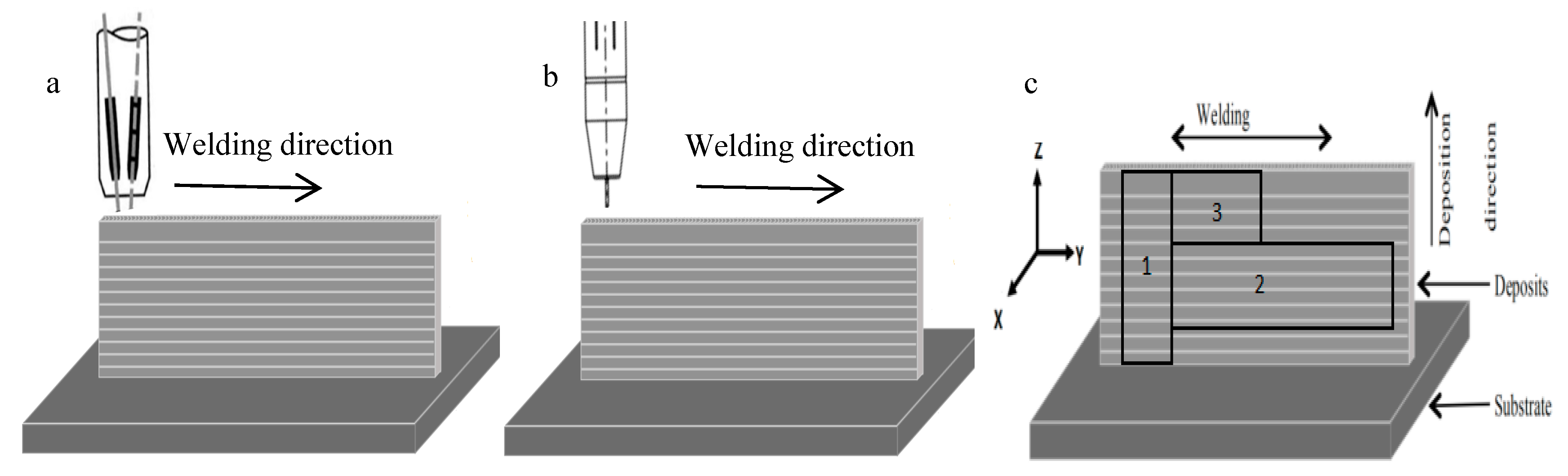
2. Experimental
Materials and Methods
3. Results and Discussion
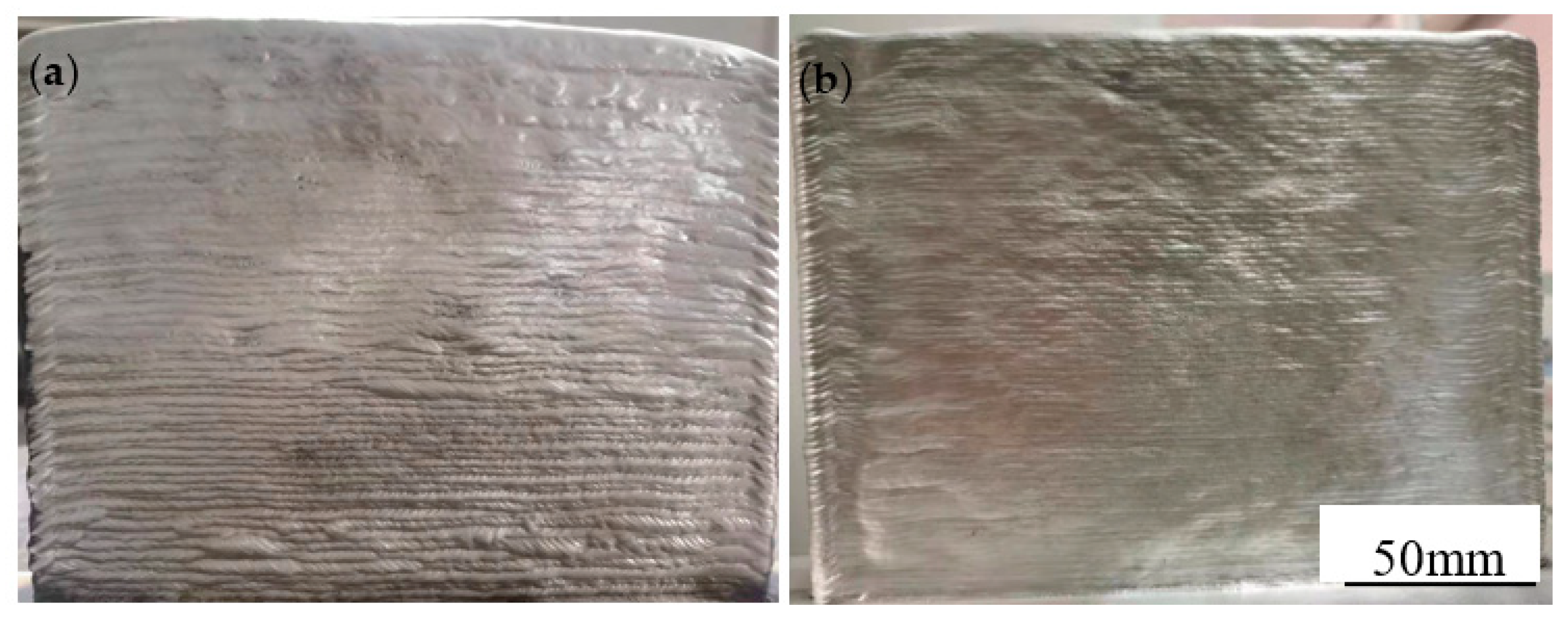
3.1. Surface Morphology of Walls
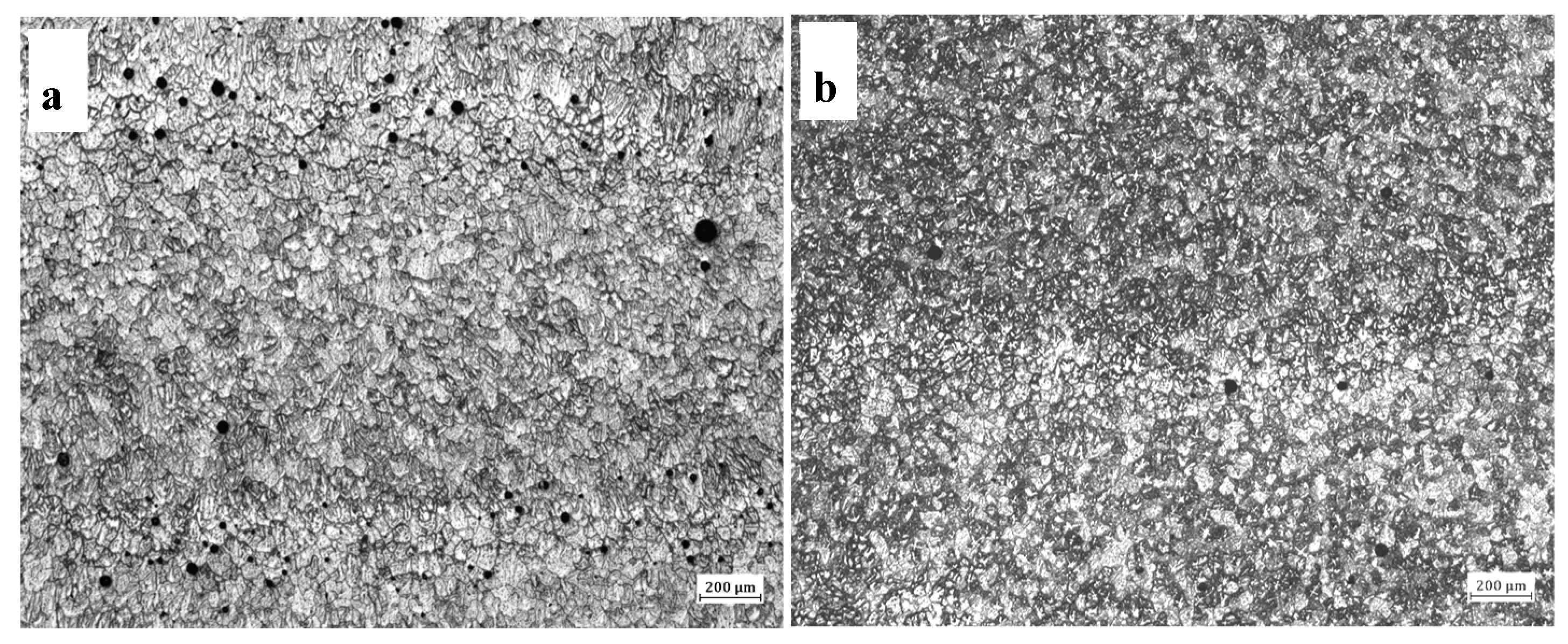
3.2. Porosity of Walls
3.3. Microstructure of Walls
3.3.1. Microstructure of Walls in As-Deposited State
3.3.2. Microstructure of Walls in T6 State
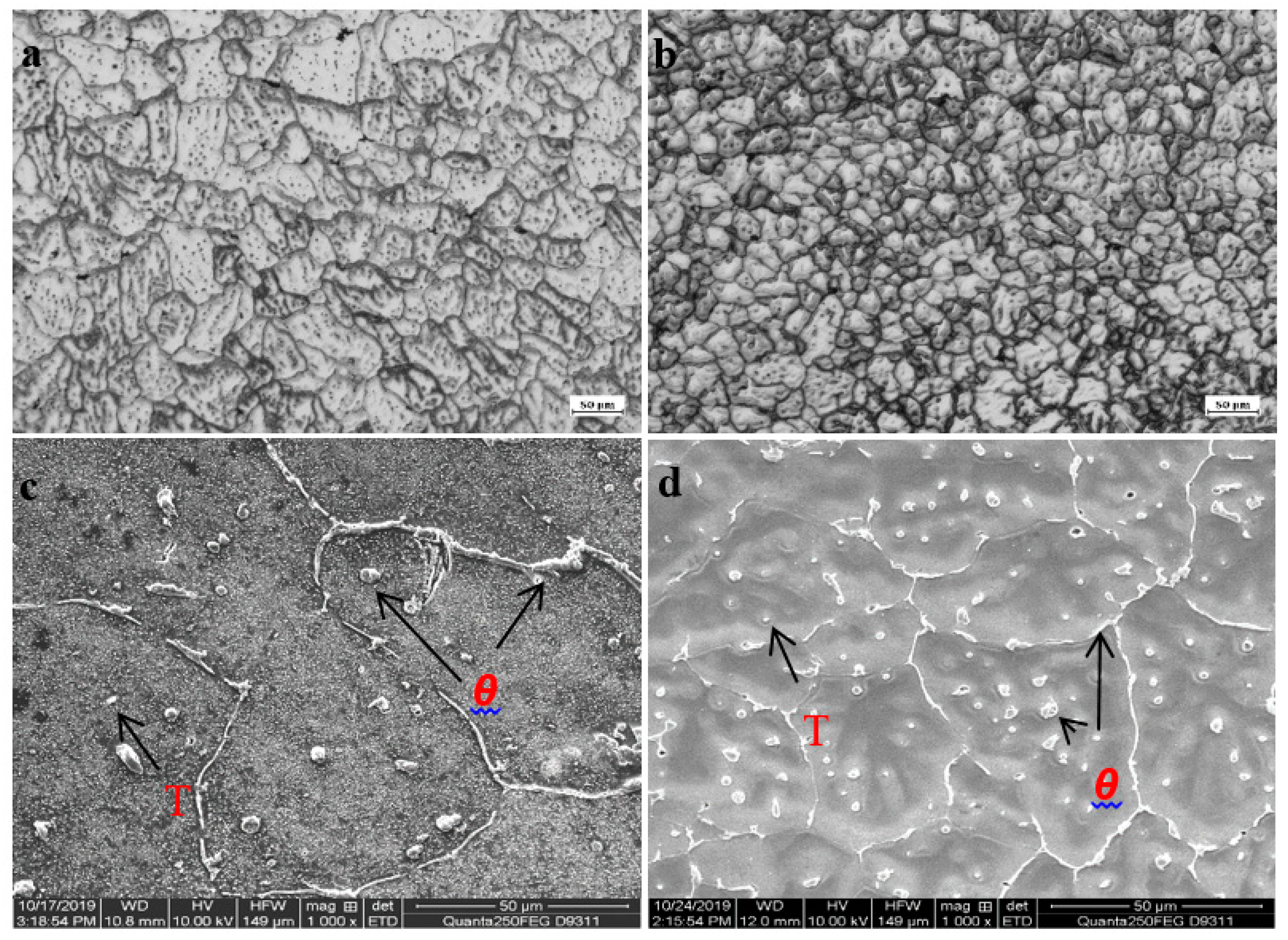
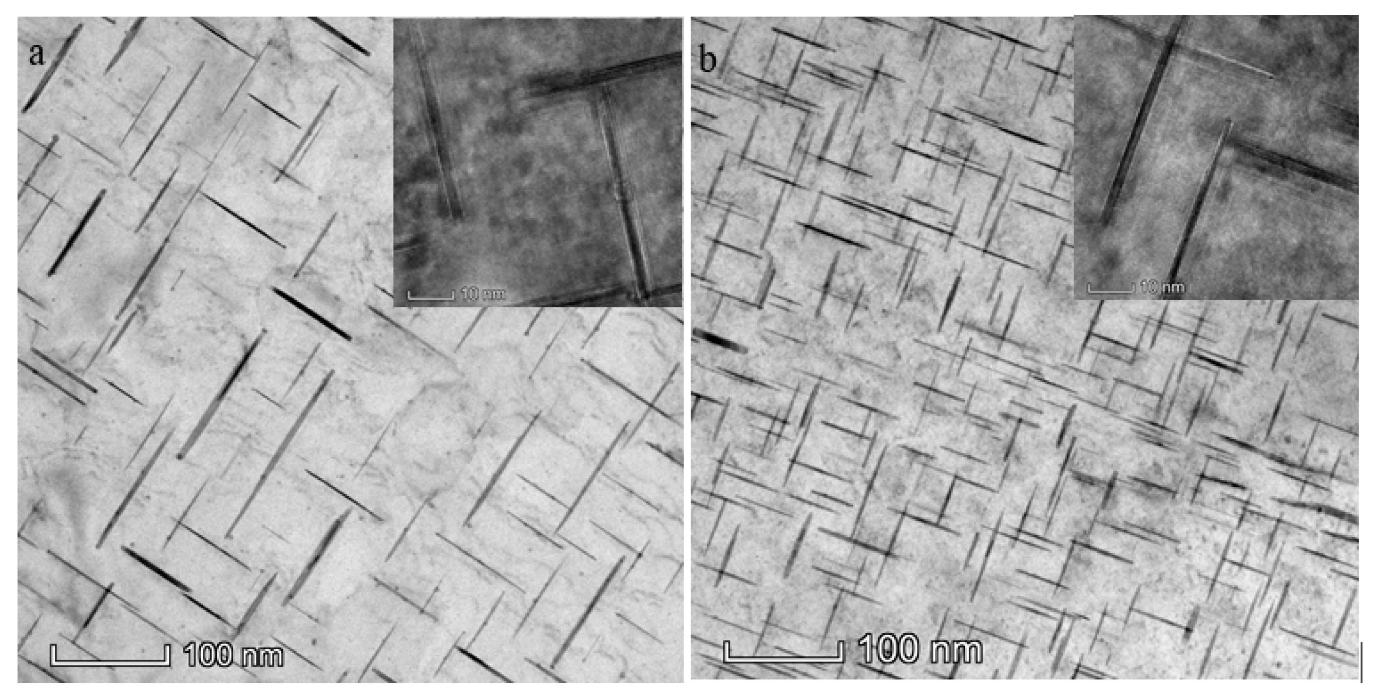
3.3.3. Strengthening Phase at Peak Aging
3.4. Mechanical Properties and Fracture Morphology of Walls
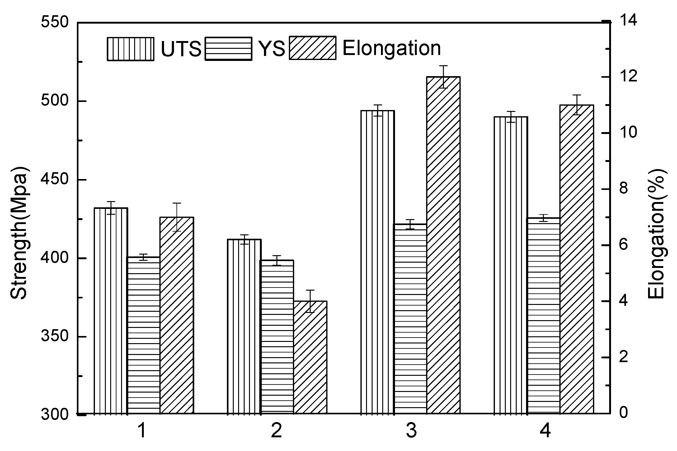
3.4.1. Mechanical Properties of Walls
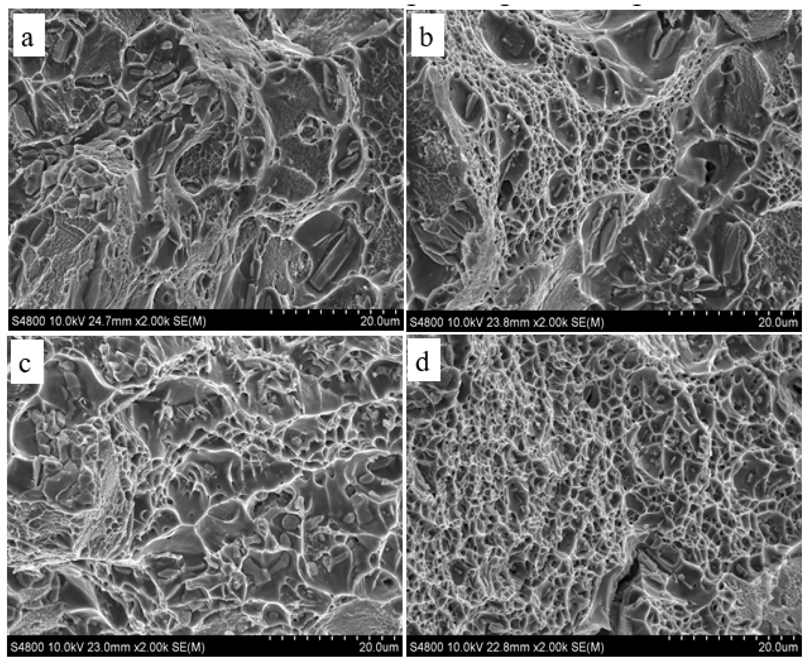
3.4.2. Fracture Morphology of Walls
4. Conclusions
- (1)
- At the same wire feeding speed, the heat input of the double-wire process was half that of the single wire, the surface quality of the double-wire wall improved, and accumulation efficiency also improved.
- (2)
- The number of pores in the double-wire wall was much smaller than that of the single-wire wall. The grains were mainly fine isometric crystals of uniform size, and the precipitated phases were diffusely distributed in the grain and on the grain boundary in the as-deposited state.
- (3)
- After T6 heat treatment, the θ phases of the double-wire wall dissolved into the matrix completely, and the number of θ’ phases was larger than the single-wire wall.
- (4)
- The tensile strength, yield strength, and elongation were 490 MPa, 420 MPa, and 12%, respectively, with no difference between the longitudinal and transverse. The fracture mode was a ductile fracture.
Author Contributions
Funding
Acknowledgments
Conflicts of Interest
References
- Liu, J.; Kulak, M. A new paradigm in the design of aluminum alloys for aerospace applications. Mater. Sci. Forum 2000, 331–337, 127–142. [Google Scholar] [CrossRef]
- Rooy, E.L. Metals Handbook; ASM International: Novelty, OH, USA, 1988; Volume 15, pp. 743–770. [Google Scholar]
- Lee, J.; Park, J.; Jeong, H. Effect of strain on mechanical and microstructural properties of Al/Cu claddings during caliber-rolling. Mater. Lett. 2018, 222, 122–125. [Google Scholar] [CrossRef]
- Cong, B.; Ding, J. Influence of CMT Process on Porosity of Wire Arc Additive Manufactured Al-Cu Alloy. Rare Met. Mater. Eng. 2018, 12, 3149–3153. [Google Scholar]
- Gu, J.L. Study on Microstructure and Mechanical Properties of Additively Manufactured Al-Cu-(Mg) Alloys with the CMT Process; Northeastern University: Shenyang, China, 2016. [Google Scholar]
- Wang, S.; Gu, H.; Wang, W.; Li, C.; Ren, L.; Wang, Z.; Zhai, Y.; Ma, P. Microstructure and Mechanical Properties of aluminum alloy (ZL205A) wall produced by wire arc additive manufacturing method. Rare Met. Mater. Eng. 2019, 9, 2910–2916. [Google Scholar]
- Qi, Z.; Cong, B.; Qi, B.; Zhao, G.; Ding, J. Properties of wire + arc additively manufactured 2024 aluminum alloy with different solution treatment temperature. Mater. Lett. 2018, 230, 275–278. [Google Scholar] [CrossRef] [Green Version]
- Fronius Sales Brochure. Time Twin Mig/Mag Tandem Welding [DB/OL]. Available online: www.Fronius.com (accessed on 15 January 2018).
- Liu, P.; Han, S. Microstructure Analysis of Q690 High Strength Steel Double Wire CMT Welded Joint. Hot Work. Technol. 2018, 21, 250–253. [Google Scholar]
- Han, S.; Zheng, S. Effect of CMT-Twin Welding Parameters on Mechanical Properties and Microstructure of 1561 Aluminum Alloy Welded Joint. Weld. Join. 2017, 5, 31–34. [Google Scholar]
- Hua, G.; Ahmadi, H.; Nouri, M.; Li, D. Positive effect of yttrium on the reduction of pores in cast Al alloy. Mater. Chem. Phys. 2015, 149–150, 140–144. [Google Scholar] [CrossRef]
- Ferrie, E.; Buffiere, J.; Ludwig, W. 3D characterisation of the nucleation of a short fatigue crack at a pore in a cast Al alloy using high resolution synchrotron microtomography. Int. J. Fatigue 2005, 27, 1215–1220. [Google Scholar] [CrossRef]
- Cook, G.E.; Eassa, E.H. The Effect of High-Frequency Pulsing of a Welding Arc. IEEE Trans. Ind. Appl. 1985, 1A-21, 1294–1299. [Google Scholar] [CrossRef]
- Cong, B.; Ouyang, R.; Qi, B.; Ding, J. Influence of Cold Metal Transfer Process and Its Heat Input on Weld Bead Geometry and Porosity of Aluminum-Copper Alloy Welds. Rare Met. Mater. Eng. 2016, 45, 606–611. [Google Scholar] [CrossRef]
- Fujii, H.; Nogi, K. Formation and disappearance of pores in aluminum alloy molten pool under microgravity. Sci. Technol. Adv. Mater. 2004, 5, 219–223. [Google Scholar] [CrossRef]
- Lin, R.Y.; Fan, J. Solubility of hydrogen in aluminum alloy melt. Light Alloy Fabr. Technol. 1991, 4, 17–20. [Google Scholar]
- Zhang, W. Metal Fusion Welding Principle and Technology; Machinery Industry Press: Beijing, China, 1983; pp. 160–169. [Google Scholar]
- Hall, M.G.; Haworth, C.W. Dissolution of θ phase in Al-5% Cu. Acta Metall. 1970, 3, 331–337. [Google Scholar] [CrossRef]
- Banerjee, S.; Robi, P.S.; Srinivasan, A.; Lakavath, P.K. Effect of trace additions of Sn on microstructure and mechanical properties of Al–Cu–Mg alloys. Mater. Des. 2010, 31, 4007–4015. [Google Scholar] [CrossRef]
- Badin, C.; Marino, F.; Verne, E. Calorimetric study on precipitation path in 2024 alloy and its SiC composite. Mater. Sci. Eng. A 1995, 191, 185–191. [Google Scholar] [CrossRef]


| Element | Fe | Si | Mg | Cu | Mn | Ti | Sn | Zr | B | V |
|---|---|---|---|---|---|---|---|---|---|---|
| Content (wt %) | 0.100 | 0.040 | 0.025 | 5.102 | 0.421 | 0.272 | 0.103 | 0.177 | 0.034 | 0.125 |
| Parameters | I/A | U/V | νWFS/m·min−1 | νTS/m·min−1 | Cool Time/s |
|---|---|---|---|---|---|
| Single wire | 123 | 17.5 | 6 | 12 | 120 |
| Double wire | 56 + 56 | 14.6 + 14.6 | 3 + 3 | 12 | 120 |
© 2019 by the authors. Licensee MDPI, Basel, Switzerland. This article is an open access article distributed under the terms and conditions of the Creative Commons Attribution (CC BY) license (http://creativecommons.org/licenses/by/4.0/).
Share and Cite
Wang, S.; Gu, H.; Wang, W.; Li, C.; Ren, L.; Wang, Z.; Zhai, Y.; Ma, P. Study on Microstructural and Mechanical Properties of an Al–Cu–Sn Alloy Wall Deposited by Double-Wire Arc Additive Manufacturing Process. Materials 2020, 13, 73. https://doi.org/10.3390/ma13010073
Wang S, Gu H, Wang W, Li C, Ren L, Wang Z, Zhai Y, Ma P. Study on Microstructural and Mechanical Properties of an Al–Cu–Sn Alloy Wall Deposited by Double-Wire Arc Additive Manufacturing Process. Materials. 2020; 13(1):73. https://doi.org/10.3390/ma13010073
Chicago/Turabian StyleWang, Shuai, Huimin Gu, Wei Wang, Chengde Li, Lingling Ren, Zhenbiao Wang, Yuchun Zhai, and Peihua Ma. 2020. "Study on Microstructural and Mechanical Properties of an Al–Cu–Sn Alloy Wall Deposited by Double-Wire Arc Additive Manufacturing Process" Materials 13, no. 1: 73. https://doi.org/10.3390/ma13010073
APA StyleWang, S., Gu, H., Wang, W., Li, C., Ren, L., Wang, Z., Zhai, Y., & Ma, P. (2020). Study on Microstructural and Mechanical Properties of an Al–Cu–Sn Alloy Wall Deposited by Double-Wire Arc Additive Manufacturing Process. Materials, 13(1), 73. https://doi.org/10.3390/ma13010073