Perfect Combination of LBL with Sol–Gel Film to Enhance the Anticorrosion Performance on Al Alloy under Simulated and Accelerated Corrosive Environment

 ,
,  ,
,
Abstract

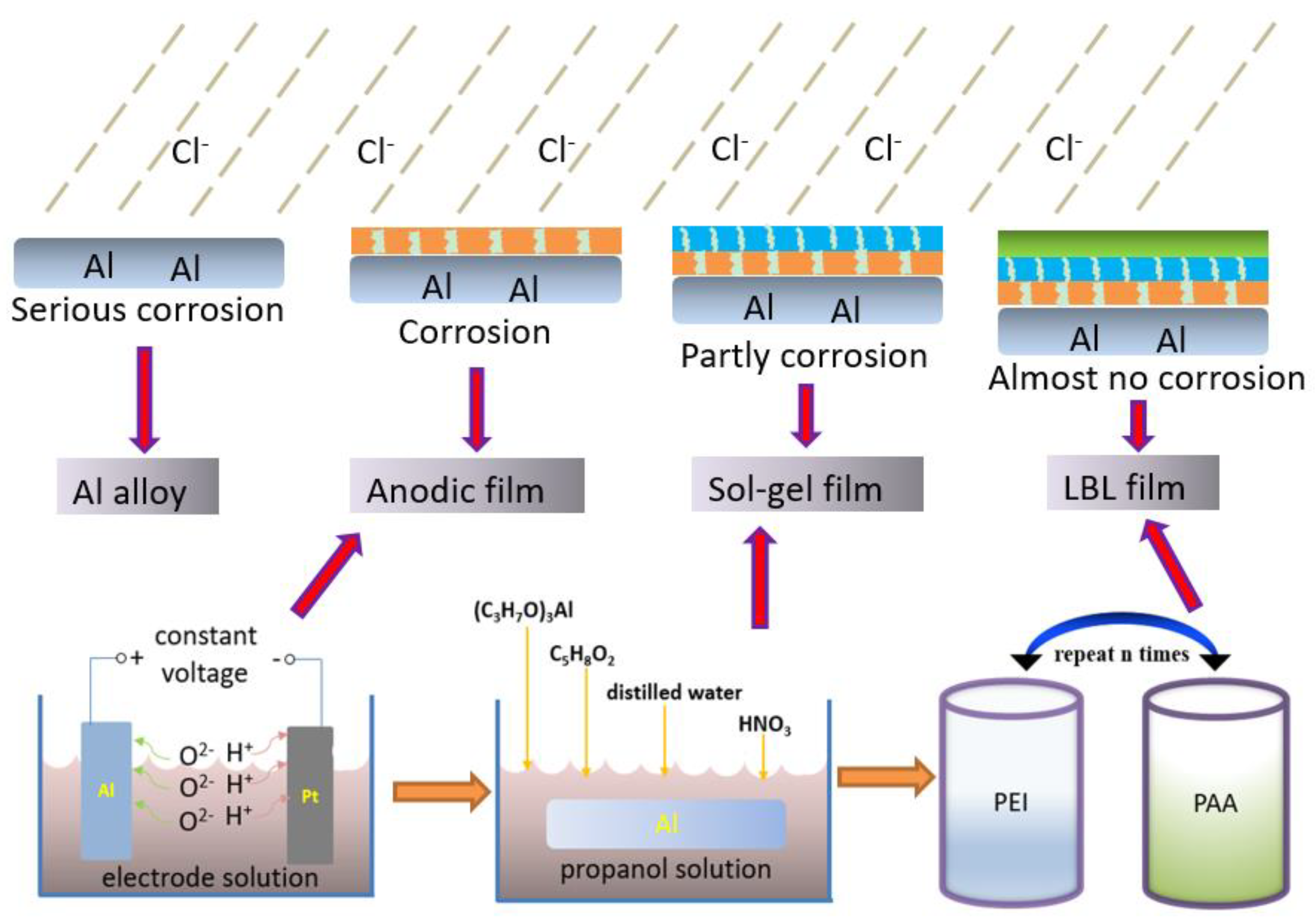
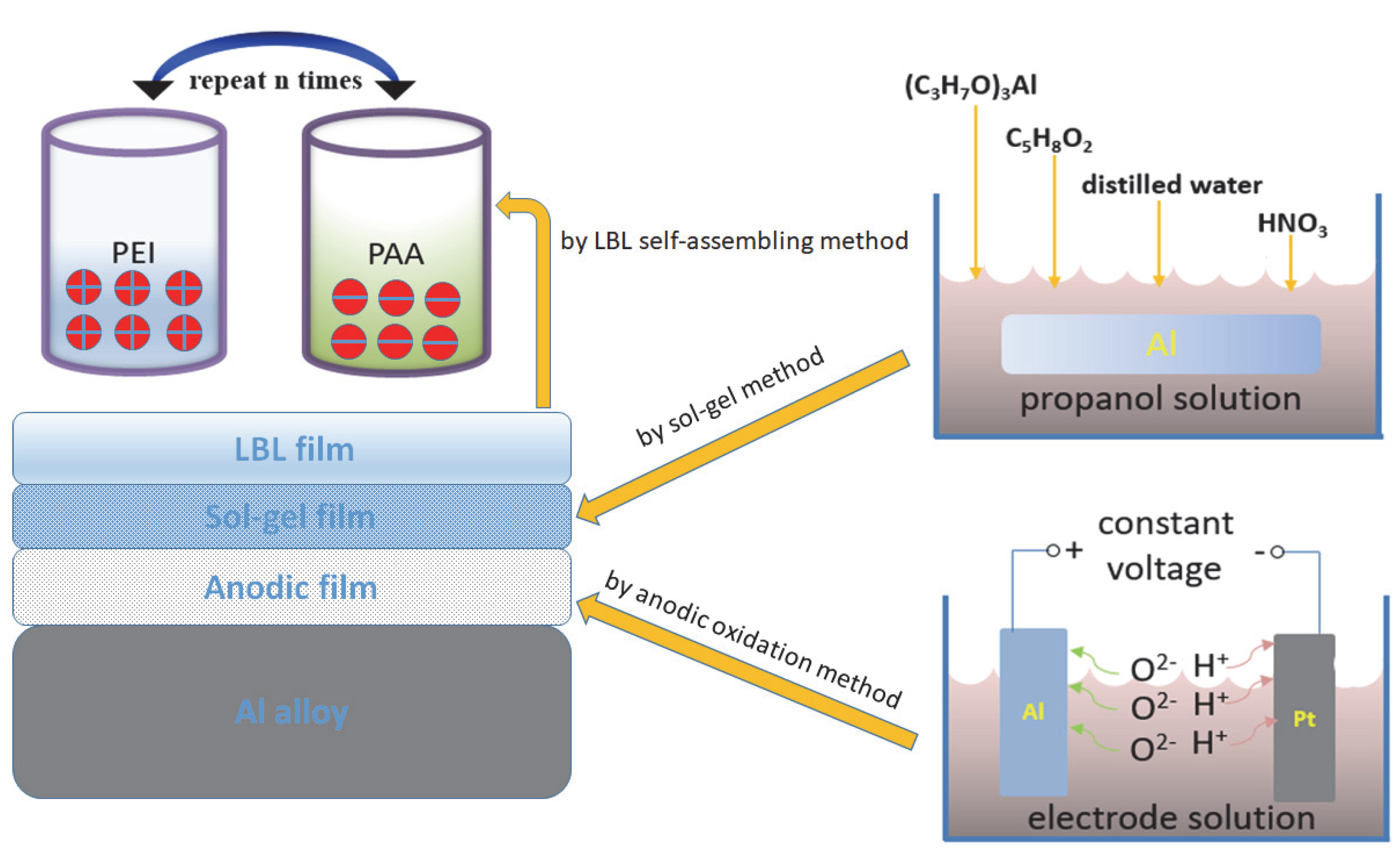
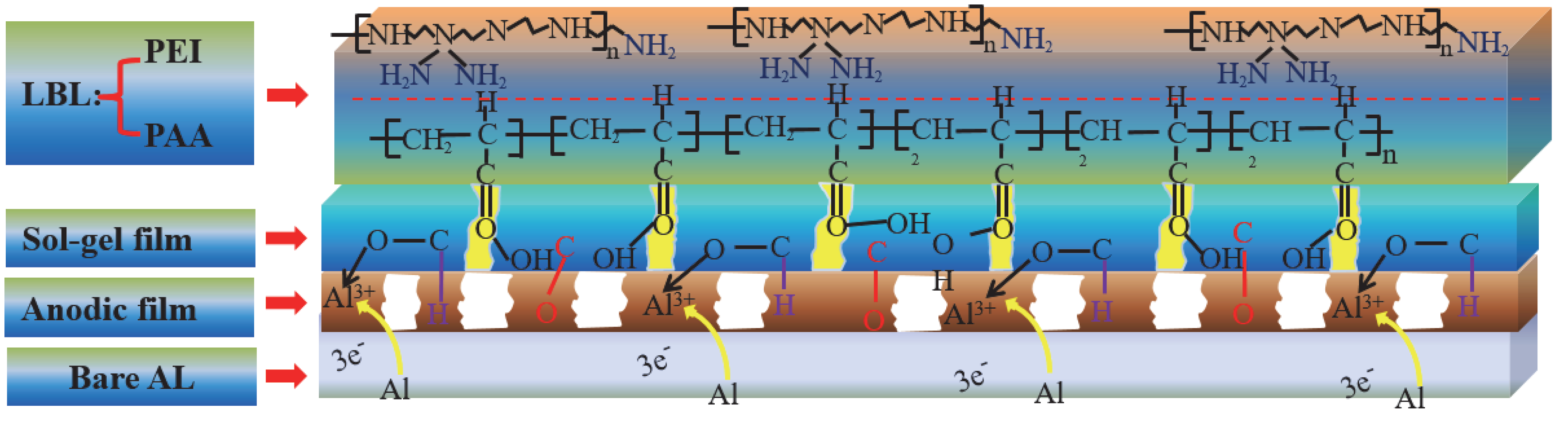
1. Introduction
2. Experimental and Characterization
2.1. Materials and Reagents
2.2. Pretreatment and Preparation of Anodic Oxide Film
2.3. Preparation of the Sol–Gel Film
2.4. Preparation of the LBL Self-Assembled Protective Film
2.5. Methods
2.5.1. Characterization
2.5.2. Electrochemical Measurements
2.5.3. Salt-Spray Test
3. Results and Discussion
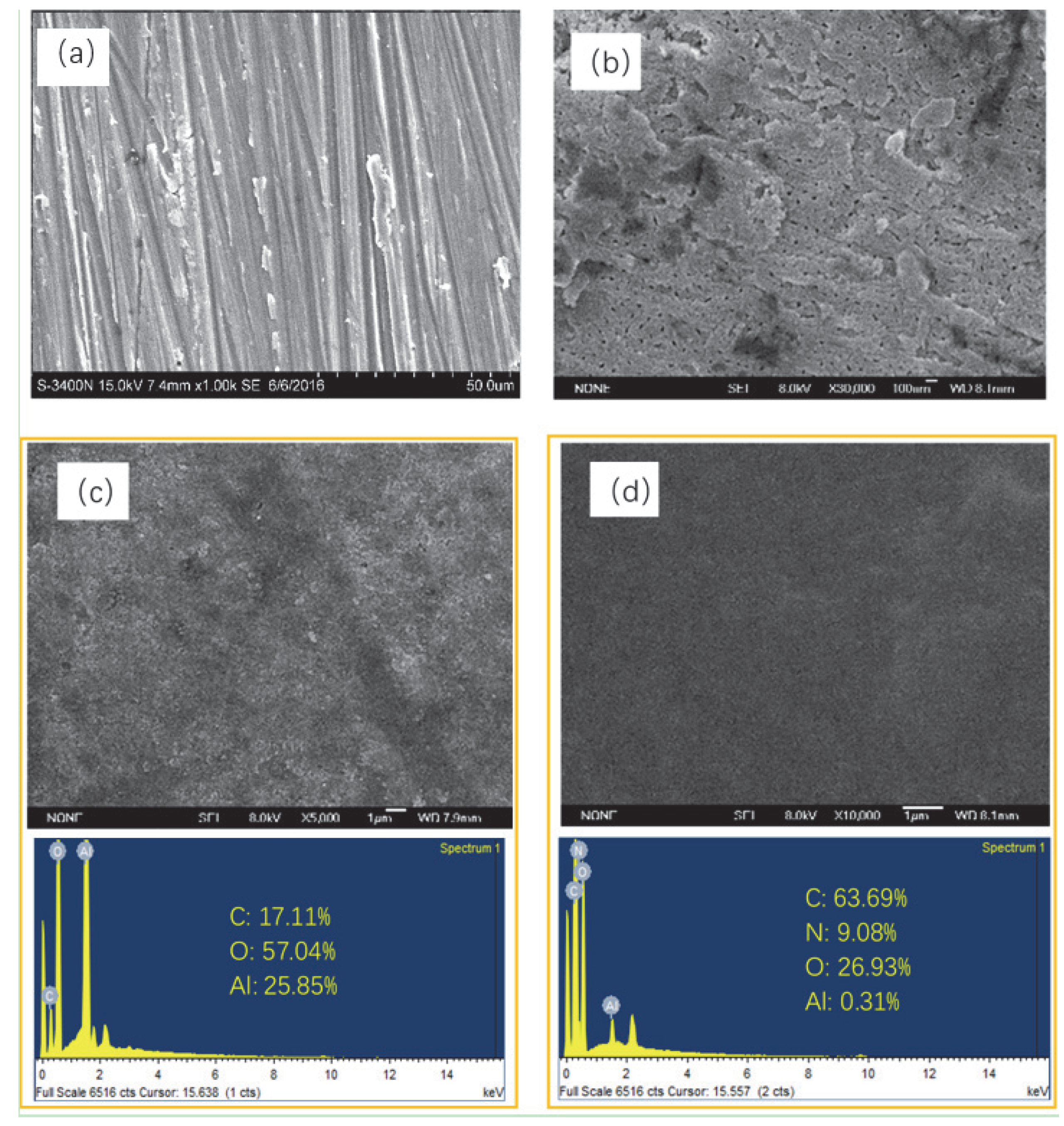
3.1. Surface Morphologies and Composition of the Films
3.2. Chemical Composition of Different Films
3.3. Surface Roughness
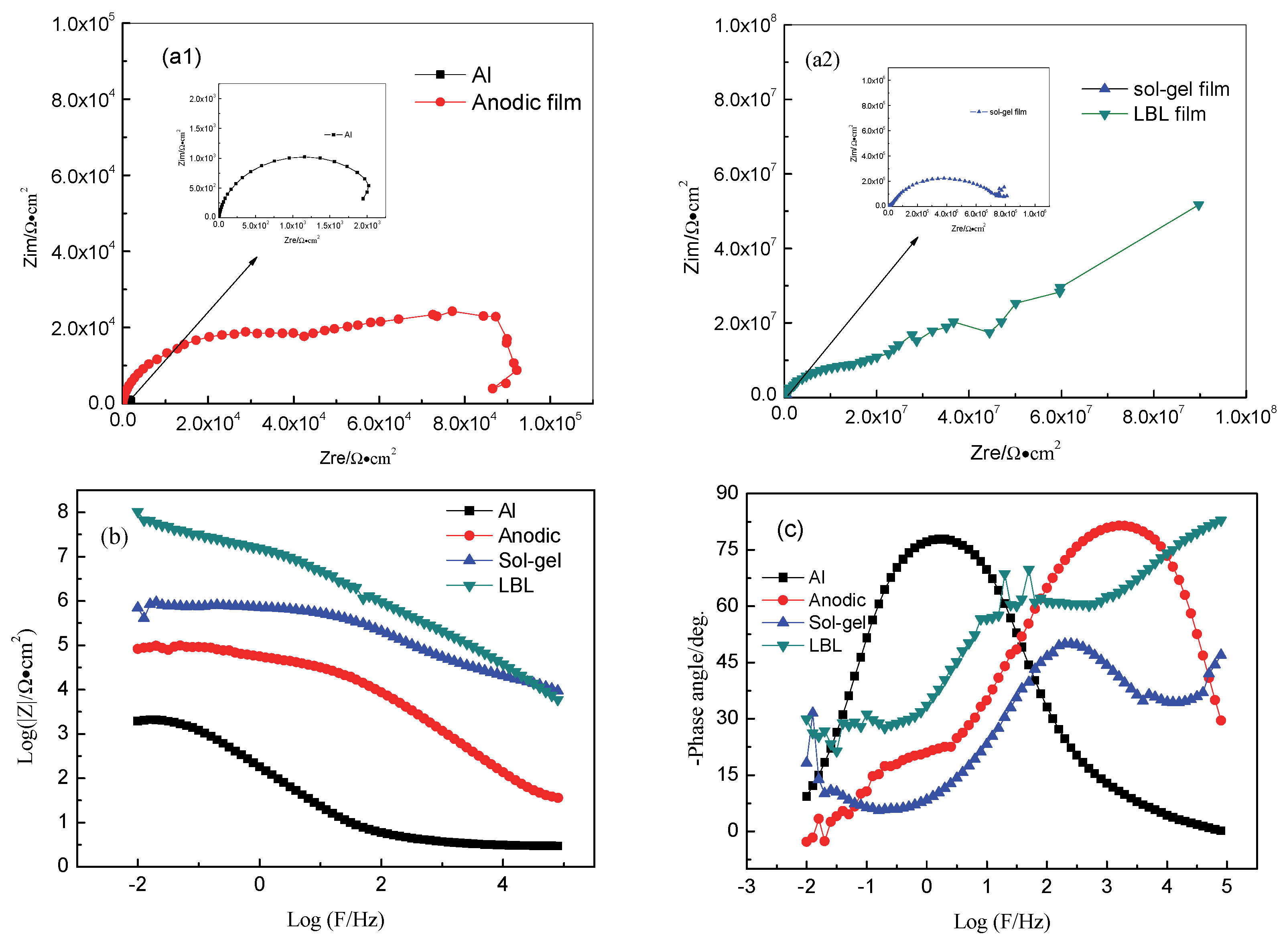
3.4. Anticorrosion Properties
3.5. The Polarization Curves Test
3.6. Salt Spray Tests
4. Conclusions
Author Contributions
Funding
Conflicts of Interest
References
- Sherif, E.S.M.; Ammar, H.R.; Khalil, K.A. Effects of copper and titanium on the corrosion behavior of newly fabricated nanocrystalline aluminum in natural seawater. Appl. Surf. Sci. 2014, 301, 142–148. [Google Scholar] [CrossRef]
- Huang, Y.; Shih, T.S.; Chou, J. Electrochemical behavior of anodized AA7075-T73 alloys as affected by the matrix structure. Appl. Surf. Sci. 2013, 283, 249–257. [Google Scholar] [CrossRef]
- Savaskan, T.; Murphy, S. Comparative wear behavior of Zn-Al based alloys in an automotive engine application. Wear 1984, 98, 151–161. [Google Scholar]
- Jian, H.; Yin, Z.; Jiang, F.; Li, X.; Nonfer, T. EBSD analysis of fatigue crack growth of 2124 aluminum alloy for aviation. Rare Met. Mater. Eng. 2014, 43, 1332–1336. [Google Scholar]
- Kotov, A.D.; Mikhaylovskaya, A.V.; Kishchik, M.S.; Tsarkov, A.A.; Aksenov, S.A.; Portnoy, V.K. Near net shape casting process for producing high strength 6xxx aluminum alloy automobile suspension parts. J. Alloys Compd. 2016, 688, 336–344. [Google Scholar] [CrossRef]
- Rac, A.; Babic, M.; Ninkovic, R.; Balk, J. Theory and practice of Zn-Al sliding bearings. J. Balk Tribol. Assoc. 2001, 7, 234–240. [Google Scholar]
- Babic, M.; Ninkovic, R. Zn-Al alloys as tribomaterials. Tribol. Ind. 2004, 26, 3–7. [Google Scholar]
- Babic, M.; Ninkvoic, R.; Rac, A. Sliding wear behavior of Zn-Al alloys in conditions of boundary lubrication. In The Annals of University: “Dunarea De Jos” of Galati Fascicle VIII, Tribology; The Annals of University: Galaţi, Romania, 2005; pp. 60–64. [Google Scholar]
- Lu, Z.; Wang, P.; Zhang, D. Super-hydrophobic film fabricated on aluminium surface as a barrier to atmospheric corrosion in a marine environment. Corros. Sci. 2015, 91, 287–296. [Google Scholar] [CrossRef]
- Vera, R.; Delgado, D.; Rosales, B.M. Effect of atmospheric pollutants on the corrosion of high power electrical conductors: Part 1. Aluminum and AA6201 alloy. Corros. Sci. 2006, 48, 2882–2900. [Google Scholar] [CrossRef]
- Hou, B.R.; Li, X.G.; Ma, X.M.; Du, C.W.; Zhang, D.W.; Zheng, M.; Xu, W.; Lu, D.; Ma, F.B. The corrosion cost of China. NPJ Mater. Degrad. 2017, 1, 4. [Google Scholar] [CrossRef]
- Mayén, J.; Abúndez, A. Correlation between mechanical properties and corrosion behavior of an Al 6061 alloy coated by 5% CH3COOH pressurized steam and RRA heat treated. Surf. Coat. Technol. 2017, 309, 344–354. [Google Scholar] [CrossRef]
- Abidi, F.; Savaloni, H. Surface nanostructure modification of Al substrates by N+ ion implantation and their corrosion inhibition. Trans. Nonferrous Met. Soc. China 2017, 27, 701–710. [Google Scholar] [CrossRef]
- Ou, J.; Hu, W.; Xue, M.; Wang, F.; Li, W. Superhydrophobic surfaces on light alloy substrates fabricated by a versatile process and their corrosion protection. ACS Appl. Mater. Interfaces 2013, 5, 3101–3107. [Google Scholar] [CrossRef] [PubMed]
- Caubert, F.; Taberna, P.L.; Arurault, L. Innovating pulsed electrophoretic deposition of boehmite nanoparticles dispersed in an aqueous solution, into a model porousanodic film, prepared on aluminum alloy 1050. Surf. Coat. Technol. 2016, 302, 293–301. [Google Scholar] [CrossRef]
- Hashimoto, T.; Zhou, X.; Skeldon, P.; Thompson, G.E. Structure of the copper-enriched layer introduced by anodic oxidation of copper-containing aluminum alloy. Electrochim. Acta 2015, 17, 394–401. [Google Scholar]
- Zhang, X.; Chen, W. Review on corrosion-wear resistance performance of materials in molten aluminum and its alloys. Trans. Nonferrous Met. Soc. China 2015, 25, 1715–1731. [Google Scholar] [CrossRef]
- Thaia, T.T.; Druarta, M.E.; Paintc, Y.; Trinhb, A.T.; Olivier, M.G. Influence of the sol-gel mesoporosity on the corrosion protection given by an epoxy primer applied on aluminum alloy 2024-T3. Prog. Org. Coat. 2018, 121, 53–63. [Google Scholar] [CrossRef]
- Li, S.; Huang, P.; Ye, Z.; Wang, Y.; Wang, W.; Kong, D.; Zhang, J.; Deng, L.; Dong, A. Layer-by-layer zwitterionic modification of diverse substrates with durable anti-corrosion and anti-fouling properties. J. Mater. Chem. B 2019, 7, 6024–6034. [Google Scholar] [CrossRef]
- Yan, R.; He, W.; Zhai, T.; Ma, H. Anticorrosion organic-inorganic hybrid films constructed on iron substrates using self-assembled polyacrylic acid as a functional bottom layer. Electrochimi. Acta 2019, 295, 942–955. [Google Scholar] [CrossRef]
- Poorteman, M.; Renaud, A.; Escobar, J.; Dumas, L.; Bonnaud, L.; Dubois, P.; Olivier, M.G. Thermal curing of paraphenylenediamine benzoxazine for barrier coating applications on 1050 aluminum alloys. Prog. Org. Coat. 2016, 97, 99–109. [Google Scholar] [CrossRef]
- Zheludkevich, M.L.; Salvado, I.M.; Ferreira, M. Sol-gel coatings for corrosion protection of metals. J. Mater. Chem. 2005, 15, 5099–5111. [Google Scholar] [CrossRef]
- Wankhede, R.G.; Morey, S.; Khanna, A.S.; Birbilis, N. Development of water-repellent organic-inorganic hybrid solegel coatings on aluminum using short chain perfluoro polymer emulsion. Appl. Surf. Sci. 2013, 283, 1051–1059. [Google Scholar] [CrossRef]
- Habazaki, H.; Kimura, T.; Aoki, Y.; Tsuji, E.; Yano, T. Highly enhanced corrosion resistance of stainless steel by sol-gel layer-by-layer aluminosilicate thin coatings. J. Electrochem. Soc. 2014, 161, C57–C61. [Google Scholar] [CrossRef]
- Kim, J.S.; Kand, T.H.; Kim, I.K. Surface treatment to improve corrosion resistance of Al plate heat exchangers. Trans. Nonferrous Met. Soc. China 2009, 19, 28–31. [Google Scholar] [CrossRef]
- Chen, D.; Zheng, J. Advances in technology of preparing anti-corrosion ceramic coating on metal surface with sol-gel process. Mater. Rev. 2002, 16, 28. [Google Scholar]
- Zheng, S.X.; Li, J.H. Inorganic-organic sol gel hybrid coatings for corrosion protection of metals. J. Sol-Gel Sci. Technol. 2010, 54, 174–187. [Google Scholar] [CrossRef]
- Nagode, A.; Jerina, K.; Jerman, I.; Vella, D.; Bizjak, M.; Kosec, B.; Karpe, B.; Zorc, B. The effect of sol-gel boehmite coatings on the corrosion and decarburization of C45 steel. J. Sol-Gel Sci. Technol. 2018, 86, 568–579. [Google Scholar] [CrossRef]
- Salazar-Hernández, C.; Salazar-Hernández, M.; Mendoza-Miranda, J.M.; Miranda-Avilés, R.; Elorza-Rodríguez, E.; Carrera-Rodríguez, R.; Puy-Alquiza, M.J. Organic modified silica obtained from DBTL polycondensation catalyst for anticorrosive coating. J. Sol-Gel Sci. Technol. 2018, 87, 299–309. [Google Scholar]
- Song, X.; Meng, F.; Kong, M.; Liu, Z.; Huang, L.; Zheng, X.; Zeng, Y. Relationship between cracks and microstructures in APS YSZ coatings at elevated temperatures. Mater. Charact. 2017, 131, 277–284. [Google Scholar] [CrossRef]
- Zhao, X.; Jin, Z.; Zhang, B.; Zhai, X.; Liu, S.; Sun, X.; Zhu, Q.; Hou, B. Effect of graphene oxide on anticorrosion performance of polyelectrolyte multilayer for 2A12 aluminum alloy substrates. RSC Adv. 2017, 7, 33764–33774. [Google Scholar] [CrossRef]
- Zhao, Y.; Shi, L.; Ji, X.; Li, J.; Han, Z.; Li, S.; Zeng, R.; Zhang, F.; Wang, Z. Corrosion resistance and antibacterial properties of polysiloxane modified layer-by-layer assembled self-healing coating on magnesium alloy. J. Colloid Interface Sci. 2018, 526, 43–50. [Google Scholar] [CrossRef]
- Skorb, E.V.; Andreeva, D.V. Layer-by-Layer approaches for formation of smart self-healing materials. Polym. Chem. 2013, 4, 4834–4845. [Google Scholar] [CrossRef]
- Carneiro, J.; Caetano, A.; Kuznetsova, A.; Maia, F.; Salak, A.; Tedim, J.; Scharnagl, N.; Zheludkevich, M.; Ferreira, M. Polyelectrolyte-modified layered double hydroxide nanocontainers as vehicles for combined inhibitors. RSC Adv. 2015, 5, 39916–39929. [Google Scholar] [CrossRef]
- Liu, P.; Cai, K.; Yang, W. Improved anticorrosion of magnesium alloy via layer-by-layer self-assembly technique combined with micro-arc oxidation. Mater. Lett. 2012, 75, 118–121. [Google Scholar] [CrossRef]
- Decher, G. Fuzzy nanoassemblies: Toward layered polymeric multicomposites. Science 1997, 277, 1232–1237. [Google Scholar] [CrossRef]
- Yang, Y.H.; Haile, M.; Park, Y.T.; Malek, F.A.; Grunlan, J.C. Super Gas Barrier of All-Polymer Multilayer Thin Films. Macromolecules 2011, 44, 1450–1459. [Google Scholar] [CrossRef]
- Li, D.; Mao, W.M.; Jiang, H. Influence of surface dislocation and scratch of purity aluminum crystals on the initiation of pit etching. Electron. Compon. Mater. 2009, 33, 81–91. [Google Scholar]
- Zhang, B.; Zhao, X.; Li, Y.; Hou, B. Fabrication of durable anticorrosion superhydrophobic surfaces on aluminum substrates via a facile one-step electrode position approach. RSC Adv. 2016, 6, 35455–35465. [Google Scholar] [CrossRef]
- Zhao, X.; Wang, J.; Li, W.; Hou, B. Research on coating deterioration process under fully immersing condition by using multi-parameters. Mater. Corros. 2011, 5, 431–435. [Google Scholar] [CrossRef]
- Wang, P.; Zhang, D.; Qiu, R.; Wu, J. Super-hydrophobic metal-complex film fabricated electrochemically on copper as a barrier to corrosive medium. Corros. Sci. 2014, 83, 317–326. [Google Scholar] [CrossRef]
- Zhao, X.; Wang, J.; Wang, Y.; Kong, T.; Zhong, L.; Zhang, W. Analysis of deterioration process of organic protective coating using EIS assisted by SOM network. Electrochem. Commun. 2007, 9, 1394–1399. [Google Scholar] [CrossRef]
- Zhang, B.B.; Guan, F.; Zhao, X.; Zhang, Y.; Li, Y.; Duan, J.; Hou, B. Micro-nano textured superhydrophobic 5083 aluminum alloy as a barrier against marine corrosion and sulfate-reducing bacteria adhesion. J. TaiWan Inst. Chem. E 2019, 97, 433–440. [Google Scholar] [CrossRef]
- Xue, B.; Yu, M.; Liu, J.; Liu, J.; Li, S.; Xiong, L. Corrosion protection of AA2024-T3 by sol-gel film modified with graphene oxide. J. Alloy Compd. 2017, 725, 84–95. [Google Scholar] [CrossRef]
- Zhao, X.; Liu, S.; Wang, X.; Hou, B.R. Surface modification of ZrO2 nanoparticles with styrene coupling agent and its effect on the corrosion behavior of epoxy coating. Chin. J. Oceanol. Limnol. 2014, 32, 1163–1171. [Google Scholar] [CrossRef]


| Sample | Qdl | n | Rct | Qc | n | Rc | QLBL | n | RLBL | η |
|---|---|---|---|---|---|---|---|---|---|---|
| Y0dl Ω−1cm−2sn | Ω·cm2 | Y0dl Ω−1cm−2sn | Ω·cm2 | Y0LBL Ω−1cm−2sn | Ω·cm2 | % | ||||
| Al alloy | 0.00106 | 0.88 | 2446 | \ | \ | \ | \ | \ | \ | |
| Oxide film | 2.95 × 10⁻⁷ | 0.93 | 3.25 × 10⁴ | 5.94 × 10⁻⁶ | 0.83 | 6.29 × 10⁴ | \ | \ | \ | 92.5 |
| Sol–gel film | 4.42 × 10⁻⁹ | 0.75 | 3.58 × 10⁴ | 4.74 × 10⁻⁸ | 0.69 | 7.54 × 10⁵ | \ | \ | \ | 93.2 |
| LBL film | 0.76 × 10⁻¹¹ | 0.93 | 1.30 × 10⁵ | 0.79 × 10⁻¹⁰ | 0.87 | 9.03 × 10⁶ | 0.45 × 10⁻⁹ | 0.52 | 1.32 × 10⁸ | 98.1 |
© 2019 by the authors. Licensee MDPI, Basel, Switzerland. This article is an open access article distributed under the terms and conditions of the Creative Commons Attribution (CC BY) license (http://creativecommons.org/licenses/by/4.0/).
Share and Cite
Zhao, X.; Yuan, S.; Jin, Z.; Zhang, B.; Liu, N.; Chen, S.; Liu, S.; Sun, X.; Duan, J. Perfect Combination of LBL with Sol–Gel Film to Enhance the Anticorrosion Performance on Al Alloy under Simulated and Accelerated Corrosive Environment. Materials 2020, 13, 111. https://doi.org/10.3390/ma13010111
Zhao X, Yuan S, Jin Z, Zhang B, Liu N, Chen S, Liu S, Sun X, Duan J. Perfect Combination of LBL with Sol–Gel Film to Enhance the Anticorrosion Performance on Al Alloy under Simulated and Accelerated Corrosive Environment. Materials. 2020; 13(1):111. https://doi.org/10.3390/ma13010111
Chicago/Turabian StyleZhao, Xia, Shuai Yuan, Zuquan Jin, Binbin Zhang, Nazhen Liu, Shibo Chen, Shuan Liu, Xiaolin Sun, and Jizhou Duan. 2020. "Perfect Combination of LBL with Sol–Gel Film to Enhance the Anticorrosion Performance on Al Alloy under Simulated and Accelerated Corrosive Environment" Materials 13, no. 1: 111. https://doi.org/10.3390/ma13010111
APA StyleZhao, X., Yuan, S., Jin, Z., Zhang, B., Liu, N., Chen, S., Liu, S., Sun, X., & Duan, J. (2020). Perfect Combination of LBL with Sol–Gel Film to Enhance the Anticorrosion Performance on Al Alloy under Simulated and Accelerated Corrosive Environment. Materials, 13(1), 111. https://doi.org/10.3390/ma13010111