The Influence of Process Parameters and Build Orientation on the Creep Behaviour of a Laser Powder Bed Fused Ni-based Superalloy for Aerospace Applications

 ,
, 
Abstract
1. Introduction
2. Materials and Methods
2.1. Material
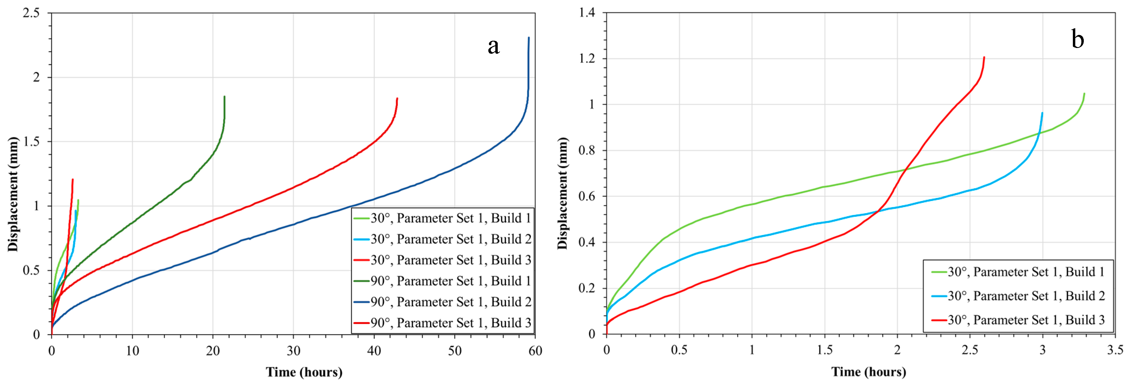
2.2. Small Punch Creep Testing
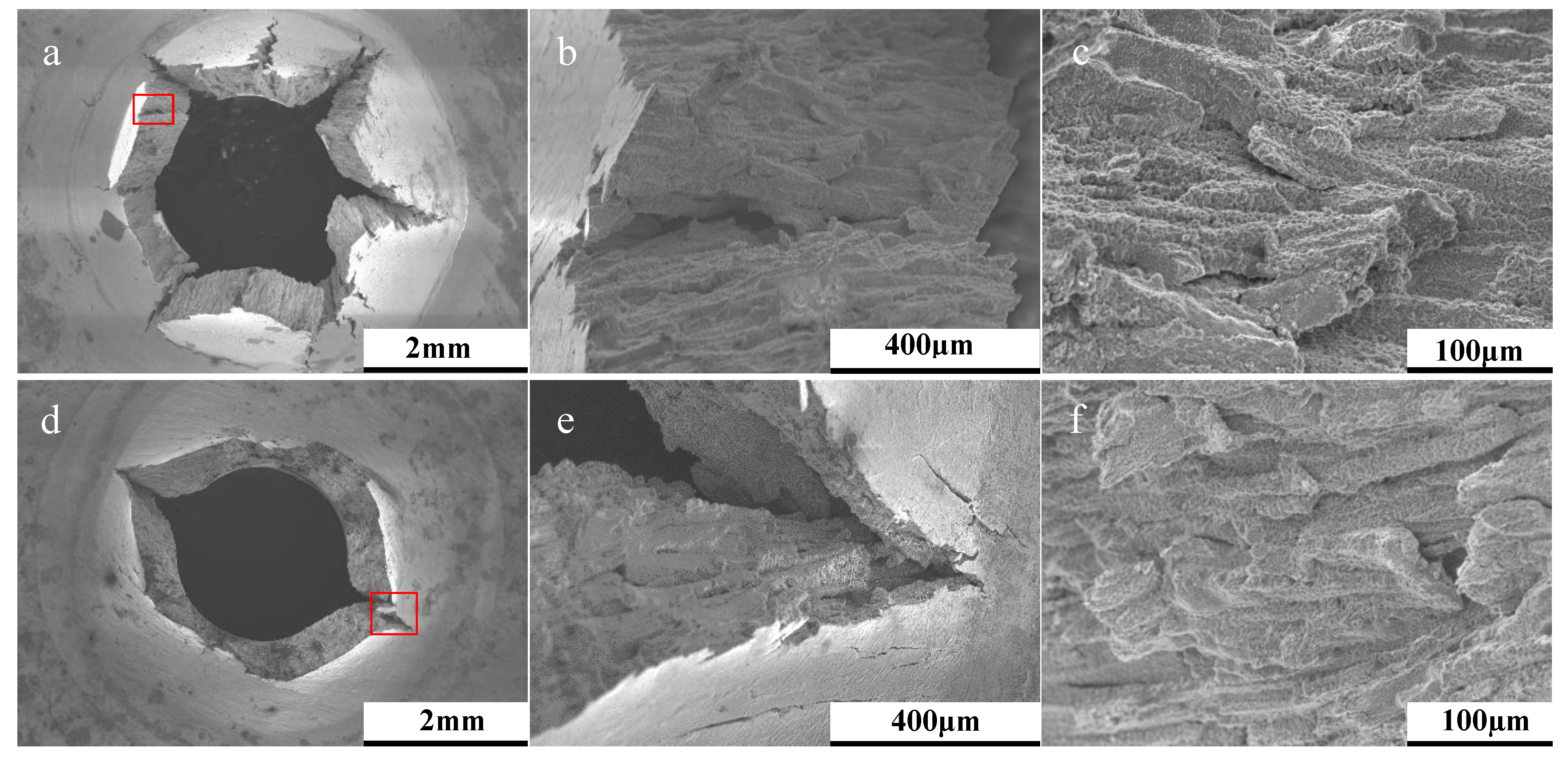
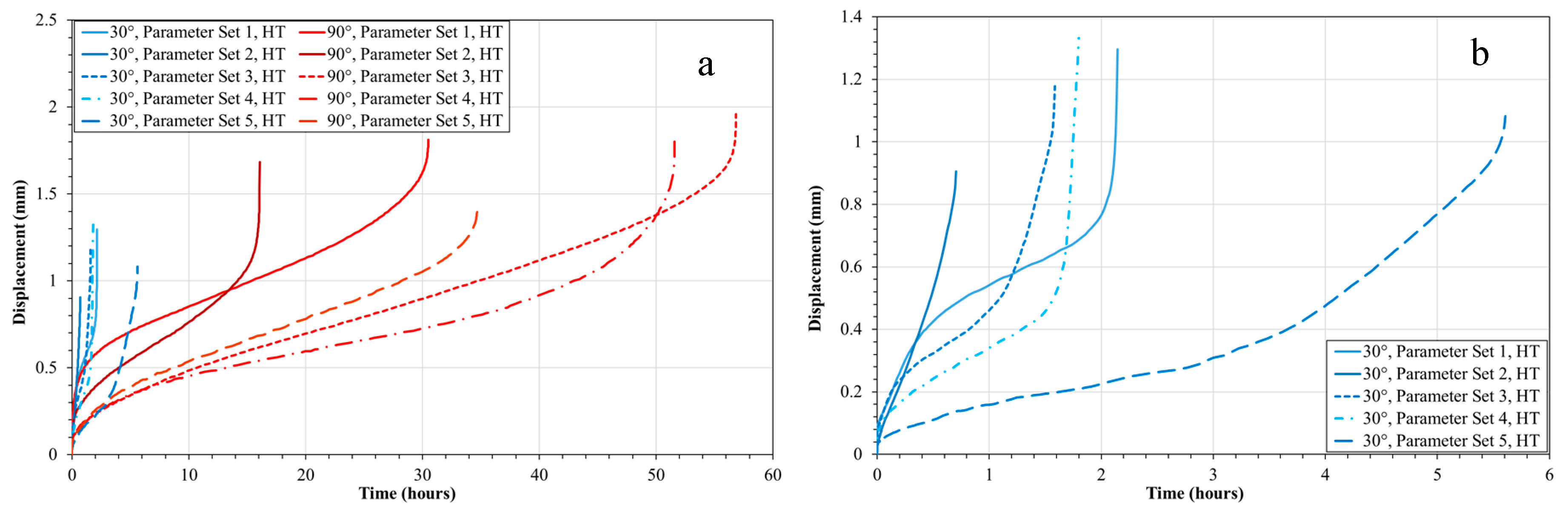
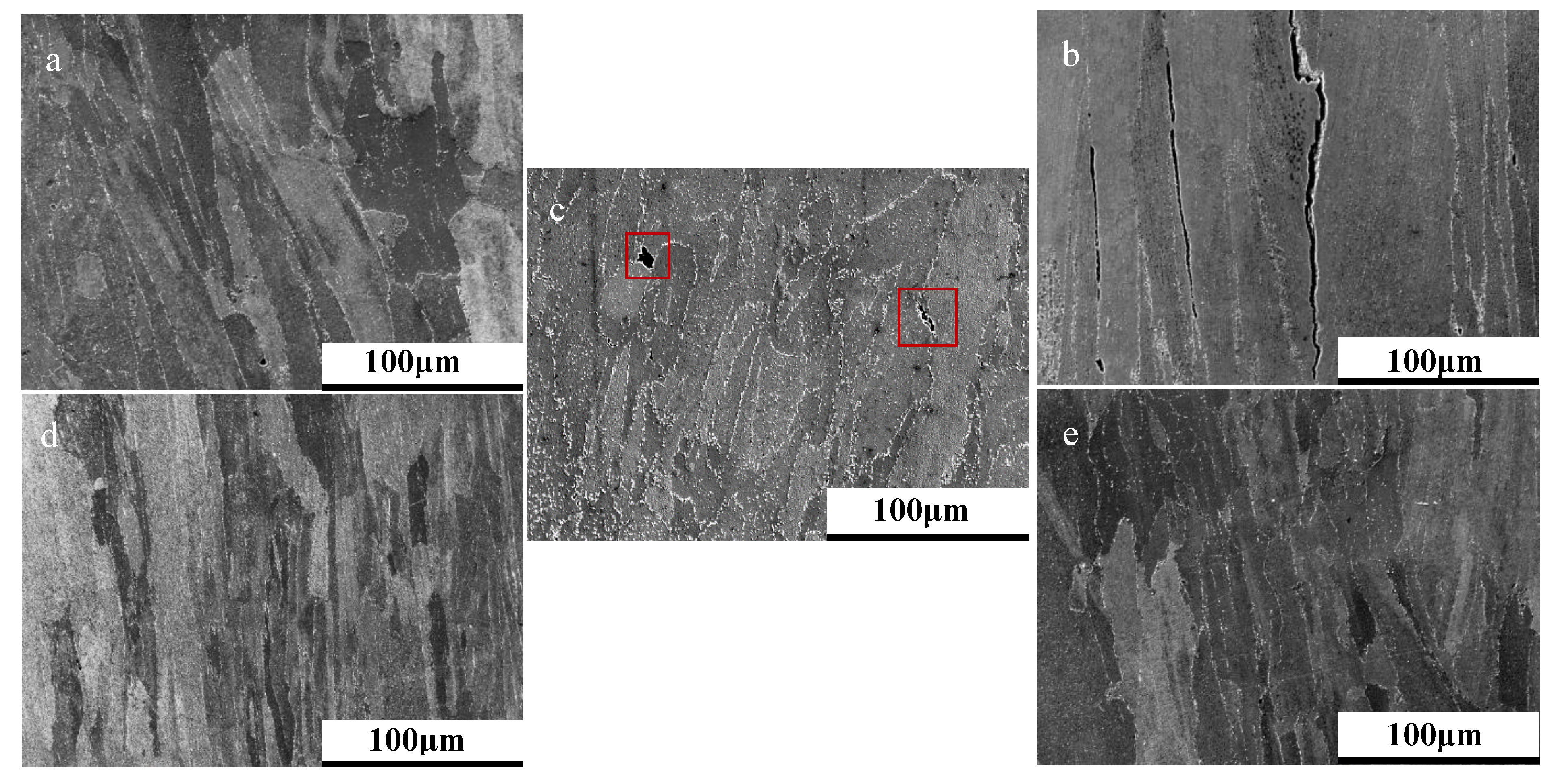
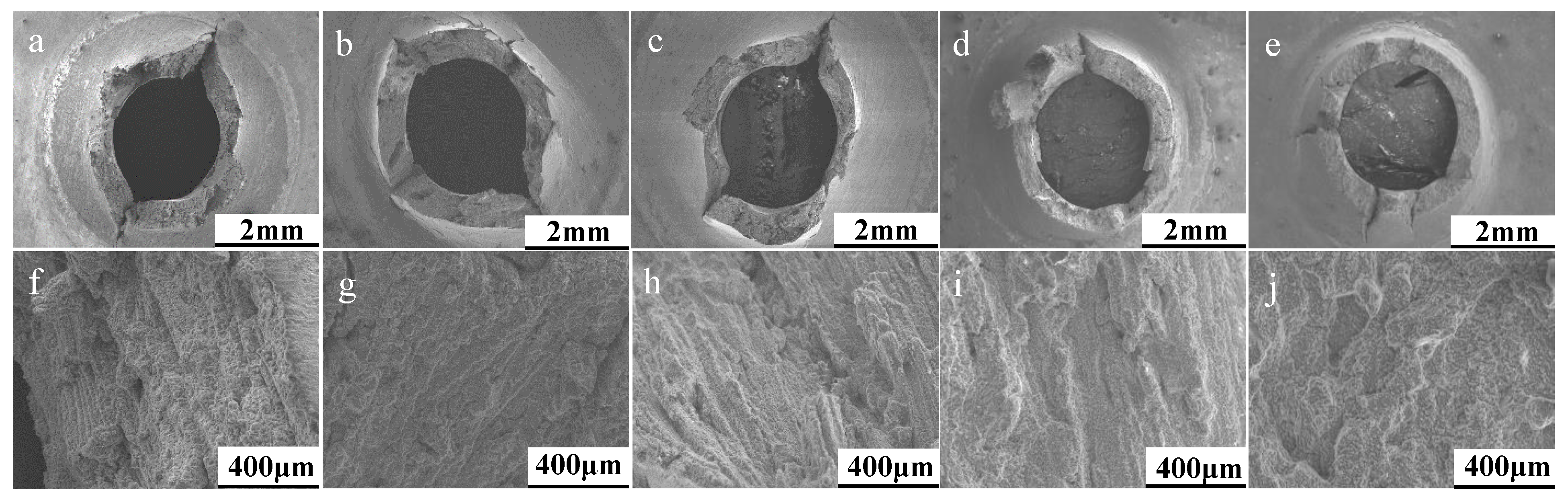
3. Results and Discussion
4. Conclusions
Author Contributions
Funding
Conflicts of Interest
References
- Pollock, T.M.; Tin, S. Nickel-Based Superalloys for Advanced Turbine Engines: Chemistry, Microstructure, and Properties. J. Propuls. Power 2006, 22, 361–374. [Google Scholar] [CrossRef]
- Royce, R. The Jet Engine; Rolls-Royce plc: Derby, UK, 2005. [Google Scholar]
- Reed, R.C. The Superalloys Fundamentals and Applications; Cambridge University Press: Cambridge, UK, 2006. [Google Scholar]
- Frazier, W.E. Metal Additive Manufacturing: A Review. J. Mater. Eng. Perform. 2014, 23, 1917–1928. [Google Scholar] [CrossRef]
- DebRoy, T.; Wei, H.L.; Zuback, J.S.; Mukherjee, T.; Elmer, J.W.; Milewski, J.O.; Breese, A.M.; Wilson-Heid, A.; De, A.; Zhang, W. Additive manufacturing of metallic components—Process, structure and properties. Prog. Mater. Sci. 2018, 92, 112–224. [Google Scholar] [CrossRef]
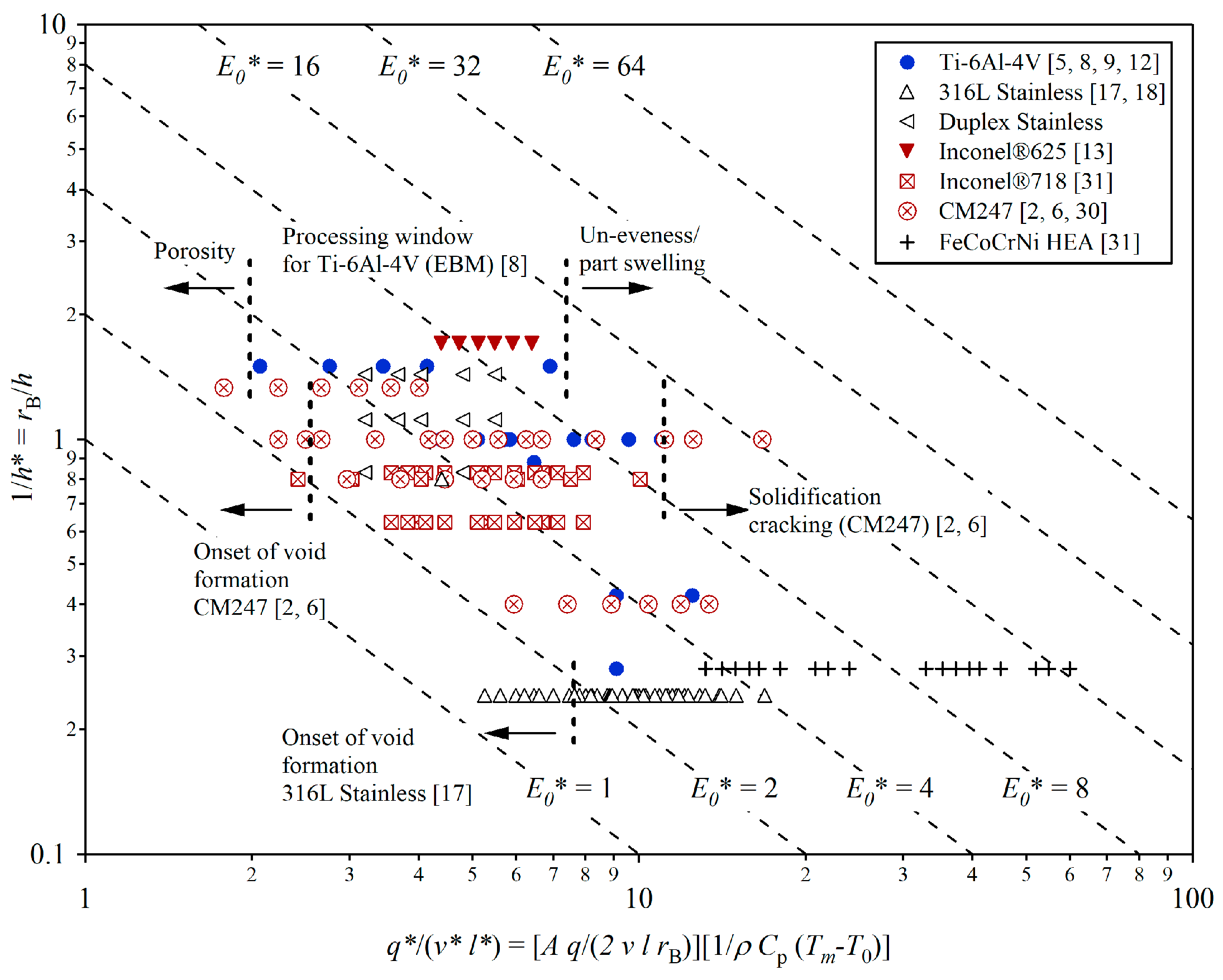
- Thomas, M.; Baxter, G.J.; Todd, I. Normalised model-based processing diagrams for additive layer manufacture of engineering alloys. Acta Mater. 2016, 108, 26–35. [Google Scholar] [CrossRef]
- Carter, L.N.; Essa, K.; Attallah, M. Optimisation of Selective Laser Melting for a High Temperature Ni-Superalloy. Rapid Prototyp. J. 2015, 21, 1–8. [Google Scholar] [CrossRef]
- Lewandowski, J.J.; Seifi, M. Metal Additive Manufacturing: A Review of Mechanical Properties. Annu. Rev. Mater. Res. 2016, 46, 151–186. [Google Scholar] [CrossRef]
- Slotwinski, J.A.; Cooke, A.L.; Moylan, S.P. Mechanical Properties Testing for Metal Parts Made via Additive Manufacturing: A Review of the State of the Art of Mechanical Property Testing; National Institute of Standards and Technology: Gaithersburg, MD, USA, 2012. [Google Scholar]
- Hilal, H.; Lancaster, R.J.; Jeffs, S.P.; Ednie, L.; Boswell, J.; Stapleton, D.; Baxter, G.J. High temperature mechanical deformation of an additively manufactured nickel-based superalloy using small scale testing methods. In Proceedings of the 5th International Small Sample Testing Techniques Conference, Swansea University, Swansea, Wales, UK, 10–12 July 2018. [Google Scholar]
- Lancaster, R.J.; Jeffs, S.P. Small Punch Creep. In Creep; Tanski, T., Sroka, M., Zielinski, A., Eds.; InTech Open: London, UK, 2018. [Google Scholar]
- Bruchhausen, M.; Holmström, S.; Simonovski, I.; Austin, T.; Lapetite, J.M.; Ripplinger, S.; de Haan, F. Recent developments in small punch testing: Tensile properties and DBTT. Theor. Appl. Fract. Mech. 2016, 86, 2–10. [Google Scholar] [CrossRef]
- Soyarslan, C.; Gülçimen, B.; Bargmann, S.; Hähner, P. Modeling of fracture in small punch tests for small- and large-scale yielding conditions at various temperatures. Int. J. Mech. Sci. 2016, 106, 266–285. [Google Scholar] [CrossRef]
- Lancaster, R.J.; Jeffs, S.P.; Illsley, H.W.; Argyrakis, C.; Hurst, R.C.; Baxter, G.J. Development of a novel methodology to study fatigue properties using the small punch test. Mater. Sci. Eng. A 2019, 748, 21–29. [Google Scholar] [CrossRef]
- Davies, S.J.; Jeffs, S.P.; Coleman, M.P.; Lancaster, R.J. Effects of heat treatments on microstructure and creep properties of a laser powder bed fused nickel superalloy. Mater. Des. 2018, 159, 39–46. [Google Scholar] [CrossRef]
- Lancaster, R.J.; Davies, G.; Illsley, H.; Jeffs, S.P.; Baxter, G.J. Structural Integrity of an Electron Beam Melted Titanium Alloy. Materials 2016, 9, 470. [Google Scholar] [CrossRef] [PubMed]
- Maldini, M.; Marchionni, M.; Nazmy, M.; Staubli, M.; Osinkolu, G. Creep and fatigue properties of a directionally solidified nickel base superalloy at elevated temperature. In Proceedings of the Eighth Internal Symposium on Superalloys, Champion, PA, USA, 22–26 September 1996; TMS: Seven Springs, Champion, PA, USA, 1996; pp. 327–334. [Google Scholar]
- Satyanarayana, D.V.V.; Omprakash, C.M.; Jagadeesan, B.; Das, N. Effect of section thickness on creep and stress rupture behaviour of DS CM247 nickel base superalloy. Mater. High Temp. 2008, 25, 17–26. [Google Scholar] [CrossRef]
- Carter, L.N.; Attallah, M.A.; Reed, R.C. Laser powder bed fabrication of nickel-based superalloys: Influece of parameters, characterisation, quantification and mitigation of cracking. In Superalloys 2012; Huron, E.S., Reed, R.C., Hardy, M.C., Mills, M.J., Montero, R.E., Portella, P.D., Carter, L.N., Telesman, J., Eds.; John Wiley & Sons, Inc.: Hoboken, NJ, USA, 2012; pp. 577–608. [Google Scholar]
- European Code of Practice: Small Punch Test Method for Metallic Materials. In CEN Workshop Agreement CWA 15267; Committee of European Norms (CEN): Brussels, Belgium, 2007.
- Jeffs, S.P.; Lancaster, R.J. Elevated temperature creep deformation of a single crystal superalloy through the small punch creep method. Mater. Sci. Eng. A 2015, 626, 330–337. [Google Scholar] [CrossRef]
- Boswell, J. Development of Aero Engine Component Manufacturing Using Laser Additive Manufacturing, MERLIN Final Report. 2014. Available online: https://cordis.europa.eu/project/rcn/97209/reporting/en (accessed on 25 April 2019).
- Dobeš, F.; Milička, K. On the Monkman–Grant relation for small punch test data. Mater. Sci. Eng. A 2002, 336, 245–248. [Google Scholar] [CrossRef]


| Notation | Process Variables & Material Properties | Units | Notation | Process Variables & Material Properties | Units |
|---|---|---|---|---|---|
| A | Surface Absorptivity | - | q* | Normalised Power | - |
| Cp | Specific Heat Capacity | J kg−1 K−1 | rB | Beam Radius | M |
| E0* | Normalised Energy Density | - | Tm | Melting Temperature | K |
| h | Hatch Spacing | m | T0 | Initial Powder Bed Temperature | K |
| h* | Normalised Hatch Spacing | - | v | Beam Velocity | ms−1 |
| ρ | Density | kg m−3 | V* | Normalised Beam Velocity | - |
| q | Power | W |
| C | Cr | Ni | Co | Mo | W | Ta |
| 0.07 | 8 | Bal. | 9 | 0.5 | 10 | 3.2 |
| Ti | Al | B | Zr | Hf | Si | S |
| 0.7 | 5.6 | 0.015 | 0.01 | 1.4 | 0.03 | 15 ppm |
| DOE Parameter Set | q*/(v*·l*) | 1/h* | E* |
|---|---|---|---|
| 1 | Medium | Medium | Medium |
| 2 | High | High | High |
| 3 | Low | Low | Low |
| 4 | High | Low | Medium |
| 5 | Low | High | Medium |
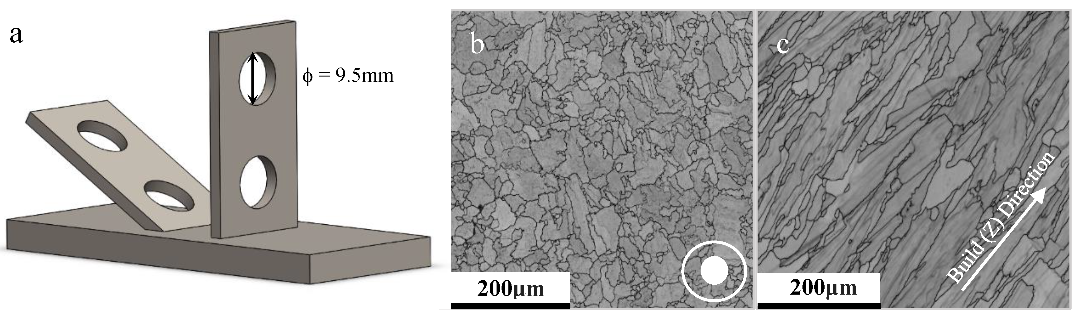
| Sample ID | Average Grain Area (μm2) | Average Grain Aspect Ratio | Average Grain Diameter (µm) | Number of Grains Analysed |
|---|---|---|---|---|
| 30°, Parameter Set 1, HT | 175 | 1.90 | 9.9 | 1334 |
| 90°, Parameter Set 1, HT | 863 | 3.79 | 20.4 | 378 |
| 90°, Parameter Set 2, HT | 811 | 3.67 | 13.0 | 477 |
| 90°, Parameter Set 2, AB | 1278 | 3.69 | 21.5 | 284 |
| 90°, Parameter Set 3, HT | 1024 | 2.98 | 19.7 | 311 |
| 90°, Parameter Set 4, HT | 964 | 3.43 | 20.1 | 337 |
| 90°, Parameter Set 5, HT | 1129 | 2.74 | 21.4 | 299 |
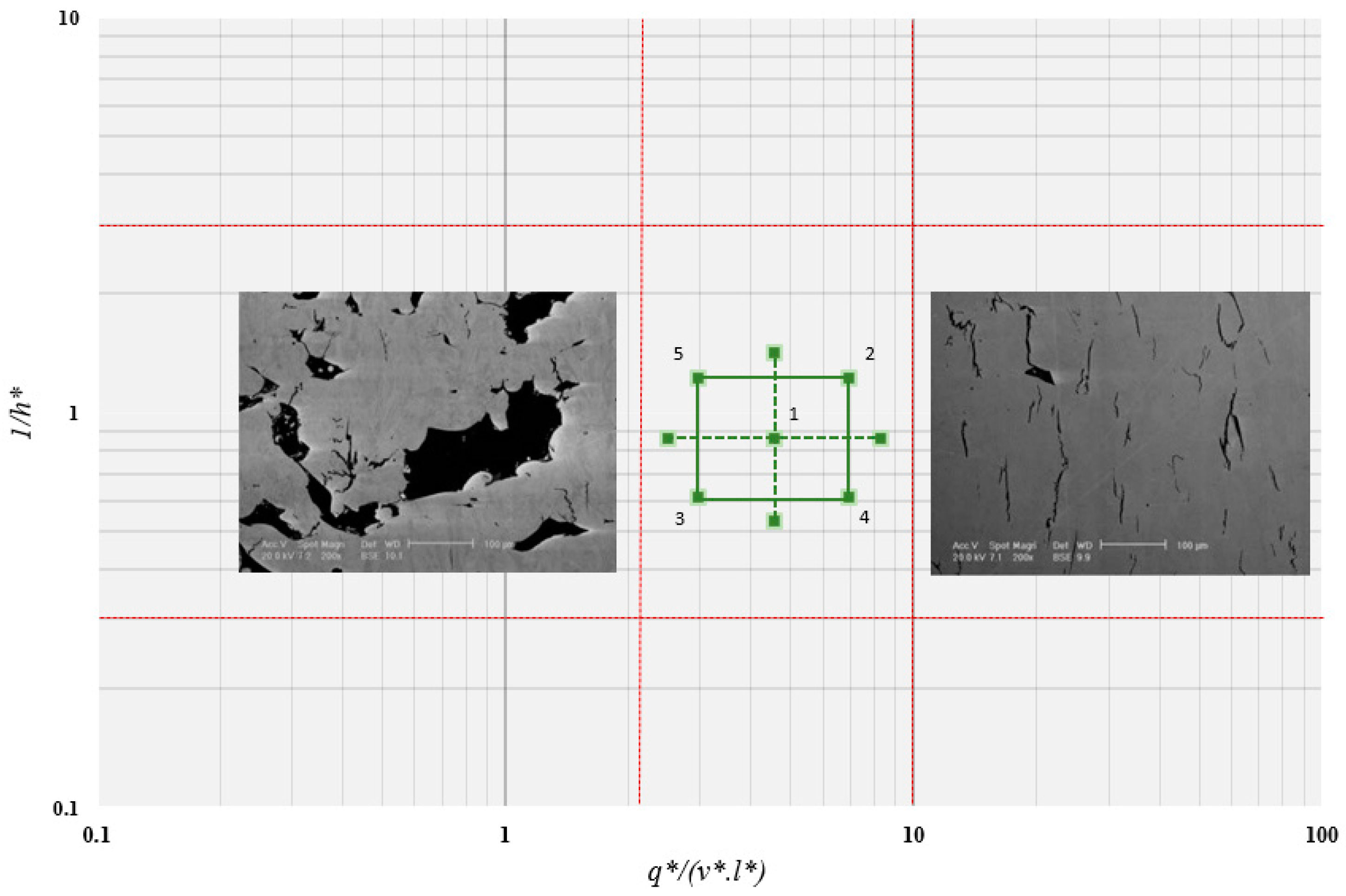
| Sample | Microcracking (% Area) | Porosity (% Area) |
|---|---|---|
| 30°, Parameter Set 2, AB | 1.70 | 0.51 |
| 30°, Parameter Set 2, HT | 0.31 | 0.50 |
| 90°, Parameter Set 2, AB | 1.00 | 0.35 |
| 90°, Parameter Set 2, HT | 1.67 | 0.33 |
© 2019 by the authors. Licensee MDPI, Basel, Switzerland. This article is an open access article distributed under the terms and conditions of the Creative Commons Attribution (CC BY) license (http://creativecommons.org/licenses/by/4.0/).
Share and Cite
Hilal, H.; Lancaster, R.; Jeffs, S.; Boswell, J.; Stapleton, D.; Baxter, G. The Influence of Process Parameters and Build Orientation on the Creep Behaviour of a Laser Powder Bed Fused Ni-based Superalloy for Aerospace Applications. Materials 2019, 12, 1390. https://doi.org/10.3390/ma12091390
Hilal H, Lancaster R, Jeffs S, Boswell J, Stapleton D, Baxter G. The Influence of Process Parameters and Build Orientation on the Creep Behaviour of a Laser Powder Bed Fused Ni-based Superalloy for Aerospace Applications. Materials. 2019; 12(9):1390. https://doi.org/10.3390/ma12091390
Chicago/Turabian StyleHilal, Hani, Robert Lancaster, Spencer Jeffs, John Boswell, David Stapleton, and Gavin Baxter. 2019. "The Influence of Process Parameters and Build Orientation on the Creep Behaviour of a Laser Powder Bed Fused Ni-based Superalloy for Aerospace Applications" Materials 12, no. 9: 1390. https://doi.org/10.3390/ma12091390
APA StyleHilal, H., Lancaster, R., Jeffs, S., Boswell, J., Stapleton, D., & Baxter, G. (2019). The Influence of Process Parameters and Build Orientation on the Creep Behaviour of a Laser Powder Bed Fused Ni-based Superalloy for Aerospace Applications. Materials, 12(9), 1390. https://doi.org/10.3390/ma12091390