AC-Filtering Supercapacitors Based on Edge Oriented Vertical Graphene and Cross-Linked Carbon Nanofiber


Abstract

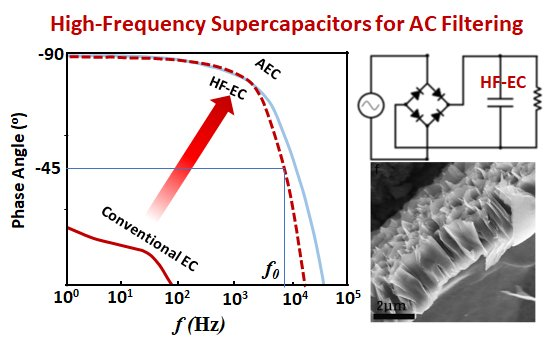
1. Introduction
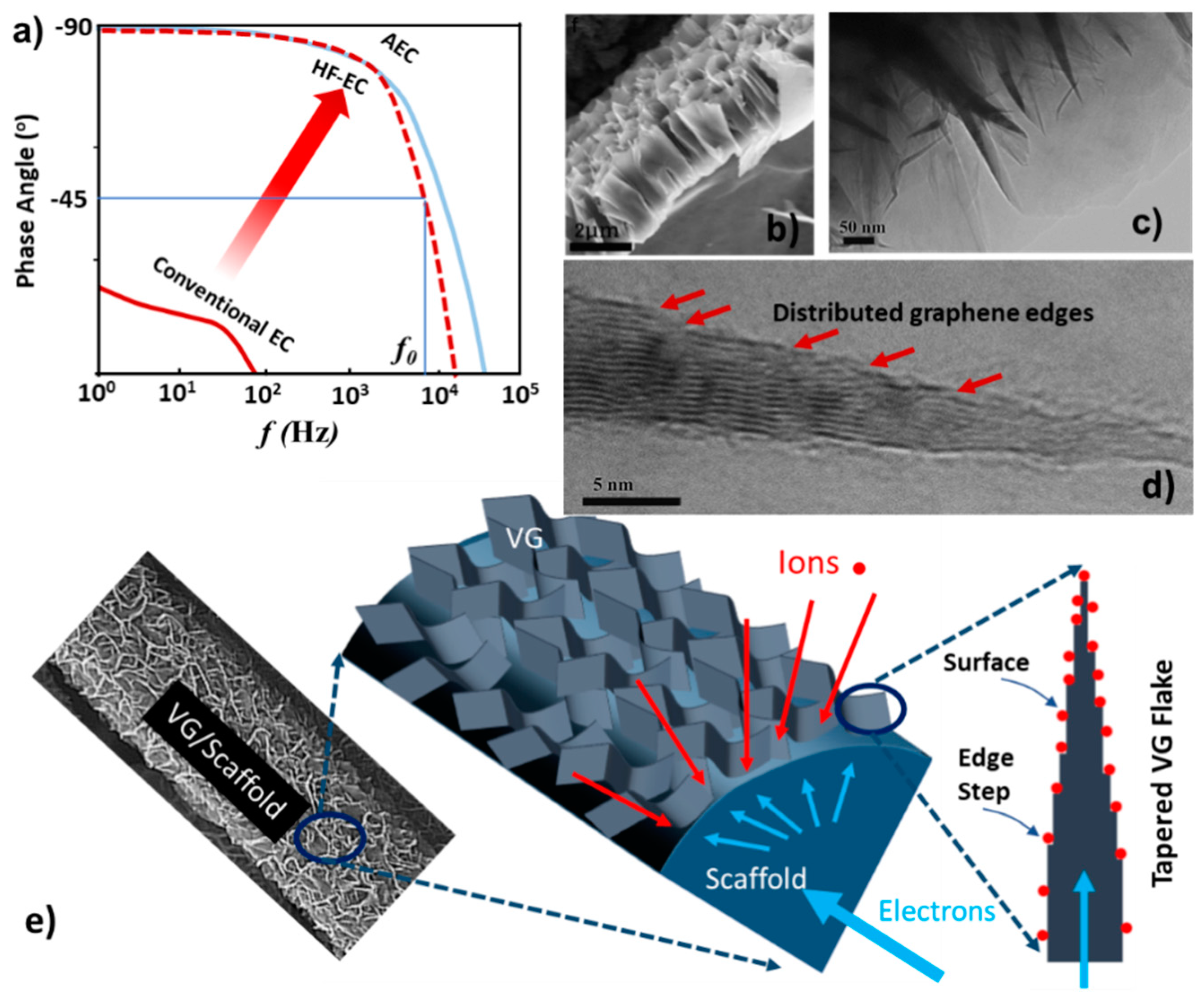
2. VG Structure Growth
3. VG on Ni Foam
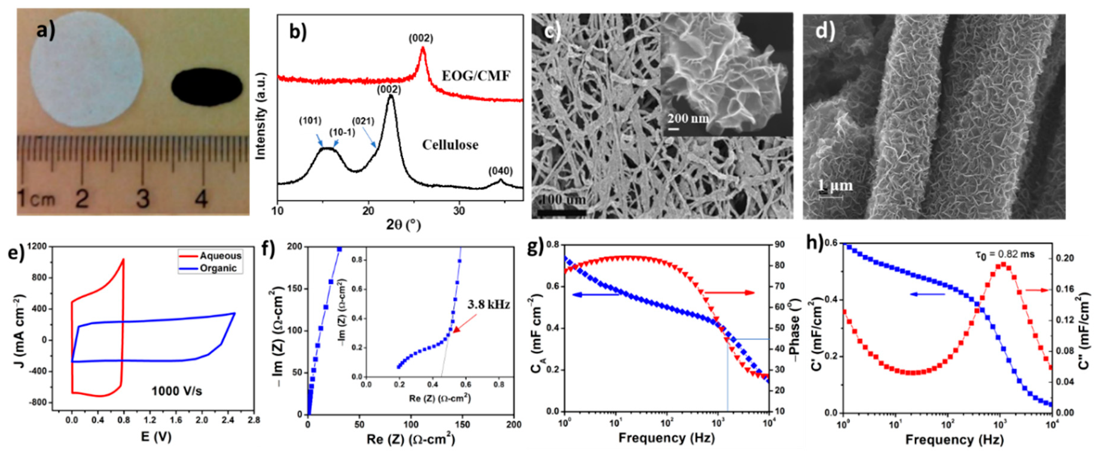
4. VG on Carbon Fiber Sheets
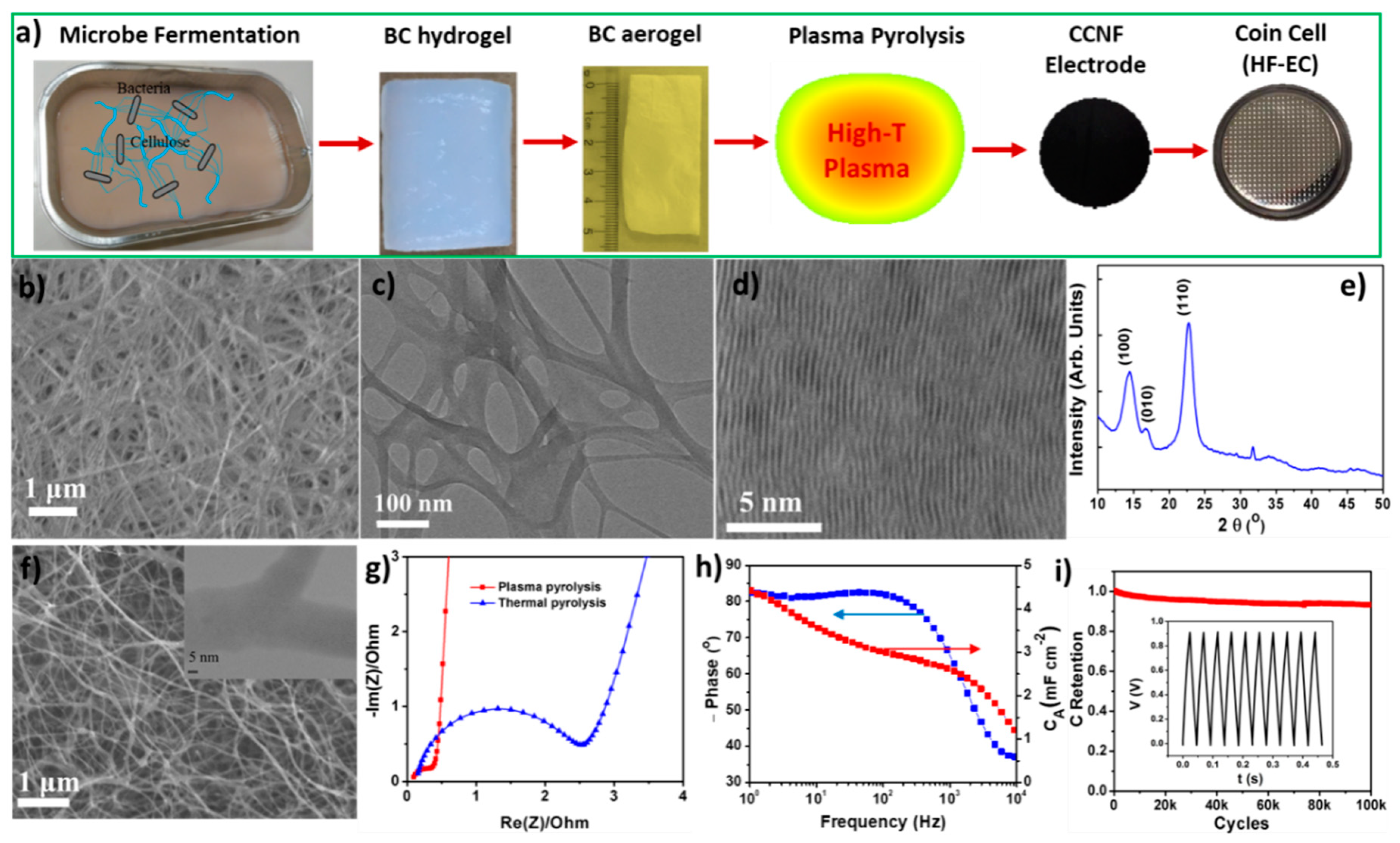
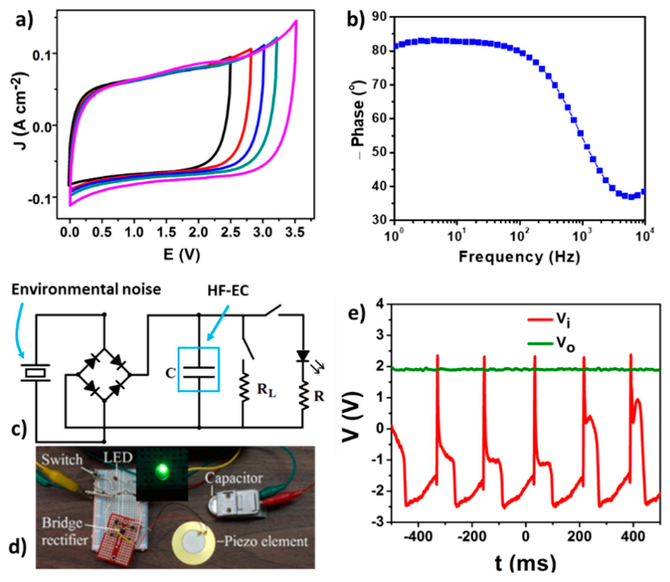
5. Cross-Linked Carbon Nanofiber Derived from Bacterial Cellulose Aerogel
6. Conclusions
Funding
Conflicts of Interest
References
- Fan, Z.; Islam, N.; Bayne, S.B. Towards kilohertz electrochemical capacitors for filtering and pulse energy harvesting. Nano Energy 2017, 39, 306–320. [Google Scholar] [CrossRef]
- Miller, J.R.; Outlaw, R.A.; Holloway, B.C. Graphene double-layer capacitor with ac line-filtering performance. Science 2010, 329, 1637–1639. [Google Scholar] [CrossRef] [PubMed]
- Sheng, K.; Sun, Y.; Li, C.; Yuan, W.; Shi, G. Ultrahigh-rate supercapacitors based on eletrochemically reduced graphene oxide for ac line-filtering. Sci. Rep. 2012, 2, 247. [Google Scholar] [CrossRef] [PubMed]
- Cai, M.; Outlaw, R.A.; Butler, S.M.; Miller, J.R. A high density of vertically-oriented graphenes for use in electric double layer capacitors. Carbon 2012, 50, 5481–5488. [Google Scholar] [CrossRef]
- Ren, G.; Pan, X.; Bayne, S.; Fan, Z. Kilohertz ultrafast electrochemical supercapacitors based on perpendicularly-oriented graphene grown inside of nickel foam. Carbon 2014, 71, 94–101. [Google Scholar] [CrossRef]
- Ren, G.; Li, S.; Fan, Z.-X.; Hoque, M.N.F.; Fan, Z. Ultrahigh-rate supercapacitors with large capacitance based on edge oriented graphene coated carbonized cellulous paper as flexible freestanding electrodes. J. Power Sources 2016, 325, 152–160. [Google Scholar] [CrossRef]
- Miller, J.R.; Outlaw, R.A. Vertically-oriented graphene electric double layer capacitor designs. J. Electrochem. Soc. 2015, 162, A5077–A5082. [Google Scholar] [CrossRef]
- Zhang, M.; Zhou, Q.; Chen, J.; Yu, X.; Huang, L.; Li, Y.; Li, C.; Shi, G. An ultrahigh-rate electrochemical capacitor based on solution-processed highly conductive PEDOT: PSS films for AC line-filtering. Energy Environ. Sci. 2016, 9, 2005–2010. [Google Scholar] [CrossRef]
- Islam, N.; Hoque, M.N.F.; Li, W.; Wang, S.; Warzywoda, J.; Fan, Z. Vertically edge-oriented graphene on plasma pyrolyzed cellulose fibers and demonstration of kilohertz high-frequency filtering electrical double layer capacitors. Carbon 2019, 141, 523–530. [Google Scholar] [CrossRef]
- Kossyrev, P. Carbon black supercapacitors employing thin electrodes. J. Power Sources 2012, 201, 347–352. [Google Scholar] [CrossRef]
- Strauss, V.; Anderson, M.; Turner, C.L.; Kaner, R.B. Fast response electrochemical capacitor electrodes created by laser-reduction of carbon nanodots. Mater. Today Energy 2019, 11, 114–119. [Google Scholar] [CrossRef]
- Zhao, M.; Nie, J.; Li, H.; Xia, M.; Liu, M.; Zhang, Z.; Liang, X.; Qi, R.; Wang, Z.L.; Lu, X. High-frequency supercapacitors based on carbonized melamine foam as energy storage devices for triboelectric nanogenerators. Nano Energy 2019, 55, 447–453. [Google Scholar] [CrossRef]
- Islam, N.; Li, S.; Ren, G.; Zu, Y.; Warzywoda, J.; Wang, S.; Fan, Z. High-frequency electrochemical capacitors based on plasma pyrolyzed bacterial cellulose aerogel for current ripple filtering and pulse energy storage. Nano Energy 2017, 40, 107–114. [Google Scholar] [CrossRef]
- Yoo, Y.; Kim, S.; Kim, B.; Kim, W. 2.5 V compact supercapacitors based on ultrathin carbon nanotube films for AC line filtering. J. Mater. Chem. A 2015, 3, 11801–11806. [Google Scholar] [CrossRef]
- Rangom, Y.; Tang, X.S.; Nazar, L.F. Carbon Nanotube-Based Supercapacitors with Excellent ac Line Filtering and Rate Capability via Improved Interfacial Impedance. ACS Nano 2015, 9, 7248–7255. [Google Scholar] [CrossRef] [PubMed]
- Li, Q.; Sun, S.; Smith, A.D.; Lundgren, P.; Fu, Y.; Su, P.; Xu, T.; Ye, L.; Sun, L.; Liu, J. Compact and low loss electrochemical capacitors using a graphite/carbon nanotube hybrid material for miniaturized systems. J. Power Sources 2019, 412, 374–383. [Google Scholar] [CrossRef]
- Lin, J.; Zhang, C.; Yan, Z.; Zhu, Y.; Peng, Z.; Hauge, R.H.; Natelson, D.; Tour, J.M. 3-Dimensional graphene carbon nanotube carpet-based microsupercapacitors with high electrochemical performance. Nano Lett. 2013, 13, 72–78. [Google Scholar] [CrossRef]
- Yoo, Y.; Kim, M.S.; Kim, J.K.; Kim, Y.S.; Kim, W. Fast-response supercapacitors with graphitic ordered mesoporous carbons and carbon nanotubes for AC line filtering. J. Mater. Chem. A 2016, 4, 5062–5068. [Google Scholar] [CrossRef]
- Eftekhari, A.; Fan, Z. Ordered mesoporous carbon and its applications for electrochemical energy storage and conversion. Mater. Chem. Front. 2017, 1, 1001–1027. [Google Scholar] [CrossRef]
- Zhang, Z.; Liu, M.; Tian, X.; Xu, P.; Fu, C.; Wang, S.; Liu, Y. Scalable fabrication of ultrathin free-standing graphene nanomesh films for flexible ultrafast electrochemical capacitors with AC line-filtering performance. Nano Energy 2018, 50, 182–191. [Google Scholar] [CrossRef]
- Cai, M.; Outlaw, R.A.; Quinlan, R.A.; Premathilake, D.; Butler, S.M.; Miller, J.R. Fast Response, vertically oriented graphene nanosheet electric double layer capacitors synthesized from C(2)H(2). ACS Nano 2014, 8, 5873–5882. [Google Scholar] [CrossRef] [PubMed]
- Islam, N.; Warzywoda, J.; Fan, Z. Edge-Oriented Graphene on Carbon Nanofiber for High-Frequency Supercapacitors. Nanomicro Lett. 2018, 10, 9. [Google Scholar] [CrossRef] [PubMed]
- Premathilake, D.; Outlaw, R.A.; Parler, S.G.; Butler, S.M.; Miller, J.R. Electric double layer capacitors for ac filtering made from vertically oriented graphene nanosheets on aluminum. Carbon 2017, 111, 231–237. [Google Scholar] [CrossRef]
- Premathilake, D.; Outlaw, R.A.; Quinlan, R.A.; Parler, S.G.; Butler, S.M.; Miller, J.R. Fast Response, Carbon-Black-Coated, Vertically-Oriented Graphene Electric Double Layer Capacitors. J. Electrochem. Soc. 2018, 165, A924–A931. [Google Scholar] [CrossRef]
- Kang, Y.J.; Yoo, Y.; Kim, W. 3-V Solid-State Flexible Supercapacitors with Ionic-Liquid-Based Polymer Gel Electrolyte for AC Line Filtering. ACS Appl. Mater. Interfaces 2016, 8, 13909–13917. [Google Scholar] [CrossRef] [PubMed]
- Gao, H.; Li, J.; Miller, J.R.; Outlaw, R.A.; Butler, S.; Lian, K. Solid-state electric double layer capacitors for ac line-filtering. Energy Storage Mater. 2016, 4, 66–70. [Google Scholar] [CrossRef]
- Laszczyk, K.U.; Kobashi, K.; Sakurai, S.; Sekiguchi, A.; Futaba, D.N.; Yamada, T.; Hata, K. Lithographically Integrated Microsupercapacitors for Compact, High Performance, and Designable Energy Circuits. Adv. Energy Mater. 2015, 5, 1500741. [Google Scholar] [CrossRef]
- Pan, X.; Ren, G.; Hoque, M.N.F.; Bayne, S.; Zhu, K.; Fan, Z. Fast Supercapacitors Based on Graphene-Bridged V2O3/VOx Core–Shell Nanostructure Electrodes with a Power Density of 1 MW kg−1. Adv. Mater. Interfaces 2014, 1, 1400398. [Google Scholar] [CrossRef]
- Yang, P.; Chao, D.; Zhu, C.; Xia, X.; Zhang, Y.; Wang, X.; Sun, P.; Tay, B.K.; Shen, Z.X.; Mai, W. Ultrafast-Charging Supercapacitors Based on Corn-Like Titanium Nitride Nanostructures. Adv. Sci. 2015, 3, 1500299. [Google Scholar] [CrossRef]
- Liu, W.; Lu, C.; Wang, X.; Tay, R.Y.; Tay, B.K. High-performance microsupercapacitors based on two-dimensional graphene/manganese dioxide/silver nanowire ternary hybrid film. ACS Nano 2015, 9, 1528–1542. [Google Scholar] [CrossRef]
- Kurra, N.; Jiang, Q.; Syed, A.; Xia, C.; Alshareef, H.N. Micro-Pseudocapacitors with Electroactive Polymer Electrodes: Toward AC-Line Filtering Applications. ACS Appl. Mater. Interfaces 2016, 8, 12748–12755. [Google Scholar] [CrossRef] [PubMed]
- Gund, G.S.; Park, J.H.; Harpalsinh, R.; Kota, M.; Shin, J.H.; Kim, T.-i.; Gogotsi, Y.; Park, H.S. MXene/Polymer Hybrid Materials for Flexible AC-Filtering Electrochemical Capacitors. Joule 2018, 3, 164–176. [Google Scholar] [CrossRef]
- Islam, N.; Wang, S.; Warzywoda, J.; Fan, Z. Fast supercapacitors based on vertically oriented MoS2 nanosheets on plasma pyrolyzed cellulose filter paper. J. Power Sources 2018, 400, 277–283. [Google Scholar] [CrossRef]
- Eftekhari, A. The mechanism of ultrafast supercapacitors. J. Mater. Chem. A 2018, 6, 2866–2876. [Google Scholar] [CrossRef]
- Hiramatsu, M.; Hori, M. Carbon Nanowalls: Synthesis and Emerging Applications; Springer Science & Business Media: New York, NY, USA, 2010. [Google Scholar]
- Bo, Z.; Mao, S.; Han, Z.J.; Cen, K.; Chen, J.; Ostrikov, K.K. Emerging energy and environmental applications of vertically-oriented graphenes. Chem. Soc. Rev. 2015, 44, 2108–2121. [Google Scholar] [CrossRef]
- Zhang, Z.; Lee, C.S.; Zhang, W. Vertically aligned graphene nanosheet arrays: synthesis, properties and applications in electrochemical energy conversion and storage. Adv. Energy Mater. 2017, 7, 1700678. [Google Scholar] [CrossRef]
- Hiramatsu, M.; Shiji, K.; Amano, H.; Hori, M. Fabrication of vertically aligned carbon nanowalls using capacitively coupled plasma-enhanced chemical vapor deposition assisted by hydrogen radical injection. Appl. Phys. Lett. 2004, 84, 4708–4710. [Google Scholar] [CrossRef]
- Teii, K.; Shimada, S.; Nakashima, M.; Chuang, A.T. Synthesis and electrical characterization of n-type carbon nanowalls. J. Appl. Phys. 2009, 106, 084303. [Google Scholar] [CrossRef]
- Zhu, M.; Wang, J.; Holloway, B.C.; Outlaw, R.; Zhao, X.; Hou, K.; Shutthanandan, V.; Manos, D.M. A mechanism for carbon nanosheet formation. Carbon 2007, 45, 2229–2234. [Google Scholar] [CrossRef]
- Malesevic, A.; Vitchev, R.; Schouteden, K.; Volodin, A.; Zhang, L.; Van Tendeloo, G.; Vanhulsel, A.; Van Haesendonck, C. Synthesis of few-layer graphene via microwave plasma-enhanced chemical vapour deposition. Nanotechnology 2008, 19, 305604. [Google Scholar] [CrossRef]
- Ren, G.; Hoque, M.N.F.; Liu, J.; Warzywoda, J.; Fan, Z. Perpendicular edge oriented graphene foam supporting orthogonal TiO2 (B) nanosheets as freestanding electrode for lithium ion battery. Nano Energy 2016, 21, 162–171. [Google Scholar] [CrossRef]
- Pan, X.; Zhu, K.; Ren, G.; Islam, N.; Warzywoda, J.; Fan, Z. Electrocatalytic properties of a vertically oriented graphene film and its application as a catalytic counter electrode for dye-sensitized solar cells. J. Mater. Chem. A 2014, 2, 12746–12753. [Google Scholar] [CrossRef]
- Ren, G.; Hoque, M.N.F.; Pan, X.; Warzywoda, J.; Fan, Z. Vertically aligned VO2 (B) nanobelt forest and its three-dimensional structure on oriented graphene for energy storage. J. Mater. Chem. A 2015, 3, 10787–10794. [Google Scholar] [CrossRef]
- Yoon, Y.; Lee, K.; Kwon, S.; Seo, S.; Yoo, H.; Kim, S.; Shin, Y.; Park, Y.; Kim, D.; Choi, J.Y.; et al. Vertical alignments of graphene sheets spatially and densely piled for fast ion diffusion in compact supercapacitors. ACS Nano 2014, 8, 4580–4590. [Google Scholar] [CrossRef] [PubMed]
- Zhu, J.; Sakaushi, K.; Clavel, G.; Shalom, M.; Antonietti, M.; Fellinger, T.-P. A general salt-templating method to fabricate vertically aligned graphitic carbon nanosheets and their metal carbide hybrids for superior lithium ion batteries and water splitting. J. Am. Chem. Soc. 2015, 137, 5480–5485. [Google Scholar] [CrossRef] [PubMed]
- Jiang, L.; Nelson, G.W.; Kim, H.; Sim, I.N.; Han, S.O.; Foord, J.S. Cellulose-Derived Supercapacitors from the Carbonisation of Filter Paper. ChemistryOpen 2015, 4, 586–589. [Google Scholar] [CrossRef] [PubMed]
- Zhang, L.; Zhu, P.; Zhou, F.; Zeng, W.; Su, H.; Li, G.; Gao, J.; Sun, R.; Wong, C.P. Flexible Asymmetrical Solid-State Supercapacitors Based on Laboratory Filter Paper. ACS Nano 2016, 10, 1273–1282. [Google Scholar] [CrossRef] [PubMed]
- Li, S.; Ren, G.; Hoque, M.N.F.; Dong, Z.; Warzywoda, J.; Fan, Z. Carbonized cellulose paper as an effective interlayer in lithium-sulfur batteries. Appl. Surf. Sci. 2017, 396, 637–643. [Google Scholar] [CrossRef]
- Li, S.; Fan, Z. Nitrogen-doped carbon mesh from pyrolysis of cotton in ammonia as binder-free electrodes of supercapacitors. Microporous Mesoporous Mater. 2019, 274, 313–317. [Google Scholar] [CrossRef]
- Garvey, C.J.; Parker, I.H.; Simon, G.P. On the interpretation of X-ray diffraction powder patterns in terms of the nanostructure of cellulose I fibres. Macromol. Chem. Phys. 2005, 206, 1568–1575. [Google Scholar] [CrossRef]
- Esa, F.; Tasirin, S.M.; Rahman, N.A. Overview of Bacterial Cellulose Production and Application. Agric. Agric. Sci. Procedia 2014, 2, 113–119. [Google Scholar] [CrossRef]
- Hu, W.; Chen, S.; Yang, J.; Li, Z.; Wang, H. Functionalized bacterial cellulose derivatives and nanocomposites. Carbohydr. Polym. 2014, 101, 1043–1060. [Google Scholar] [CrossRef] [PubMed]
- Zhu, C.; Li, F.; Zhou, X.; Lin, L.; Zhang, T. Kombucha-synthesized bacterial cellulose: Preparation, characterization, and biocompatibility evaluation. J. Biomed. Mater. Res. Part A 2014, 102, 1548–1557. [Google Scholar] [CrossRef] [PubMed]
- Huang, H.; Tang, Y.; Xu, L.; Tang, S.; Du, Y. Direct formation of reduced graphene oxide and 3D lightweight nickel network composite foam by hydrohalic acids and its application for high-performance supercapacitors. ACS Appl. Mater. Interfaces 2014, 6, 10248–10257. [Google Scholar] [CrossRef] [PubMed]
- Wu, Z.Y.; Li, C.; Liang, H.W.; Chen, J.F.; Yu, S.H. Ultralight, flexible, and fire-resistant carbon nanofiber aerogels from bacterial cellulose. Angew. Chem. 2013, 125, 2997–3001. [Google Scholar] [CrossRef]
- Li, S.; Mou, T.; Ren, G.; Warzywoda, J.; Wei, Z.; Wang, B.; Fan, Z. Gel based sulfur cathodes with a high sulfur content and large mass loading for high-performance lithium–sulfur batteries. J. Mater. Chem. A 2017, 5, 1650–1657. [Google Scholar] [CrossRef]
- Li, S.; Warzywoda, J.; Wang, S.; Ren, G.; Fan, Z. Bacterial cellulose derived carbon nanofiber aerogel with lithium polysulfide catholyte for lithium–sulfur batteries. Carbon 2017, 124, 212–218. [Google Scholar] [CrossRef]
- Wang, X.; Kong, D.; Zhang, Y.; Wang, B.; Li, X.; Qiu, T.; Song, Q.; Ning, J.; Song, Y.; Zhi, L. All-biomaterial supercapacitor derived from bacterial cellulose. Nanoscale 2016, 8, 9146–9150. [Google Scholar] [CrossRef]
- Chen, L.-F.; Huang, Z.-H.; Liang, H.-W.; Gao, H.-L.; Yu, S.-H. Three-Dimensional Heteroatom-Doped Carbon Nanofiber Networks Derived from Bacterial Cellulose for Supercapacitors. Adv. Funct. Mater. 2014, 24, 5104–5111. [Google Scholar] [CrossRef]
- Islam, N.; Hoque, M.N.F.; Zu, Y.; Wang, S.; Fan, Z. Carbon Nanofiber Aerogel Converted from Bacterial Cellulose for Kilohertz AC-Supercapacitors. MRS Adv. 2018, 3, 855–860. [Google Scholar] [CrossRef]
- Beeby, S.P.; Tudor, M.J.; White, N. Energy harvesting vibration sources for microsystems applications. Meas. Sci. Technol. 2006, 17, R175. [Google Scholar] [CrossRef]
- Fan, F.-R.; Tian, Z.-Q.; Wang, Z.L. Flexible triboelectric generator. Nano Energy 2012, 1, 328–334. [Google Scholar] [CrossRef]
- Harne, R.; Wang, K. A review of the recent research on vibration energy harvesting via bistable systems. Smart Mater. Struct. 2013, 22, 023001. [Google Scholar] [CrossRef]


| Materials | Electrolyte | ESR (Ωcm2) | Φ120 (°) | f0 (kHz) | CA120 (mF cm−2) | Ref. |
|---|---|---|---|---|---|---|
| VG on Ni foil | KOH | 0.1 | −82 | 15 | 0.175 | [2] |
| ErGO foam on Au | KOH | 0.14 | −84 | 4.2 | 0.566 | [3] |
| VG on Ni foam | KOH | 0.12 | −82 | 4.0 | 0.72 | [5] |
| VG on carbonized cellulose paper | KOH | 0.04 | −83 | 12 & 5.6 | 0.6 & 1.5 | [6] |
| PEDOT:PSS on graphene layer | H2SO4 | 0.09 | −83.6 | >1.0 | 1.988 | [8] |
| Carbon black on conductive vinyl | KOH | 0.39 | −75 | 0.641 | 1.1 | [10] |
| Laser reduced carbon nanodots | TBAPF6/AN | - | −78 | 0.955 | 0.518 | [11] |
| Carbon fiber foam | TEABF4/AN | - | −80.1 | 2.885 | 0.264 | [12] |
| Cross-linked carbon nanofibers | KOH | 0.009 | −82 | 3.3 | 2.98 | [13] |
| Ultrathin CNTs film | TEABF4/AN | ~ 0.26 | −82.2 | 1.995 | 0.56 | [14] |
| CNT film | K2SO4 | 0.11 | −81 | 1.425 | 1.202 | [15] |
| Aligned CNT on graphene film | KOH | 0.065 | −84.8 | 1.98 | 2.72 | [16] |
| Graphitic ordered mesoporous carbon/CNT | TEABF4/AN | 0.25 | −80.0 | >1.0 | 1.12 | [18] |
| Graphene nano-mesh film | KOH | 0.39 | −82.3 | 6.211 | 0.612 | [20] |
| VG on Ni foil | KOH | 0.1 | −85.0 | 20.0 | 0.53 | [21] |
| VG on carbon fibers | KOH | 0.05 | −81.5 | 22.0 | 0.37 | [22] |
| Carbon black/VG on Ni foil | KOH | 0.088 | −80 | 1.0 | 2.30 | [24] |
© 2019 by the authors. Licensee MDPI, Basel, Switzerland. This article is an open access article distributed under the terms and conditions of the Creative Commons Attribution (CC BY) license (http://creativecommons.org/licenses/by/4.0/).
Share and Cite
Li, W.; Islam, N.; Ren, G.; Li, S.; Fan, Z. AC-Filtering Supercapacitors Based on Edge Oriented Vertical Graphene and Cross-Linked Carbon Nanofiber. Materials 2019, 12, 604. https://doi.org/10.3390/ma12040604
Li W, Islam N, Ren G, Li S, Fan Z. AC-Filtering Supercapacitors Based on Edge Oriented Vertical Graphene and Cross-Linked Carbon Nanofiber. Materials. 2019; 12(4):604. https://doi.org/10.3390/ma12040604
Chicago/Turabian StyleLi, Wenyue, Nazifah Islam, Guofeng Ren, Shiqi Li, and Zhaoyang Fan. 2019. "AC-Filtering Supercapacitors Based on Edge Oriented Vertical Graphene and Cross-Linked Carbon Nanofiber" Materials 12, no. 4: 604. https://doi.org/10.3390/ma12040604
APA StyleLi, W., Islam, N., Ren, G., Li, S., & Fan, Z. (2019). AC-Filtering Supercapacitors Based on Edge Oriented Vertical Graphene and Cross-Linked Carbon Nanofiber. Materials, 12(4), 604. https://doi.org/10.3390/ma12040604