1. Introduction
Due to their good functionality as both a protective or decorative layer and their low production cost, organic paints/coatings are now an essential part of our daily life [
1]. They can not only protect structures and components against aggressive external environment including sunlight, water, various chemical and physical attacks, but also provide color and gloss to the substrates [
2,
3]. Currently, the use of solvent-borne organic paints is widely blamed or even banned in more and more cases since they contain numerous volatile organic compounds (VOCs) and toxic chemicals, making them harmful to the environment and human beings [
4,
5]. However, waterborne paints use water as solvent, which is not only cheap, but also non-toxic to human beings and the environment, making this type of paint one of the ideal choices for paint manufacturing in the modern coating market [
6]; for these reasons, there have been many studies carried out on waterborne paints [
7,
8].
Owing to having high refractive index, good whiteness and dispersion, non-toxicity, stable physical and chemical properties etc., titanium dioxide (TiO
2) particles have attracted a lot of research interest and have been utilized in numerous commercial applications including many kinds of paints [
9]. Thanks to their compatibility with aqueous dispersions, they are widely used in waterborne paints as well [
10]. Due to the excellent chemical–physical stability and mechanical resistance of acrylic resins, a lot of attention has been paid to them as well by different researchers and manufacturers [
1,
11]. The selected TiO
2 containing waterborne paint samples were prepared from the AkzoNobel Dulux Trade Weathershield commercial product line with nominal composition of 38% (nominal solid in weight by pigment/(pigment + binder)) TiO
2 pigment and an acrylic emulsion binder in water solvent, which is also one of the most representative materials in the field of paint research [
12]. In the reported study, serial block-face scanning electron microscopy (SBFSEM) [
13,
14,
15] used in the investigation of biological [
16,
17,
18] and material [
19,
20,
21] specimens, was used to reveal the three-dimensional (3D) spatial structure of the TiO
2 pigment containing waterborne paint. SBFSEM system obtains 3D serially parallel electron micrographs of the TiO
2 pigmented waterborne paint by imaging the freshly exposed surfaces of the samples that are generated by serial-sectioning using an indoor ultra-microtome. The sectioning cycles were conducted by the ultramicrotome system, with a diamond knife, which is installed in the vacuum chamber of the scanning electron microscope.
The investigated target waterborne paint has good whiteness, chemical inertness, and high refractive index. These properties are related to the 3D structure of the cured paint film, especially the spatial distribution of the TiO2 pigment particles and the internal pores. In addition, the costs of the TiO2 pigmented waterborne paint is mainly determined by the consumption of TiO2 pigment, which is much more expensive than the acrylic resin and solvent, i.e. water, in the paint. A proper distribution of the TiO2 particles will reduce the amount of TiO2 used, and hence reduce the costs of the paint manufacturing. The investigation of the 3D spatial structure of the cured paint film including the distribution of TiO2 pigment particles and voids within the matrix material of paints is reported in this paper. The findings also support that the surrounding environment of the pigment particles in the cured paint films are probably quasi-liquid phase rather than dry solid status based on the analysis of the data. The research provides a powerful approach for studying waterborne paints, and the results are meaningful for the performance optimization and manufacture of the paints.
3. Results and Discussions
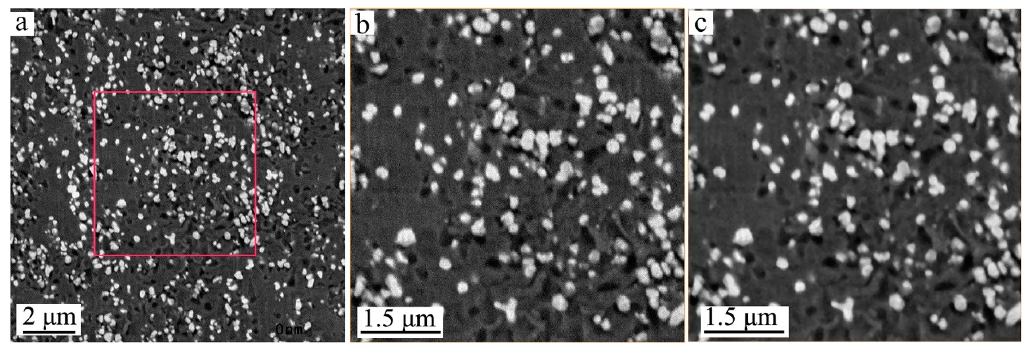
Figure 1a presents the first two-dimensional (2D) BSE micrograph of the waterborne paint sample out of the stack of 100 obtained slices by SBFSEM. The part enclosed by the red square in
Figure 1a was selected for 3D reconstruction and analysis, which is displayed in
Figure 1b.
Figure 1c shows the improved image of
Figure 1b after noise reduction, which is the data used for 3D image segmentation, rendering, and analysis. In accordance to the principle that the brightness of the BSE micrographs scale with the atomic masses of different composites, in the TiO
2 pigmented paint sample, the white particles in the BSE micrographs are identified as TiO
2 particles, all the grey regions within the images are identified as acrylic resin, and the remaining dark parts in the images are identified as voids. At the first glance, the distribution of TiO
2 particles, acrylic resin, and voids within the sample can be clearly seen in these images. The first step to analyzing the 3D image was to align the BSE micrograph slices of the sample, in order to solve the problem of image shifts caused by the possible sample movements and image drifts. Then the threshold segmentation and label analysis were used to perform 3D structural image analysis of the sample. All the data processing above was done via Avizo which is a 3D image processing software package from Thermo Fisher Scientific, Waltham, MA, USA.
Figure 2a shows the 3D image of the measured dry waterborne paint film. In
Figure 2a and the subsequent figures, the translucent grey parts are acrylic resin, the red parts are TiO
2 particles, and the blue parts are voids. From these images, the TiO
2 particles and the voids within the acrylic resin are clearly illustrated in three dimensions.
Figure 2b presents the spatial distribution of the TiO
2 particles only. Although the shape of the TiO
2 particles (see
Figure 2b) look like irregular in three dimensions, the distribution of the TiO
2 particles are relatively homogenous in the cured paint film.
The dispersion of TiO
2 particles in the cured paint film directly affects the performance of the waterborne paint and the consumption of the TiO
2 pigment during paint manufacturing. The distribution of the distances among different TiO
2 particles are clearly presented in
Figure 3a; it can be known that the minimum distance between the particles is 124 nm and about 79% of the distances are between 1.5 µm and 5.5 µm with a nearly Gaussian distribution. This means that the TiO
2 particles have a relatively homogeneous distribution in the cured paint film as shown in
Figure 1 and
Figure 2 as well. The volumes of the single TiO
2 particles range from 2.0 × 10
5 nm
3 to 8.7 × 10
7 nm
3 (see
Figure 3b); they are also listed in
Supplementary Table S1 numerically. These TiO
2 particles have a relatively narrow size distribution, and for about 58% of them, the volume is between 1.0 × 10
6 nm
3 and 1.0 × 10
7 nm
3. The length–width ratios of the TiO
2 particles are presented in
Figure 3c, which shows that the length–width ratios values of all the particles are between 1.3 and 3.9, and 67% of them are between 1.3 and 2.0. This indicates that most of the TiO
2 particles are rice-shaped, and they have a rather unique size range as well which is in a good line with the information obtained from the supplier. Here, the length–width ratio of a particle is the ratio of its maximum Feret diameter against its minimum Feret diameter [
22]. The volume of the voids in the measured dry waterborne paint film are presented in
Figure 3d which shows that the volumes of all the voids are between 1.8 × 10
5 nm
3 and 1.3 × 10
8 nm
3, and 74% of them are between 1.0 × 10
6 nm
3 and 1.0 × 10
8 nm
3. By analyzing the statistical figures in
Supplementary Table S1, it can be obtained that the average volume, length, and length–width ratios of the TiO
2 particles are 8.0 × 10
6 nm
3, 357 nm and 1.9 respectively.
From the 2D images in
Figure 1 and the 3D image in
Figure 2, it can be clearly observed that there are many voids within the cured paint film. In
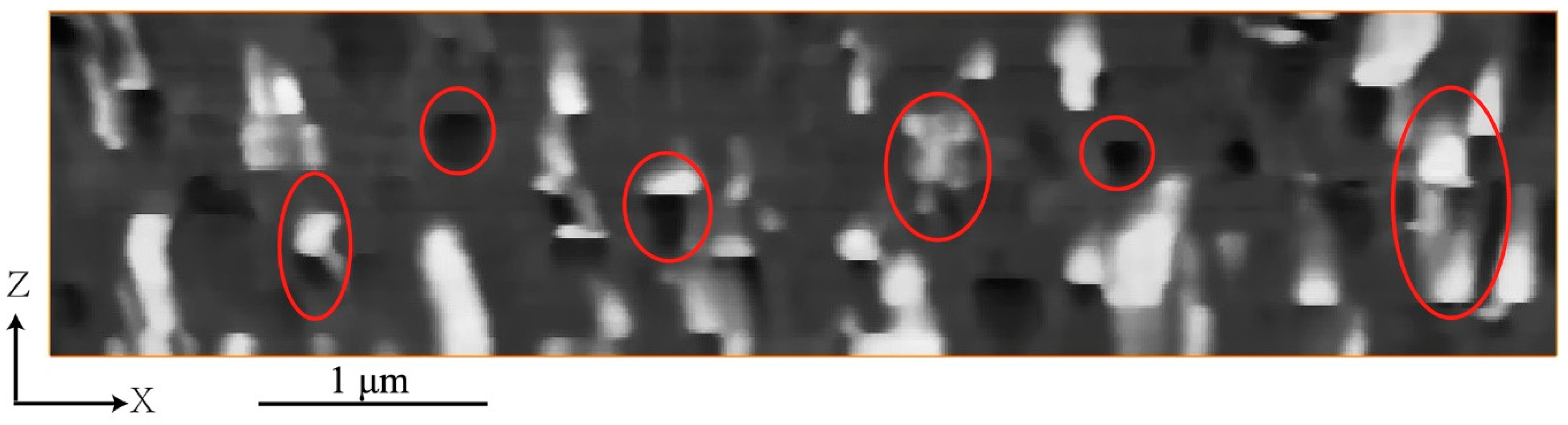
Figure 2a and
Figure 4, it can be observed that the voids are distributed in space in different forms. The XZ plane micrograph shown in
Figure 4 is the image in the direction that is vertical to the XY plane from where the original BSE micrographs were obtained. The 2D image in XZ plane can show the relative position relationship and spatial distribution of voids and particles within the waterborne paint quite directly. From
Figure 4, it can be clearly seen that there are many voids within the paint, some are isolated within the acrylic resin, some are connected with the TiO
2 particles (in up-and-down direction), others are around the TiO
2 particles, as presented in
Figure 1 as well. Even in the raw data of
Figure 4, there is a clear pattern of hemispherical particles on the outer side of the film, which end abruptly with a horizontal boundary and are immediately followed by a similarly shaped hemispherical void. We attribute these features to pigment particles escaping from the sample during the slicing by the diamond knife of the SBFSEM system—they are visible down to their waist, but invisible after the knife passes that point. This supports our following argument that the pigment particles are loosely bound to the paint matrix, probably in a quasi-liquid environment. This result has been reproduced on other paint samples, even well-aged and fully dried examples, suggesting that the surrounding liquid is a long-term configuration of the pigment.
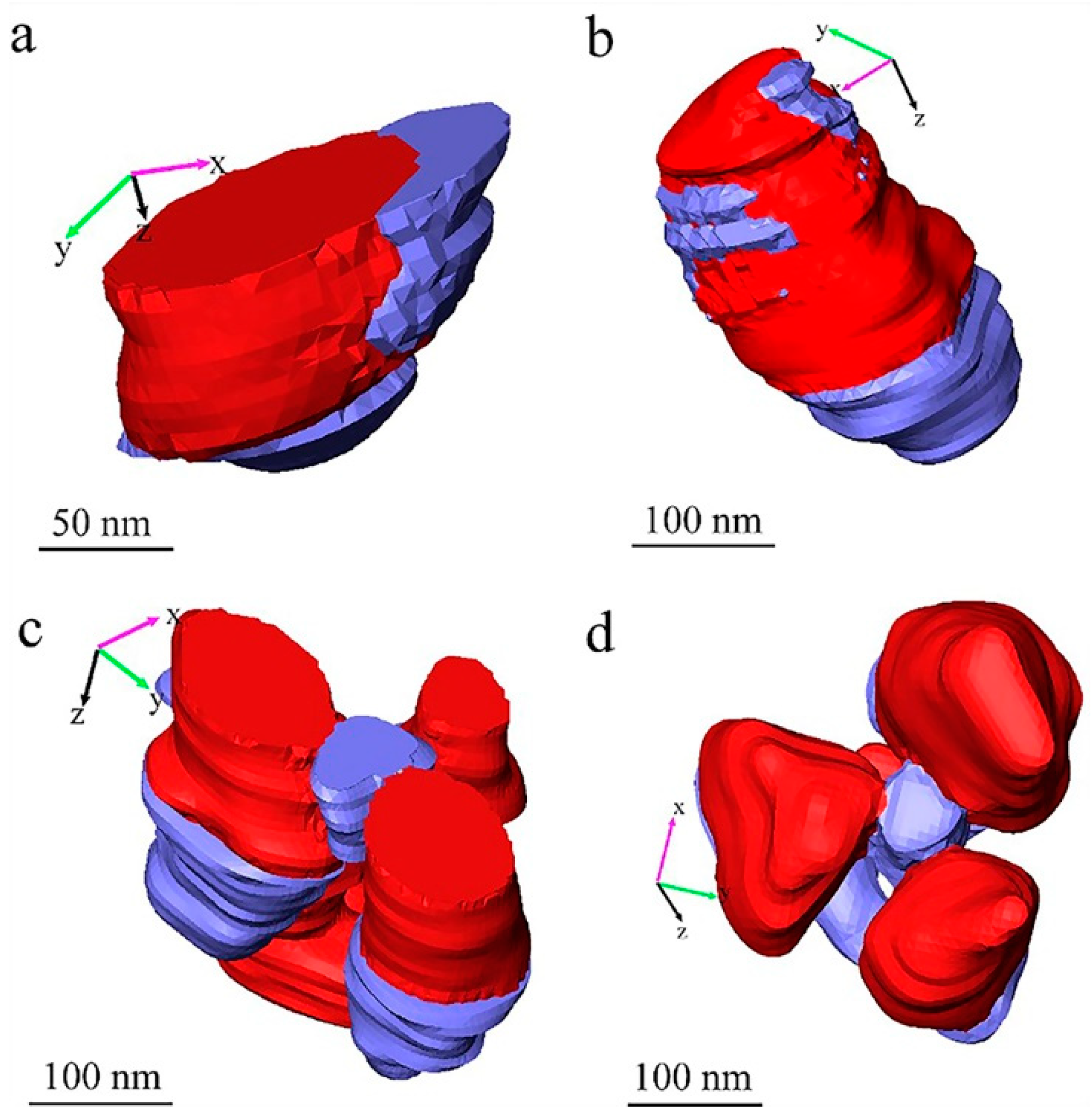
Figure 5 and
Figure 6 show some typical voids in different forms in the measured sample in detail. With combined consideration of the images shown in
Figure 1,
Figure 2 and
Figure 4, we propose that the forms of existence of the voids in the measured paint film can be classified into three types: voids that exist in the paint themselves, voids produced by particle shedding, and voids produced by quasi-liquid phase evaporation (during measurement). All the 3D images with voids in
Figure 5 and
Figure 6 were generated by manual processing using Avizo software (version 9.2, Thermo Fisher Scientific, Waltham, MA, USA), and they are either at the surface or inside the imaged volume of the paint film. As mentioned above, the blue parts are the imaged voids and the red parts are the TiO
2 particles. In these 3D images in
Figure 5 and
Figure 6, the XY plane is the SEM imaging plane and the Z axis is the longitudinal imaging and sectioning direction which is perpendicular to the XY plane.
Figure 5a,b represent the isolated voids in the measured waterborne paint film—the void presented in
Figure 5a is an incomplete void which exists near the surface of the reconstructed volume of the paint film; the void presented in
Figure 5b is an intact void which is inside the paint film. The presence of such voids proves that there are natural voids in the dried paint film. These voids are very likely produced by the solvent evaporation during curing of the applied paint film. These voids play an important role in the appearance of the cured paint surface.
Figure 5c,d represent the voids connected intimately with TiO
2 particles, in which
Figure 5c shows an incomplete TiO
2 particle with the void located near the surface of the reconstructed paint film. From careful observation of the
Supplementary Video S1 and
Figure 5, there is a sharp boundary between the pigment particle and the void, aligned with the cutting direction. We conclude that these voids, seen directly in the raw image of
Figure 4 as well, are produced by pulling the TiO
2 particles out of the paint materials by the diamond knife cutting during SBFSEM imaging. It means that these kind of voids are actually cutting artefacts, not “real” pores in the cured paint film. This feature can be denoted particle “shedding” in this article.
The statistical result from the 3D image segmentation obtained by Avizo gives out that the total volume of the TiO
2 particles, the voids, and the acrylic resin are 5.793 µm
3, 7.693 µm
3 and 49.889 µm
3, respectively, with a total analyzed paint volume of 63.375 µm
3 as shown in
Figure 2a. Since the densities of the TiO
2 particles and the acrylic resin are 4.23 g/cm
3 and 1.05 g/cm
3, the measured weight fraction of the TiO
2 particles is about 31% (density of TiO
2 × volume of TiO
2/(density of TiO
2 × volume of TiO
2 + density of acrylic resin × volume of acrylic resin)), which is only about four-fifths of the expected 38%. This result also supports our observation of the TiO
2 particles shedding during SBFSEM measurement.
This TiO2 particle shedding was caused by the stiffness difference of the TiO2 pigment particles and the acrylic resin matrix and the loose of adhesion between these two materials during the sample’s constant exposure under electron beam illumination and continual mechanical cutting by the diamond knife. The electron beam illumination could break the chemical and/or physical bonding between the TiO2 pigment particles and the acrylic resin under the help from the electron-matter interactions and the vacuum environment in the SEM chamber, and then cause the matrix material lose adhesion with the pigment particles. With the help of the significant difference in the stiffness of these two materials, once the remaining parts of the TiO2 particles in the matrix materials became small enough and were disturbed by the external force from diamond knife cutting, the remaining parts of the TiO2 particles would then fall out of the acrylic resin matrix of the cured paint.
Figure 6 presents the third type of void, which are the voids around TiO
2 particles.
Figure 6a,c show the voids (in blue) near the surface of the measured volume of paint film;
Figure 6b,d show the voids in the measured volume of paint film. In most of these cases in
Figure 6, the TiO
2 particles are finally falling out of the matrix materials, and then the second type of voids, the voids produced by particle shedding, are generated as well, as shown in all the examples displayed in
Figure 6. Especially, in cases of (tiny) clusters of TiO
2 particles as shown in
Figure 6c,d, they are more likely to have voids around the TiO
2 particles, which can be seen in
Figure 1 as well. Considering the shedding of the TiO
2 particles during the SBFSEM measurement, the formation of these kinds of voids around TiO
2 particles in the cured paint film could be caused by evaporation of the liquid phase or moisture in the cured “dry” paint film. Since the specimen was cut and measured in the high vacuum system, the liquid phase in the specimen can be removed by the vacuum system of SBFSEM. As such, these voids are considered voids produced by quasi-liquid phase evaporation. This phenomenon indicates that, in the dry cured waterborne paint film, the TiO
2 pigment particles are still in a quasi-liquid environment. This could be supported by the rational motion of nanoparticles found in viscous or viscoelastic medium under X-ray illumination [
23] which also indicates the nanoparticles could be in a “non-solid” environment in materials normally considered as “solids”, such as paints [
24]. It can be seen that the quasi-liquid phases in the cured waterborne paint film tend to appear around the TiO
2 particles, especially when the TiO
2 particles clustered. As such, the amount of quasi-liquid phases in the cured paint film would rise with the increase of the amount of TiO
2 particles used and the number of TiO
2 particle clusters. Therefore, as evident, if the clusters of the TiO
2 particles in the cured paint film can be effectively reduced, the quasi-liquid phases or voids in the coating can be effectively reduced as well, and the demand for the TiO
2 particles can also be reduced. Not can this help reduce the manufacturing cost of the paint, it can improve the physical and chemical performance of the cured paint.
From the above discussion, we know that the second type of voids that connected intimately with TiO
2 particles caused by particle shedding should be parts of the corresponding TiO
2 particles connected with them. In order to eliminate the errors caused by this artefact, such as lowering the sizes and volumes of the TiO
2 particles, we added the voxels of these voids to their connected TiO
2 particles in the processed 3D image, i.e. these voids have been corrected and treated as parts of their connected TiO
2 particles in the improved statistical analysis as presented in
Figure 7 and
Figure 8.
In
Figure 7, the processed 3D image, in which the voids caused by particle shedding, were newly rendered as parts of TiO
2 particles connected with them (on the basis of
Figure 2b). The statistical analysis results after adding the voids caused by particle shedding to their connected TiO
2 particles are shown in
Figure 8. The corrected distribution of the distances among different TiO
2 particles are clearly presented in
Figure 8a, it can be known that most of the distances, about 76%, are still between 1.5 µm and 5.5 µm and they have a nearly Gaussian distribution as well, which is almost the same as shown in
Figure 3a. However, the minimum distance between the particles becomes 93 nm, which is shorter than 124 nm before correction. This is caused by the corrected TiO
2 particles that are larger and occupy more spaces in the measured volume. The corrected volumes of the single TiO
2 particles displayed in
Figure 8b range from 2.0 × 10
5 nm
3 to 2.0 × 10
8 nm
3. More than 55% of the measured TiO
2 particles have volumes between 1.0 × 10
6 nm
3 and 1.0 × 10
7 nm
3. The volume of the largest TiO
2 particles (2.0 × 10
8 nm
3) after correction is about twice as that of the largest TiO
2 particles (8.7 × 10
7 nm
3) before correction, which indicates that the largest TiO
2 particles tend to be shed at the half way during the cutting-imaging process by SBFSEM. The corrected length–width ratios of the TiO
2 particles presented in
Figure 8c are between 1.3 and 6.5, and 84% of them are between 1.3 and 2.5. The corrected volume of the voids in the paint presented in
Figure 8d shows that volume of the individual voids is between 1.8 × 10
5 nm
3 and 1.3 × 10
8 nm
3, the same as before correction, but the quantity of voids after correction is about two thirds of that before correction. Yet, there has not been a great change in the volume distribution of the voids after correction. 67% of the voids are between 1.0 × 10
6 nm
3 and 1.0 × 10
8 nm
3, only slightly lower than 74% before correction. It can also be obtained that the average volume, length, and length–width ratios of the corrected TiO
2 particles are 1.2 × 10
7 nm
3, 396 nm, and 2.1 that are larger than 8.0 × 10
6 nm
3, 357 nm, and 1.9 before correction. This can be easily understood because the corrected TiO
2 particles are larger and longer than before.
After correction, the total volume of TiO2 particles increases from 5.793 µm3 to 7.838 µm3, so the measured weight fraction of the TiO2 particles increases from 31% to 38.3%, which is very close to the expected 38%. This result turns out again supporting that the TiO2 particles are shedding during SBFSEM measurement, and SBFSEM is proven to be a reliable tool for 3D nano-structure investigation for materials.

 ,
, 


