Analysis of Cement Deterioration in Outdoor High-Voltage Insulator


Abstract
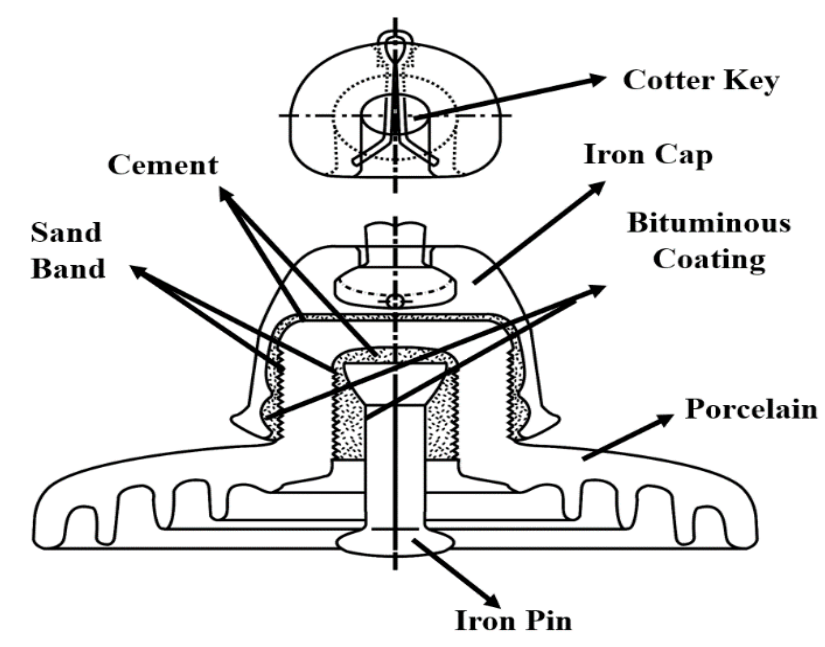
1. Introduction
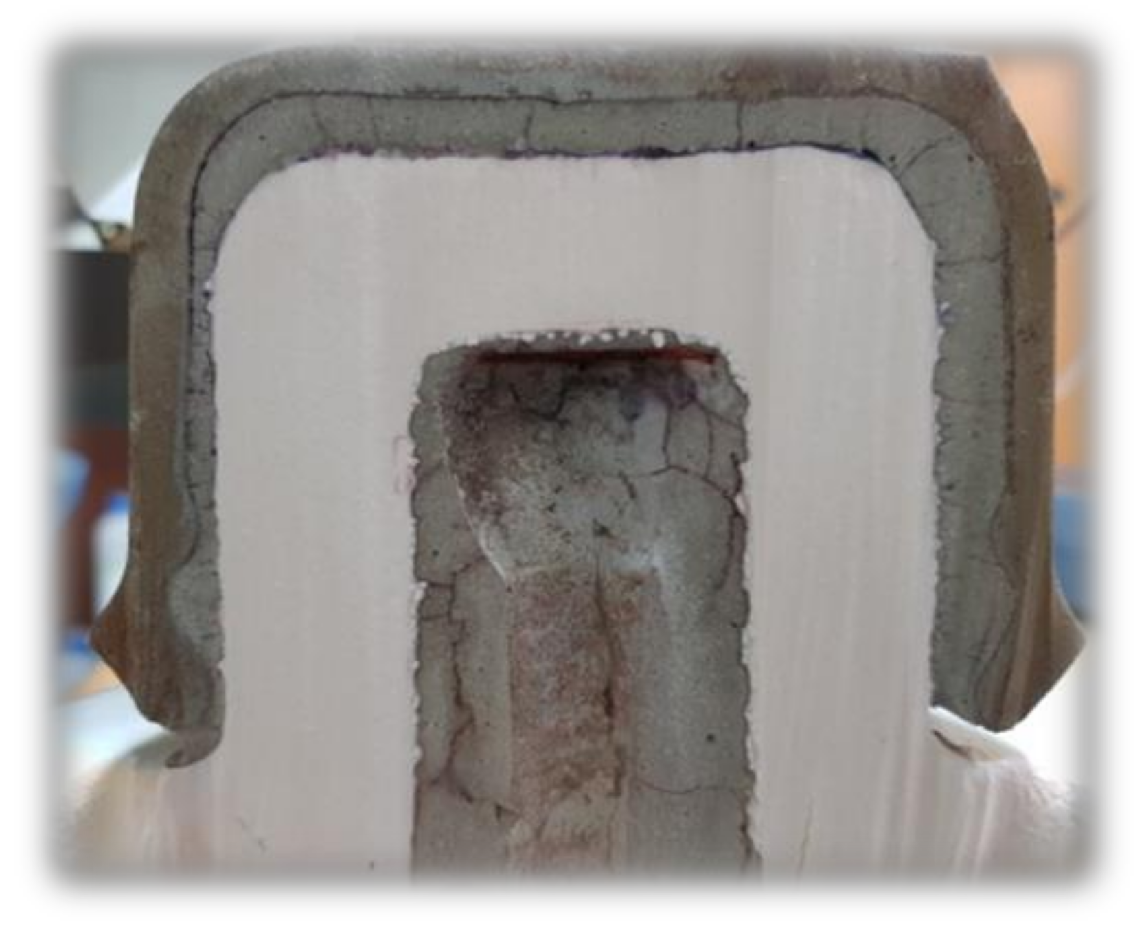
2. Experiments
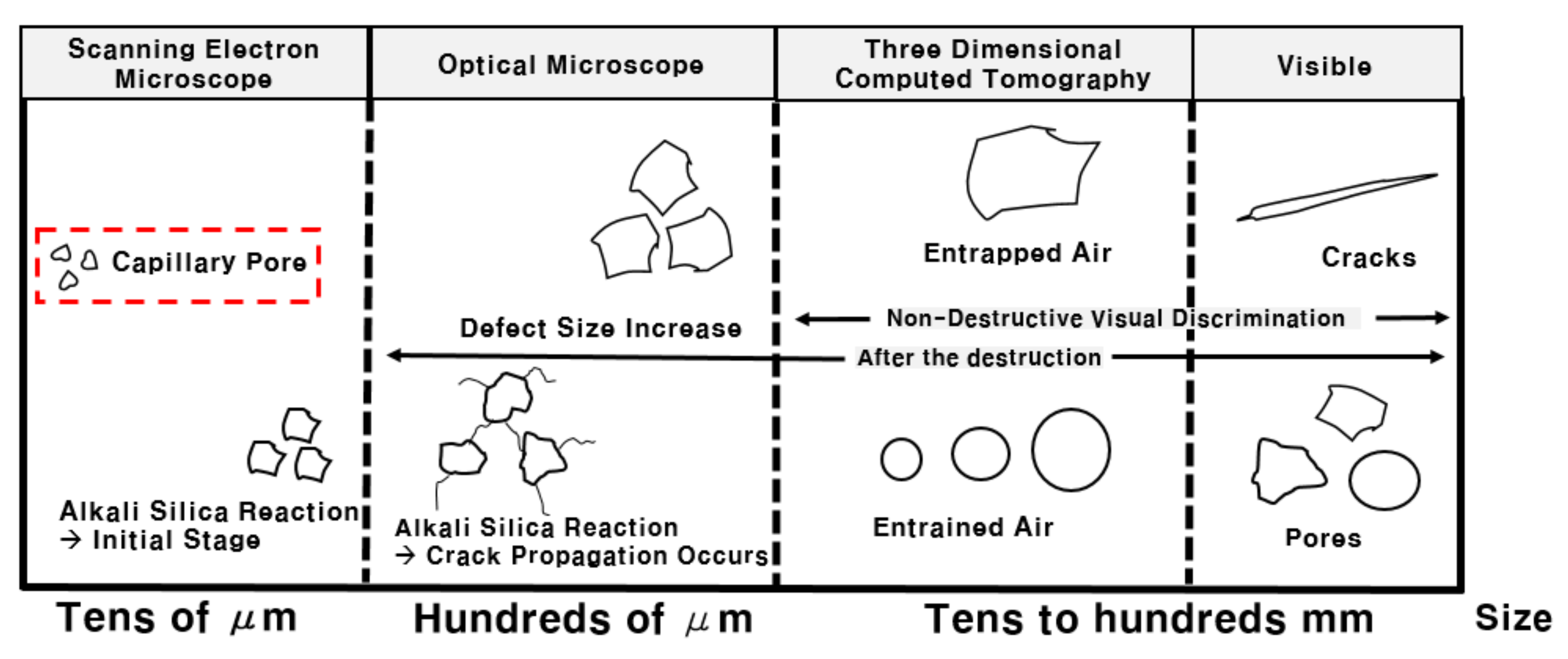
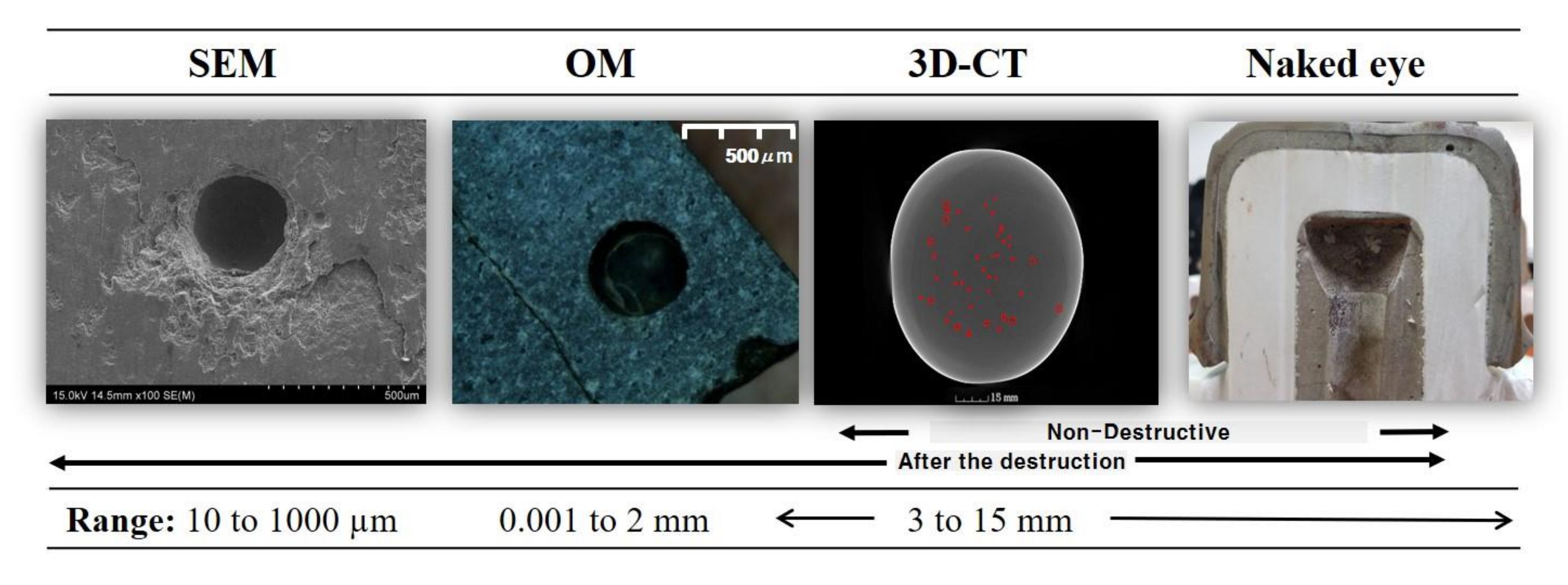
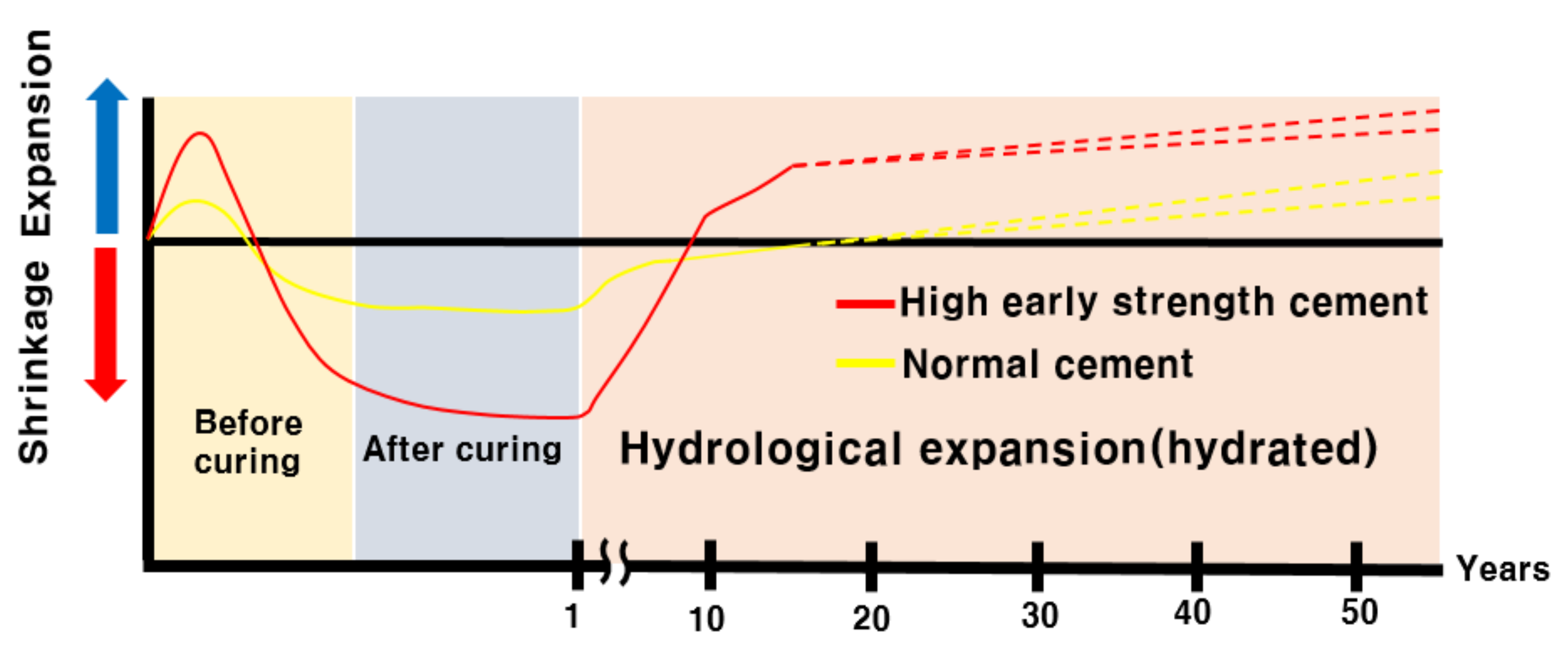
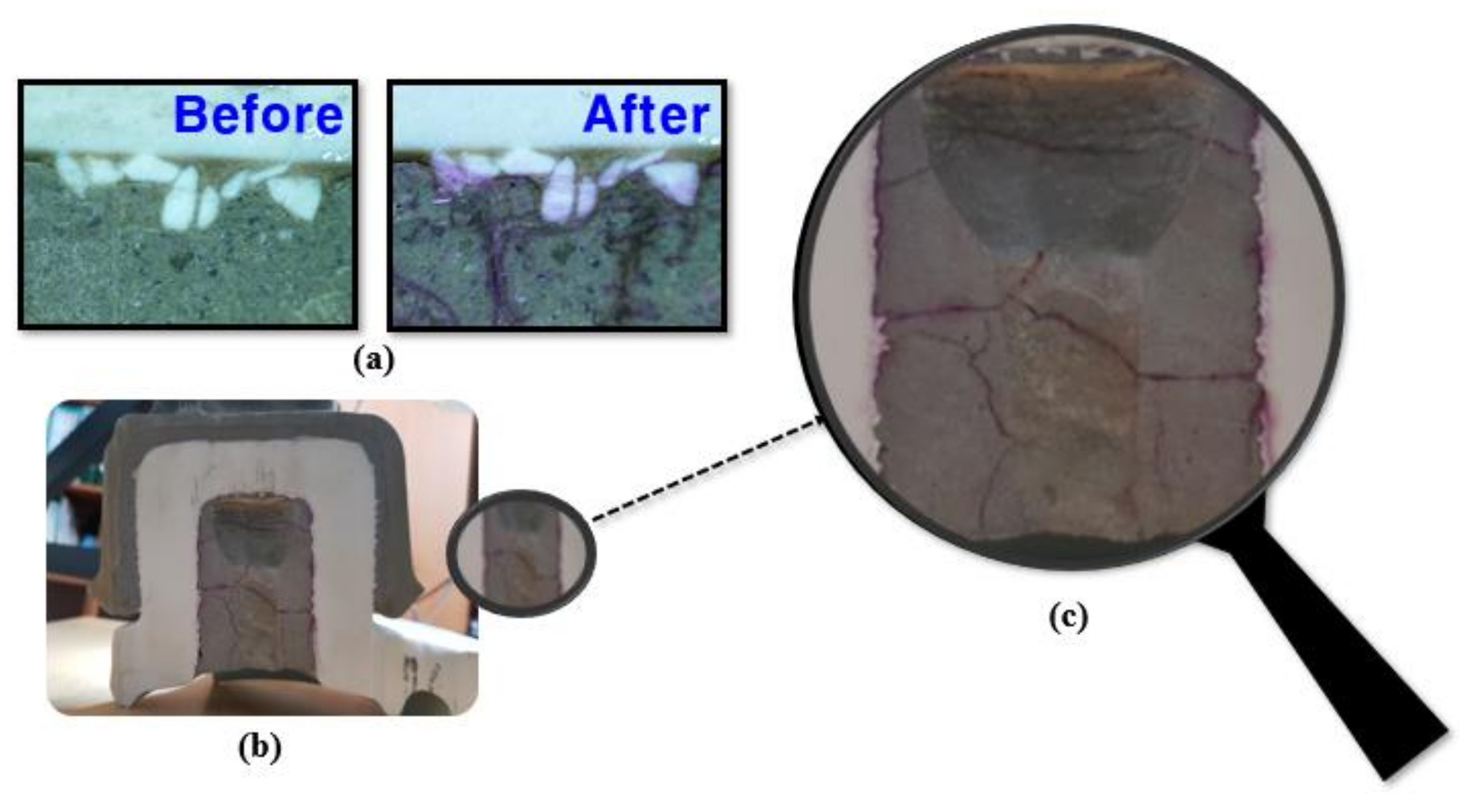
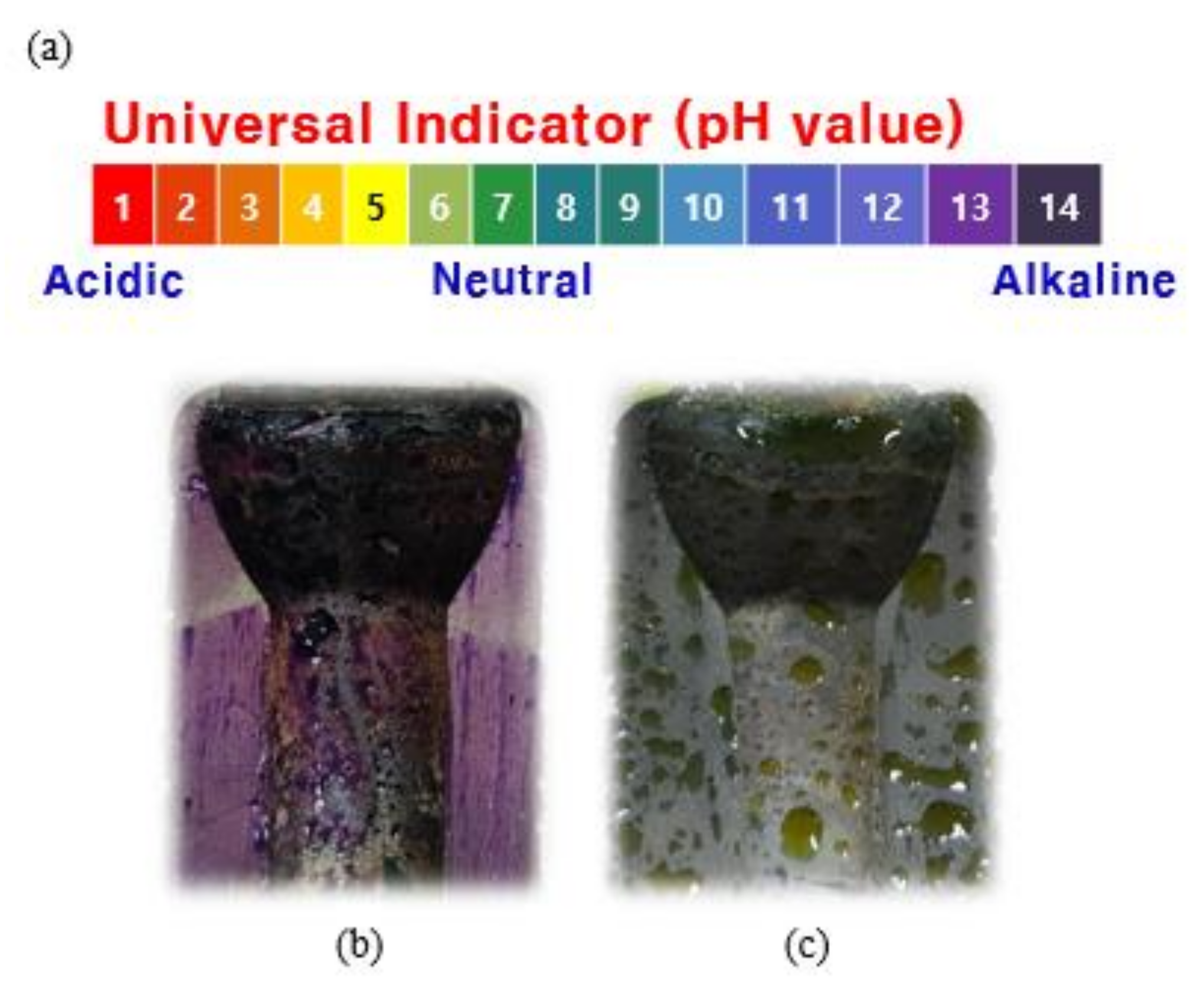
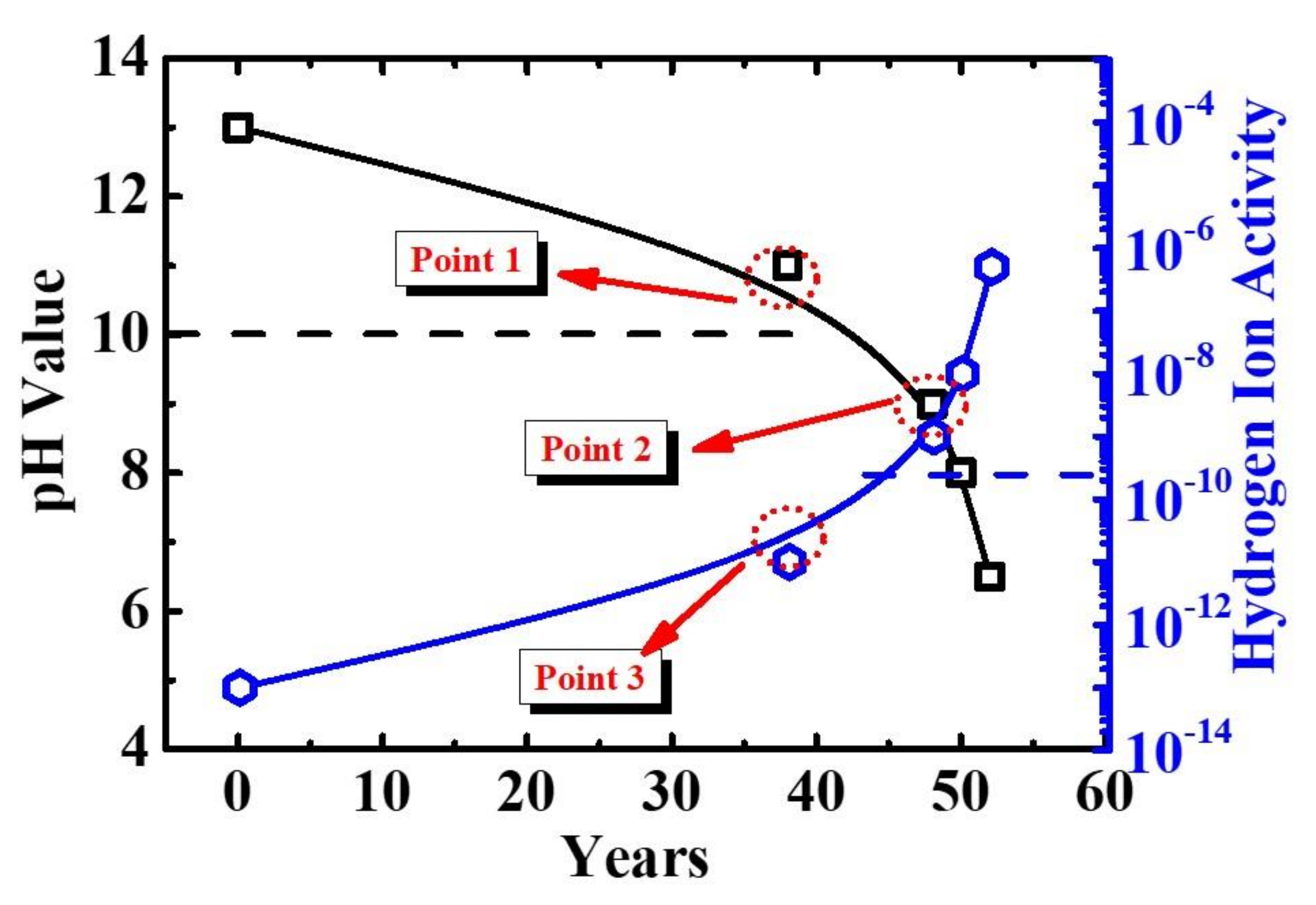
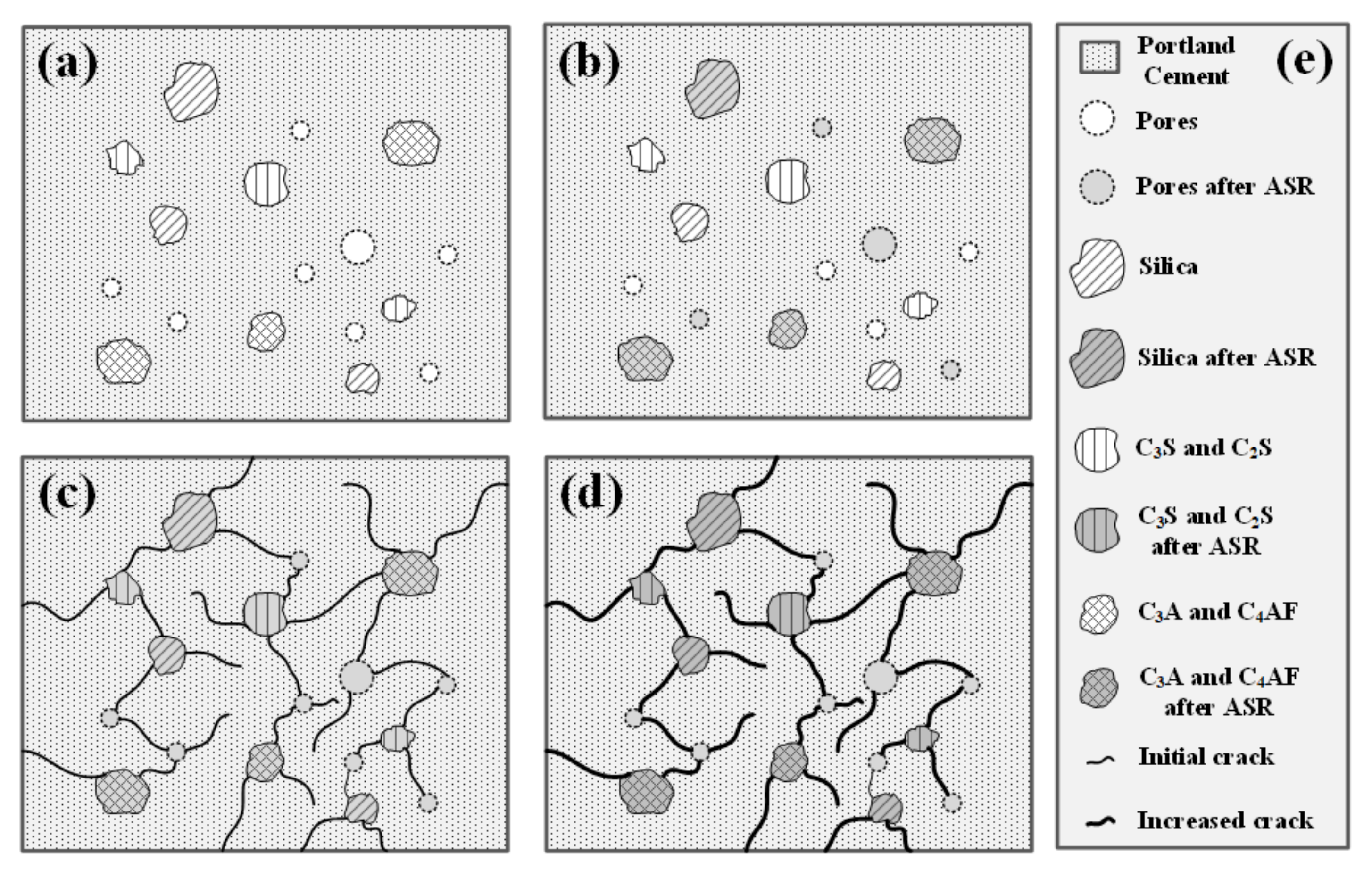
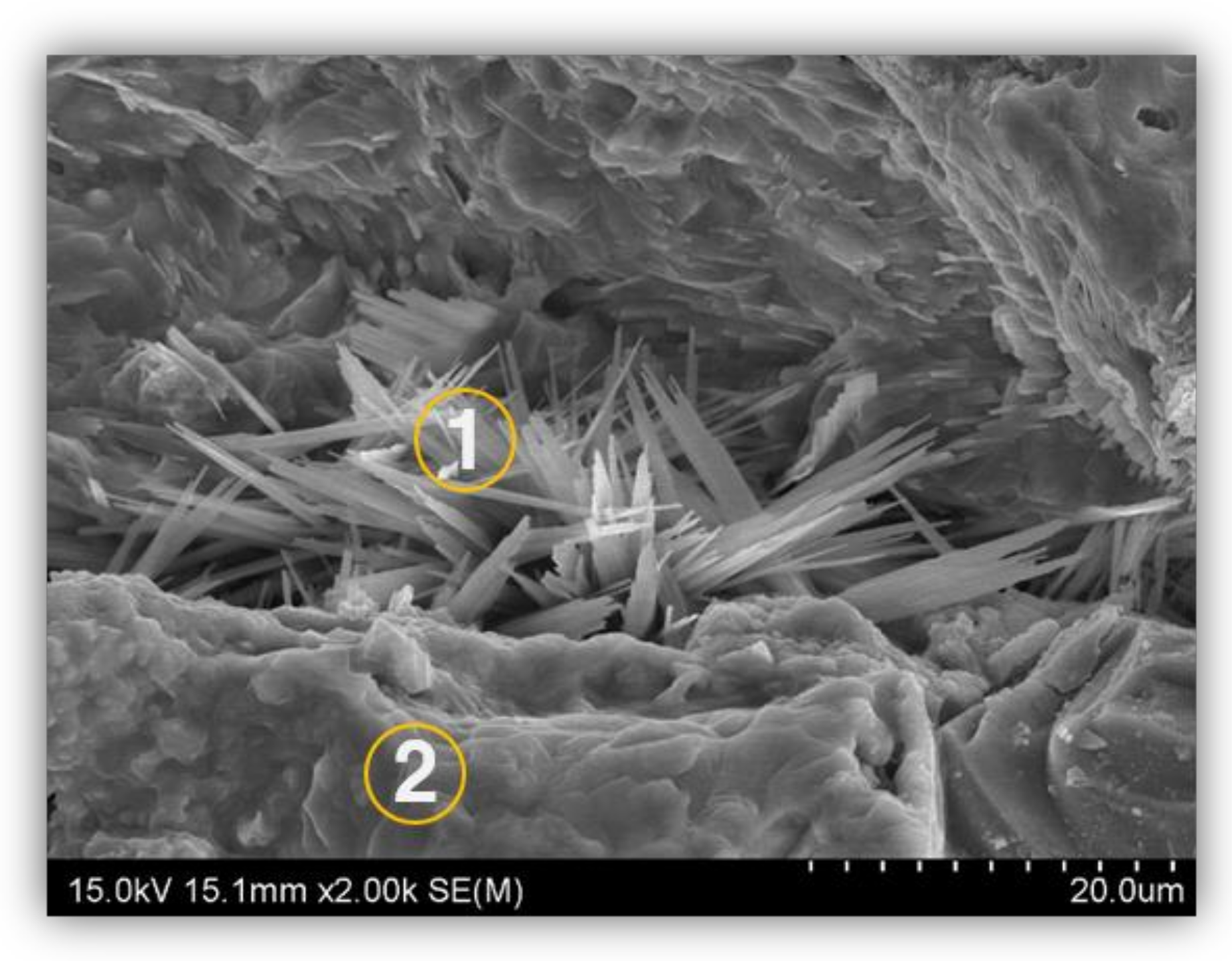
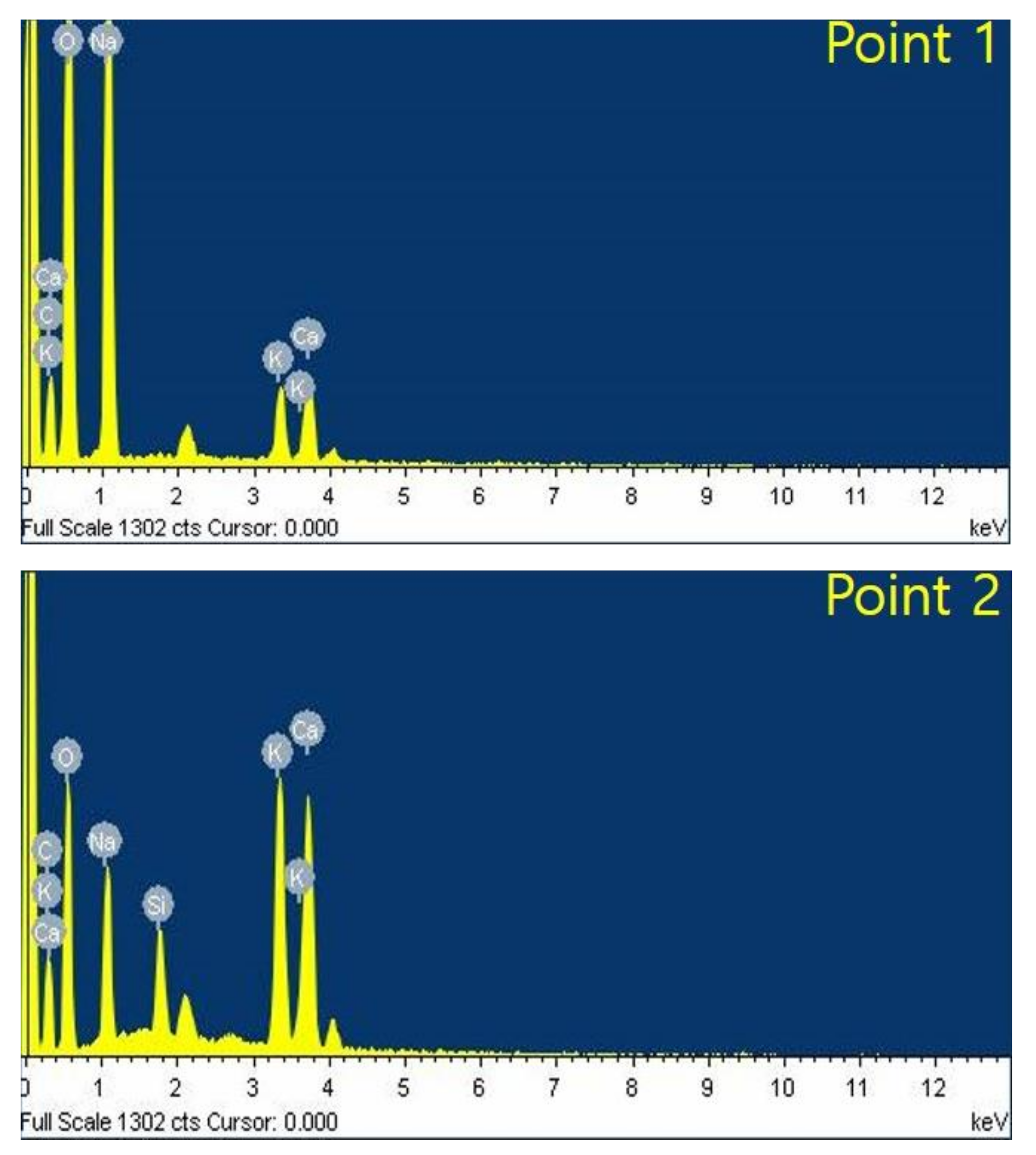
3. Results and Discussion
4. Conclusions
Author Contributions
Funding
Conflicts of Interest
References
- Mills, B. Porcelain Insulators and How They Grew; Library of Congress: Leroy, NY, USA, 1970; Catalog No. 78-146302; Published privately. [Google Scholar]
- Rosenthal, E. Insulator Glazes. Nature 1942, 150, 771–772. [Google Scholar]
- Mishra, A.P.; Gorur, R.S.; Venkataraman, S. Evaluation of Porcelain and Toughened Glass Suspension Insulators Removed from Service. IEEE Trans. Dielectr. Electr. Insul. 2008, 15, 467–475. [Google Scholar] [CrossRef]
- Li, J.; Sun, C.; Sima, W.; Yang, Q.; Hu, J. Contamination Level Prediction of Insulators Based on the Characteristics of Leakage Current. IEEE Trans. Power Del. 2010, 25, 417–424. [Google Scholar]
- Duncan Glover, J.; Sama, M.S.; Overbye, T. Power System Analysis and Design; Cengage Learning: Belmont, CA, USA, 1987. [Google Scholar]
- Jiang, X.; Yuan, J.; Shu, L.; Zhang, Z.; Hu, J.; Mao, F. Comparison of DC Pollution Flashover Performances of Various Types of Porcelain, Glass, and Composite Insulators. IEEE Trans. Power Del. 2008, 23, 1183–1190. [Google Scholar] [CrossRef]
- Jiang, X.; Chen, L.; Zhang, Z.; Sun, C.; Hu, J. Equivalence of Influence of Pollution Simulating Methods on DC Flashover Stress of Ice-Covered Insulators. IEEE Trans. Power Del. 2010, 25, 2113–2120. [Google Scholar] [CrossRef]
- Liu, L.; Wang, L.; Guo, C.; Mei, H.; Zhao, C. Detecting Defects in Porcelain Post insulator Coated with Room Temperature Vulcanized Silicone Rubber by Pulsed Thermography. IEEE Trans. Instrum. Meas. 2019, 68, 225–233. [Google Scholar] [CrossRef]
- Ale-Emran, S.M.; Farzaneh, M. Experimental Design of Booster-Shed Parameters for Post Insulators under Heavy Icing Conditions. IEEE Trans. Power Del. 2015, 30, 488–496. [Google Scholar] [CrossRef]
- Cherney, E.A.; Chair, A.; Baker, C.; Kuffel, J.; Lodi, Z.; Phillips, A.; Powell, D.G.; Stewart, G.A. Evaluation of and Replacement Strategies for Aged High Voltage Porcelain Suspension-Type Insulators. IEEE Trans. Power Del. 2014, 29, 275–282. [Google Scholar] [CrossRef]
- American Standards for Wet-Process Porcelain Insulators (Suspension Type), ASA Standard C29.2–1955.
- Golewski, G.L. Effect of curing time on the fracture toughness of fly ash concrete composites. Compos. Struct. 2018, 185, 105–112. [Google Scholar] [CrossRef]
- Hong, H.M.; Lee, Y.; Lee, H.; Kim, S. A Colorimetric Multifunctional Sensing Method for Structural-Durability-Health Monitoring Systems. Adv. Mater. 2019, 31, 1807552. [Google Scholar]
- Andrejkoviova, S.; Alves, C.; Velosa, A.; Rocha, F. Bentonite as a natural additive for lime and lime-metakaolin mortars used for restoration of adobe buildings. Cem. Concr. Compos. 2015, 60, 99–110. [Google Scholar] [CrossRef]
- Choi, J.; Lee, Y.; Kim, Y.Y.; Lee, B.Y. Image-processing technique to detect carbonation regions of concrete sprayed with a phenolphthalein solution. Const. Build. Mater. 2017, 154, 451–461. [Google Scholar] [CrossRef]
- Afroz, M.; Patnaikuni, I.; Venkatesan, S. Chemical durability and performance of modified basalt fiber in concrete medium. Const. Build. Mater. 2017, 154, 191–203. [Google Scholar] [CrossRef]
- Gutberlet, T.; Hilbig, H.; Beddoe, R.E. Acid attack on hydrated cement-Effect of mineral acids on the degradation process. Cem. Concr. Res. 2015, 74, 35–43. [Google Scholar] [CrossRef]
- Kim, T.; Jeon, S.; Lee, Y.-J.; Yi, J.; Choi, I.-H.; Son, J.-A.; Choi, C.-W. Three-Dimensional Computed Tomography and Composition Analysis of Porcelain Insulators for 154 kV Power Transmission Lines. IEEE Trans. Dielectr. Electr. Insul. 2019, 26, 115–119. [Google Scholar] [CrossRef]
- Mahmoudi, J.; Moussavi, S.Z.; Naderi, P. Partial Discharge Diagnosis of Ceramic Pin Insulators Considering Cost-worth Analysis: Case Study in a Medium Voltage Feeder. IEEE Trans. Dielectr. Electr. Insul. 2017, 24, 2493–2502. [Google Scholar] [CrossRef]
- Morin, V.; Termkhajornkit, P.; Huet, B.; Pham, G. Impact of quantity of anhydrite, water to binder ratio, fineness on kinetics and phase assemblage of belite-ye’elimite-ferrite cement. Cem. Concr. Res. 2017, 99, 8–17. [Google Scholar] [CrossRef]
- Stephan, D.; Mallmann, R.; Knofel, D.; Hardtl, R. High intakes of Cr, Ni, and Zn in Clinker Part I. Influence on burning process and formation of phases. Cem. Concr. Res. 1999, 29, 1949–1957. [Google Scholar] [CrossRef]
- Mollah, M.Y.A.; Palta, P.; Hess, T.R.; Vempati, R.K.; Cocke, D.L. Chemical and Physical Effects of Sodium Lignosulfonate Superplasticizer on the Hydration of Portland Cement and Solidification/Stabilization Consequences. Cem. Concr. Res. 1995, 25, 671–682. [Google Scholar]
- Shaw, S.; Clark, S.M.; Henderson, C.M.B. Hydrothermal formation of the calcium silicate hydrates, tobermorite (Ca5Si6O16(OH)24H2O) and xonotlite (Ca6Si6O17(OH)2): An in situ synchrotron study. Chem.Geol. 2000, 167, 129–140. [Google Scholar] [CrossRef]
- Jennings, H.M. A Model for the Microstructure of Calcium Silicate Hydrate in Cement Paste. Cem. Concr. Res. 2000, 30, 101–116. [Google Scholar] [CrossRef]
- Richardson, I.G. The Calcium Silicate Hydrates. Cem. Concr. Res. 2008, 38, 137–158. [Google Scholar] [CrossRef]
- Bensted, J. Hydration of Portland Cement. Adv. Cem. Technol. 1983, 307–347. [Google Scholar] [CrossRef]
- Mehta, P.K. Effect of Lime on Hydration of Pastes Containing Gypsum and Calcium Aluminates or Calcium Sulfoaluminate. J. Am. Ceram. Soc. 1973, 56, 315–319. [Google Scholar] [CrossRef]
- Hargis, C.W.; Kirchheim, A.P.; Monteiro, P.J.M.; Gartner, E.M. Early Age Hydration of Calcium Sulfoaluminate (Synthetic Yeelimite, C4A3S) in the Presence of Gypsum and Varying Amounts of Calcium Hydroxide. Cem. Concr. Res. 2013, 48, 105–115. [Google Scholar] [CrossRef]
- Quennoz, A.; Scrivener, K.L. Hydration of C3A-Gypsum Systems. Cem. Concr. Res. 2012, 42, 1032–1041. [Google Scholar] [CrossRef]
- Bentza, D.P.; Geikerb, M.R.; Hansenb, K.K. Shrinkage-reducing admixtures and early-age desiccation in cement pastes and mortars. Cem. Concr. Res. 2001, 31, 1075–1085. [Google Scholar] [CrossRef]
- Kanna, V.; Olson, R.A.; Jennings, H.M. Effect of shrinkage and moisture content on the physical characteristics of blended cement mortars. Cem. Concr. Res. 1998, 28, 1467–1477. [Google Scholar] [CrossRef]
- Galle, C. Effect of drying on cement-based materials pore structure as identified by mercury intrusion porosimetry: A comparative study between oven-, vacuum-, and freeze-drying. Cem. Concr. Res. 2001, 31, 1467–1477. [Google Scholar] [CrossRef]
- Aligizaki, K.K. Pore Structure of Cement-Based Materials; Modern Concrete Technology 12; CRC Press: Boca Raton, FL, USA, 2006. [Google Scholar]
- Han, L.; Okamoto, A.; Fukushima, M.; Okiji, T. Enamel Micro-Cracks Produced around Restorations with Flowable Composites. Dent. Mater. J. 2005, 24, 83–91. [Google Scholar] [CrossRef]
- Al-Saleh, M.; El-Mowafy, O.; Tam, L.; Fenton, A. Microleakage of posterior composite restorations lined with self-adhesive resin cements. Oper. Dent. 2010, 35, 556–563. [Google Scholar] [CrossRef] [PubMed]
- Diamond, S. A Review of Alkali-Silica Reaction and Expansion Mechanisms 1. Alkalies in Cements and in Concrete Pore Solutions. Cem. Concr. Res. 1975, 5, 329–345. [Google Scholar] [CrossRef]
- Matos, A.M.; Sousa-Coutinho, J. Durability of Mortar using Waste Glass Powder as Cement Replacement. Const. Build. Mater. 2012, 36, 205–215. [Google Scholar] [CrossRef]
- Cebeci, O.Z. Pore Structure of Air-Entrained Hardened Cement Paste. Cem. Concr. Res. 1981, 11, 257–265. [Google Scholar] [CrossRef]
- Espinosa, R.M.; Franke, L. Influence of the Age and Drying Process on Pore Structure and Sorption Isotherms of Hardened Cement Paste. Cem. Concr. Res. 2006, 36, 1969–1984. [Google Scholar] [CrossRef]
- Jensen, O.M.; Hansen, P.F. Water-Entrained Cement-Based Materials I. Principles and Theoretical Background. Cem. Concr. Res. 2001, 31, 647–654. [Google Scholar] [CrossRef]
- Hou, P.; Kawashima, S.; Kong, D.; Corr, D.J.; Qian, J.; Shah, S.P. Modification effects of colloidal nanoSiO2 on cement hydration and its gel property. Compos. Part B Eng. 2013, 34, 440–448. [Google Scholar] [CrossRef]
- Min, D.; Tang, M. Formation and Expansion of Ettringite Crystals. Cem. Concr. Res. 1994, 24, 119–126. [Google Scholar] [CrossRef]
- Kolb, D. The pH Concept. J. Chem. Educ. 1979, 56, 49–53. [Google Scholar] [CrossRef]
- Chatterji, S. Chemistry of Alkali-Silica Reaction and Testing of Aggregates. Cem. Concr. Compos. 2005, 27, 778–795. [Google Scholar] [CrossRef]
- Wang, H.; Gillott, J.E. Mechanism of Alkali-Silica Reaction and the Significance of Calcium Hydroxide. Cem. Concr. Res. 1991, 21, 647–654. [Google Scholar] [CrossRef]
- Rajabipour, F.; Giannini, E.; Dunant, C.; Ideker, J.H.; Thomas, M.D.A. Alkali–Silica Reaction: Current Understanding of the Reaction Mechanisms and the Knowledge Gaps. Cem. Concr. Res. 2015, 75, 130–146. [Google Scholar] [CrossRef]
- Thomas, M.; Fournier, B.; Folliard, K.; Ideker, K.; Shehata, M. Test Methods for Evaluating Preventive Measures for Controlling Expansion due to Alkali–Silica Reaction in Concrete. Cem. Concr. Res. 2006, 36, 1842–1856. [Google Scholar] [CrossRef]
- Beaudoin, J.J.; Ramachandran, V.S. A new Perspective on the Hydration Characteristics of Cement Phases. Cem. Concr. Res. 1992, 22, 689–694. [Google Scholar] [CrossRef]
- Andersen, M.D.; Jakobsen, H.J.; Skibsted, J. Characterization of White Portland Cement Hydration and the C-S-H Structure in the Presence of Sodium Aluminate by 27Al and 29Si MAS NMR Spectroscopy. Cem. Concr. Res. 2004, 34, 857–868. [Google Scholar] [CrossRef]
- Karim, M.R.A.; Zain, M.F.M.; Jamil, M.; Lai, F.C. Fabrication of a Non-Cement Binder using Slag, Palm Oil Fuel Ash and Rice Husk Ash with Sodium Hydroxide. Constr. Build. Mater. 2013, 49, 894–902. [Google Scholar] [CrossRef]


| Effect by pH value | pH Value | Effect |
| Higher than 10 | Difficult to corrode metal | |
| Between 4 and 10 | High probability of metal corrosion | |
| Between 1 and 3 | Metal is easily corroded |
| Properties | pH | H+Activity | OH−Activity |
|---|---|---|---|
| Acid | 0 | 1 × 10−0 | 1 × 10⁻¹⁴ |
| 1 | 1 × 10⁻¹ | 1 × 10⁻¹³ | |
| 2 | 1 × 10⁻² | 1 × 10⁻¹² | |
| 3 | 1 × 10⁻³ | 1 × 10⁻¹¹ | |
| 4 | 1 × 10⁻⁴ | 1 × 10⁻¹⁰ | |
| Neutral | 5 | 1 × 10⁻⁵ | 1 × 10⁻⁹ |
| 6 | 1 × 10⁻⁶ | 1 × 10⁻⁸ | |
| 7 | 1 × 10⁻⁷ | 1 × 10⁻⁷ | |
| Base | 8 | 1 × 10⁻⁸ | 1 × 10⁻⁶ |
| 9 | 1 × 10⁻⁹ | 1 × 10⁻⁵ | |
| 10 | 1 × 10⁻¹⁰ | 1 × 10⁻⁴ | |
| 11 | 1 × 10⁻¹¹ | 1 × 10⁻³ | |
| 12 | 1 × 10⁻¹² | 1 × 10⁻² | |
| 13 | 1 × 10⁻¹³ | 1 × 10⁻¹ | |
| 14 | 1 × 10⁻¹⁴ | 1 × 10−0 |
| C | O | Na | Si | K | Ca | |
|---|---|---|---|---|---|---|
| 1 | 19.52 | 59.96 | 17.02 | - | 1.5 | 2 |
| 2 | 19.88 | 54.59 | 7.14 | 2.71 | 7.49 | 8.19 |
© 2019 by the authors. Licensee MDPI, Basel, Switzerland. This article is an open access article distributed under the terms and conditions of the Creative Commons Attribution (CC BY) license (http://creativecommons.org/licenses/by/4.0/).
Share and Cite
Kim, T.; Sanyal, S.; Koo, J.-B.; Son, J.-A.; Choi, I.-H.; Yi, J. Analysis of Cement Deterioration in Outdoor High-Voltage Insulator. Materials 2019, 12, 4201. https://doi.org/10.3390/ma12244201
Kim T, Sanyal S, Koo J-B, Son J-A, Choi I-H, Yi J. Analysis of Cement Deterioration in Outdoor High-Voltage Insulator. Materials. 2019; 12(24):4201. https://doi.org/10.3390/ma12244201
Chicago/Turabian StyleKim, Taeyong, Simpy Sanyal, Ja-Bin Koo, Ju-Am Son, In-Hyuk Choi, and Junsin Yi. 2019. "Analysis of Cement Deterioration in Outdoor High-Voltage Insulator" Materials 12, no. 24: 4201. https://doi.org/10.3390/ma12244201
APA StyleKim, T., Sanyal, S., Koo, J.-B., Son, J.-A., Choi, I.-H., & Yi, J. (2019). Analysis of Cement Deterioration in Outdoor High-Voltage Insulator. Materials, 12(24), 4201. https://doi.org/10.3390/ma12244201