Analysis of Stresses in a Tapered Roller Bearing Using Three-Dimensional Photoelasticity and Stereolithography

 ,
,
Abstract
1. Introduction
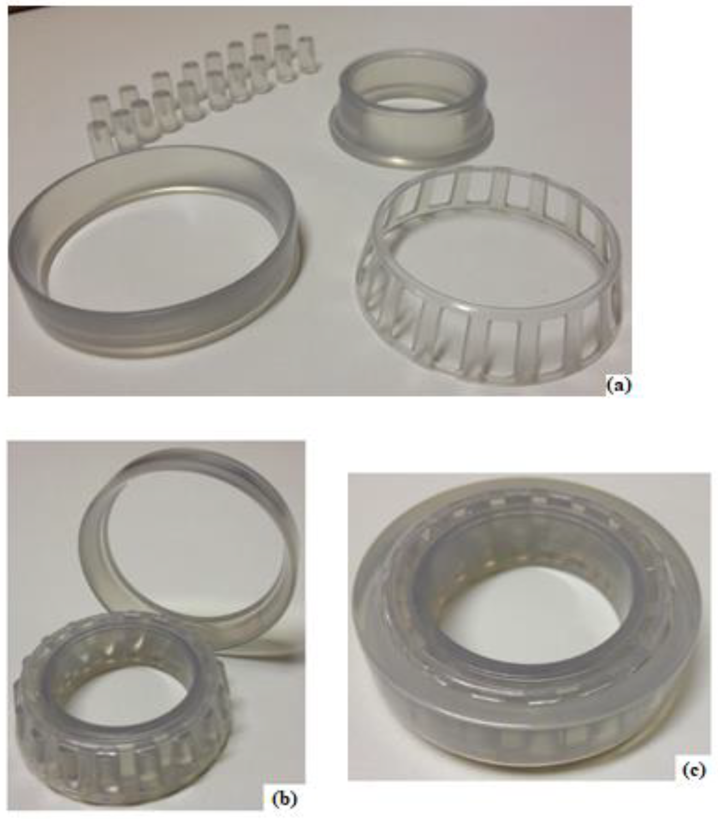
2. Stereolithography and Photoelasticity
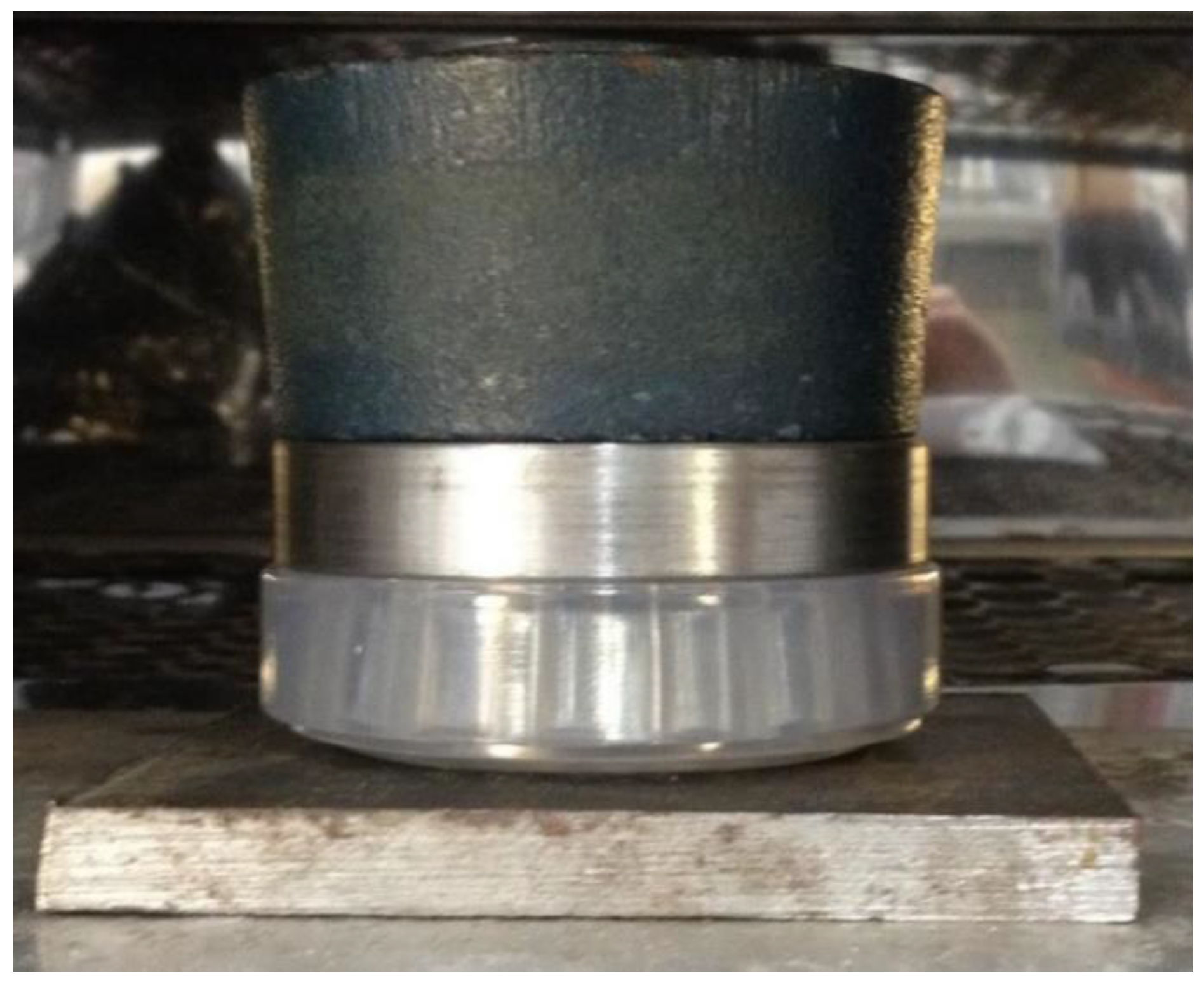
3. Methodology
- (a)
- elements used: C3D4 (linear tetrahedral) for the cage and tapered rollers (due to their geometric complexities), and C3D8 (linear hexahedral) for the outer and inner rings,
- (b)
- average element size: 0.5 mm,
- (c)
- number of nodes: 207,136,
- (d)
- number of elements: 360,230,
- (e)
- type of analysis: nonlinear static.
4. Results and Discussion
- (a)
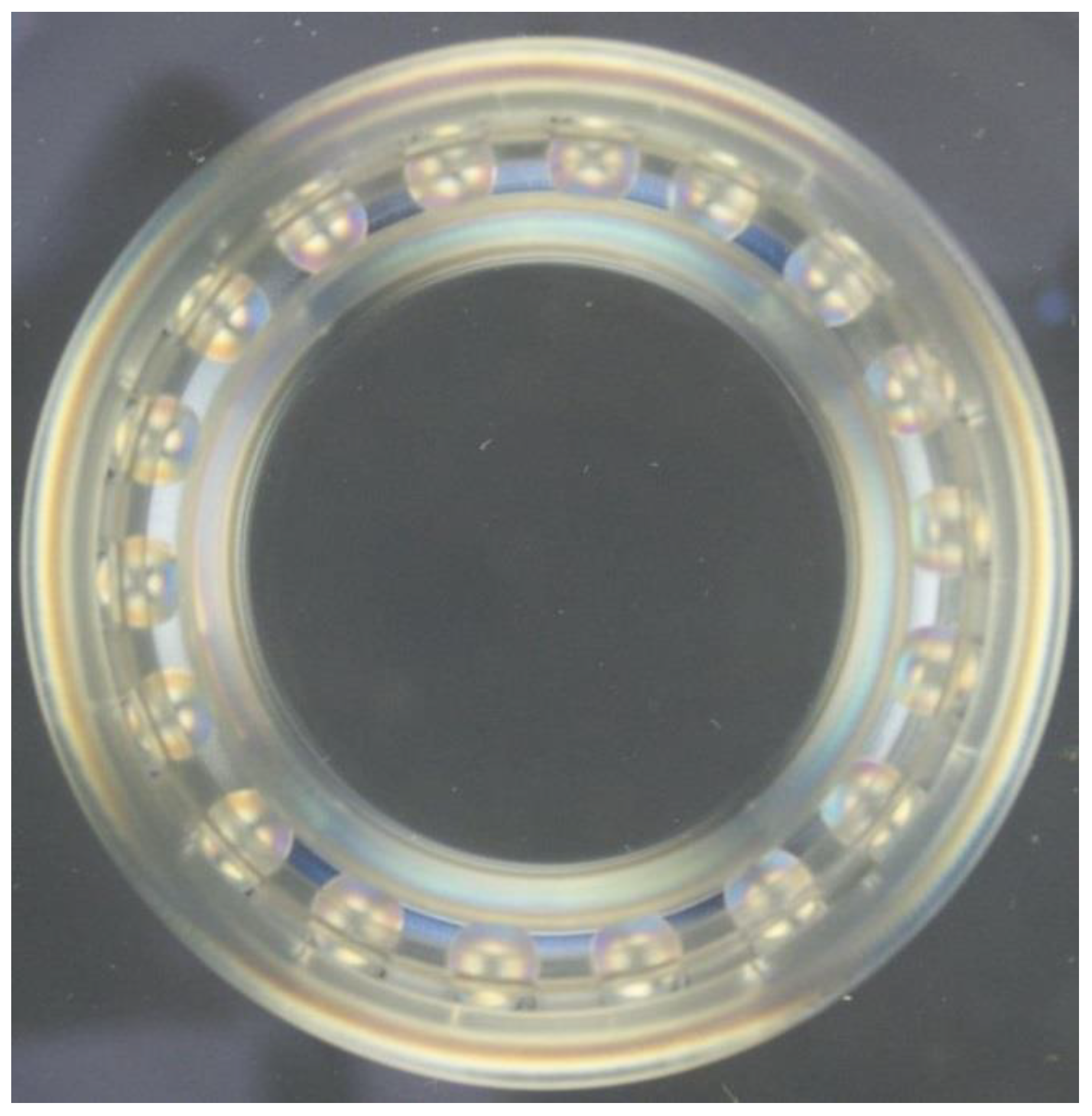
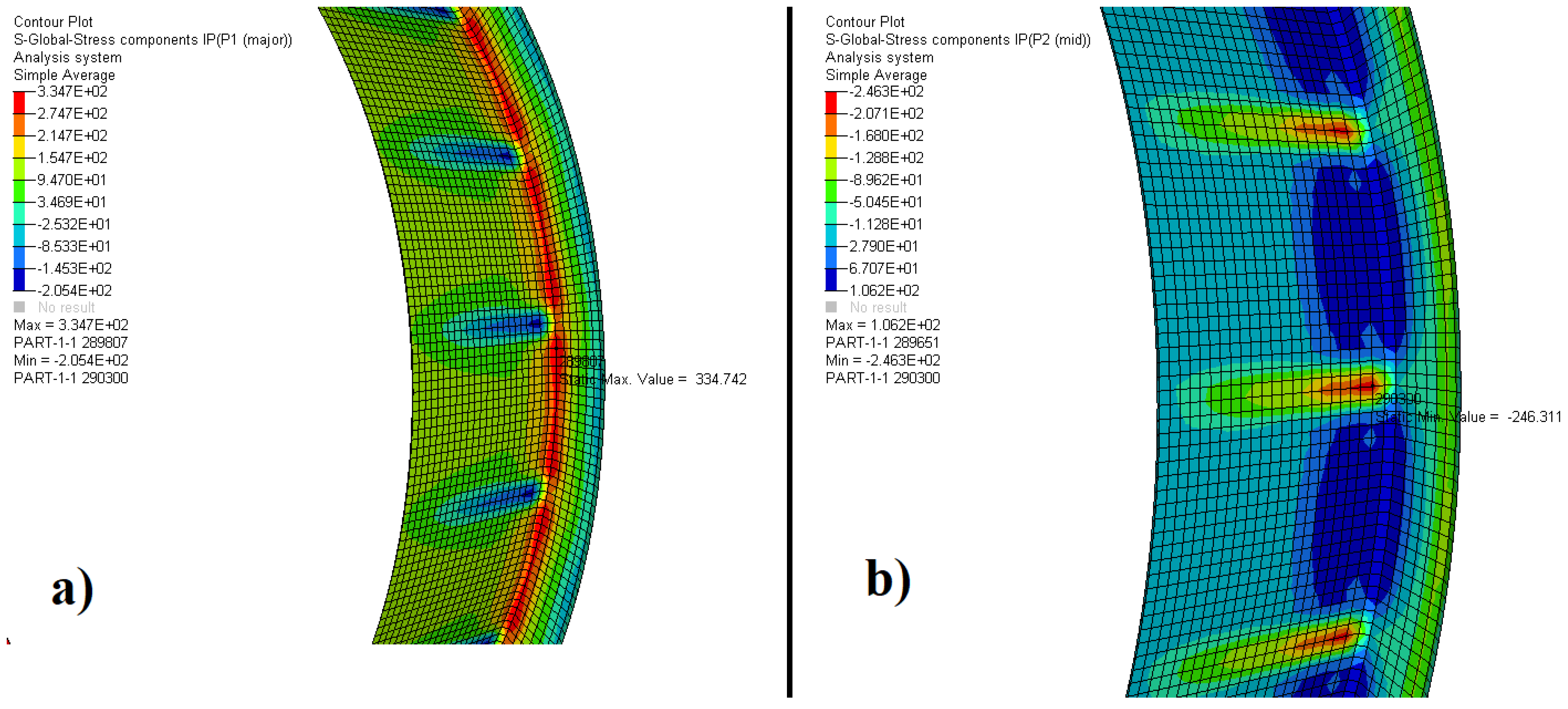
- The results of photoelasticity are in agreement with those obtained by finite elements since the tensions were concentrated in the same regions;
- (b)
- The difference of the principal stresses of the finite element analysis was obtained from the maximum points for each stress (which are not necessarily coincident) in a three-dimensional model. For the photoelastic analyses, this difference of the principal stresses was obtained for the same point and in two-dimensional figures. This may have influenced the percentage difference between the numerical and experimental results presented in Table 5;
- (c)
- During the heating of the resin model in the stress freezing method, the Poisson’s coefficient may have increased and influenced the difference between the results;
- (d)
- The SLA-Clear epoxy resin was suitable for photoelastic analysis and the stress freezing method because the resin is transparent and provides good optical response generating well-defined isochromatic fringes. In addition to retaining the stress distribution after the thermal process;
- (e)
- The cage had no photoelastic fringe, so it is assumed that the function of the cage is to keep the rolling elements equally spaced;
- (f)
- Considering the difference between experimental and numerical results, it can be concluded that photoelasticity can assist during design when numerical results are far from the correct result. Checking the results using the technique described in this paper before constructing a prototype can be more economical and safer than a design error prototype;
- (g)
- The printing of photoelastic models by the stereolithographic process is very useful and makes experimental analysis much easier since the time spent producing the models can be used to perform more constructive research tasks;
- (h)
- The possibility of making complex models by the stereolithographic process may increase interest in photoelastic technique and create interest in developing more suitable materials for photoelastic analysis.
5. Conclusions
Author Contributions
Funding
Acknowledgments
Conflicts of Interest
References
- Ramesh, K.; Pandey, A. An improved normalization technique for white light photoelasticity. Opt. Lasers Eng. 2018, 109, 7–16. [Google Scholar] [CrossRef]
- Kale, S.; Ramesh, K. Advancing front scanning approach for three-fringe photoelasticity. Opt. Lasers Eng. 2013, 51, 592–599. [Google Scholar] [CrossRef]
- Ramesh, K.; Hariprasad, M.P.; Bhuvanewari, S. Digital photoelastic analysis applied to implant dentistry. Opt. Lasers Eng. 2016, 87, 204–213. [Google Scholar] [CrossRef]
- Simon, B.N.; Kasimayan, T.; Ramesh, K. The influence of ambient illumination on colour adaptation in three fringe photoelasticity. Opt. Lasers Eng. 2011, 49, 258–264. [Google Scholar] [CrossRef]
- Patil, P.; Vyasarayani, C.P.; Ramji, M. Linear least squares approach for evaluating crack tip fracture parameters using isochromatic and isoclinic data from digital photoelasticity. Opt. Lasers Eng. 2017, 93, 182–194. [Google Scholar] [CrossRef]
- Ramakrishnan, V.; Ramesh, K. Scanning schemes in white light Photoelasticity–Part I: Critical assessment of existing schemes. Opt. Lasers Eng. 2017, 92, 129–140. [Google Scholar] [CrossRef]
- Ju, Y.; Wang, L.; Xie, H.; Ma, G.; Zheng, Z.; Mao, L. Visualization and Transparentization of the Structure and Stress Field of Aggregated Geomaterials Through 3D Printing and Photoelastic Techniques. Rock Mech. Rock Eng. 2017, 50, 1383–1407. [Google Scholar] [CrossRef]
- Quiroga, J.A.; Gómez-Pedrero, J.A. Application of principal component analysis in phase-shifting photoelasticity. Opt. Express 2016, 24, 5984. [Google Scholar] [CrossRef]
- Júnior, P.A.A.M.; Rios, I.G.; Vieira, F.G.; Ribeiro, J.S.; Magalhães, C.A. Numerical method to digital photoelasticity using plane polariscope. Opt. Express 2016, 24, 12617. [Google Scholar] [CrossRef]
- Forte, P.; Paoli, A.; Razionale, A.V. A CAE approach for the stress analysis of gear models by 3D digital photoelasticity. Int. J. Interact. Des. Manuf. 2015, 9, 31–43. [Google Scholar] [CrossRef]
- Ajovalasit, A.; Petrucci, G.; Scafidi, M. Review of RGB photoelasticity. Opt. Lasers Eng. 2015, 68, 58–73. [Google Scholar] [CrossRef]
- Ramakrishnan, V.; Ramesh, K. Scanning schemes in white light photoelasticity–Part II: Novel fringe resolution guided scanning scheme. Opt. Lasers Eng. 2017, 92, 141–149. [Google Scholar] [CrossRef]
- Ju, Y.; Ren, Z.; Wang, L.; Mao, L.; Chiang, F.-P. Photoelastic method to quantitatively visualise the evolution of whole-field stress in 3D printed models subject to continuous loading processes. Opt. Lasers Eng. 2018, 100, 248–258. [Google Scholar] [CrossRef]
- Swain, D.; Philip, J.; Pillai, S.A. A modified regularized scheme for isochromatic demodulation in RGB photoelasticity. Opt. Lasers Eng. 2014, 61, 39–51. [Google Scholar] [CrossRef]
- Swain, D.; Thomas, B.P.; Philip, J.; Pillai, S.A. Novel calibration and color adaptation schemes in three-fringe RGB photoelasticity. Opt. Lasers Eng. 2015, 66, 320–329. [Google Scholar] [CrossRef]
- Yang, Q.; Zhu, W.; Lu, Z.; Li, D.; Wang, Z.; Wang, F. Rapid fabrication of high-performance CaO-based integral ceramic mould by stereolithography and non-aqueous gelcasting. Materials 2019, 12, 934. [Google Scholar] [CrossRef]
- Linares-Alvelais, J.A.R.; Obedt Figueroa-Cavazos, J.; Chuck-Hernandez, C.; Siller, H.R.; Rodríguez, C.A.; Martínez-López, J.I. Hydrostatic high-pressure post-processing of specimens fabricated by DLP, SLA, and FDM: An alternative for the sterilization of polymer-based biomedical devices. Materials 2018, 11, 2540. [Google Scholar] [CrossRef]
- Komissarenko, D.A.; Sokolov, P.S.; Evstigneeva, A.D.; Shmeleva, I.A.; Dosovitsky, A.E. Rheological and curing behavior of acrylate-based suspensions for the DLP 3D printing of complex zirconia parts. Materials 2018, 11, 2350. [Google Scholar] [CrossRef]
- Kačarević, Ž.P.; Rider, P.M.; Alkildani, S.; Retnasingh, S.; Smeets, R.; Jung, O.; Ivanišević, Z.; Barbeck, M. An introduction to 3D bioprinting: Possibilities, challenges and future aspects. Materials 2018, 11, 2199. [Google Scholar] [CrossRef]
- Chung, Y.J.; Park, J.M.; Kim, T.H.; Ahn, J.S.; Cha, H.S.; Lee, J.H. 3D printing of resin material for denture artificial teeth: Chipping and indirect tensile fracture resistance. Materials 2018, 11, 1798. [Google Scholar] [CrossRef]
- Arnold, C.; Monsees, D.; Hey, J.; Schweyen, R. Surface quality of 3D-printed models as a function of various printing parameters. Materials 2019, 12, 1970. [Google Scholar] [CrossRef] [PubMed]
- Fernández, M.S.-B. Metrological considerations in the measurement of contact stress parameters using photoelasticity. Opt. Lasers Eng. 2019, 117, 29–39. [Google Scholar] [CrossRef]
- Karalekas, D.E.; Agelopoulos, A. On the use of stereolithography built photoelastic models for stress analysis investigations. Mater. Des. 2006, 27, 100–106. [Google Scholar] [CrossRef]
- Madhu, K.R.; Ramesh, K. Noise removal in three-fringe photoelasticity by adaptive colour difference estimation. Opt. Lasers Eng. 2007, 45, 175–182. [Google Scholar] [CrossRef]
- Dubey, V.N.; Grewal, G.S. Noise removal in three-fringe photoelasticity by median filtering. Opt. Lasers Eng. 2009, 47, 1226–1230. [Google Scholar] [CrossRef]
- Zhang, Y.-T.; Huang, M.-J.; Liang, H.-R.; Lao, F.-Y. Branch cutting algorithm for unwrapping photoelastic phase map with isotropic point. Opt. Lasers Eng. 2012, 50, 619–631. [Google Scholar] [CrossRef]


| Property | |
|---|---|
| Hardness (Shore) | 86 D |
| Specific mass | 1.21 g/cm3 |
| Stretching | 5–13% (at break) |
| Deflection temperature at 0.4551 MPa | 53–55 °C |
| Deflection temperature at 1.8202 MPa | 48–50 °C |
| Tensile strength | 58–68 MPa |
| Modulus of elasticity | 2.69–3.10 GPa |
| Bending strength | 87–101 MPa |
| Modulus of flexion | 2.70–3.00 MPa |
| Glass transition temperature | 58 °C |
| Description | Value | Unit |
|---|---|---|
| Initial contact angle | 11.60 | ° |
| Final contact angle | 14.67 | ° |
| Flange angle | 76.87 | ° |
| Angle of conical roller | 3.07 | ° |
| Length of conical roller | 14.63 | mm |
| Smallest diameter of conical roller | 6.73 | mm |
| Largest conical roller diameter | 7.48 | mm |
| Width of outer ring | 15.50 | mm |
| Width of inner ring | 20.00 | mm |
| Bearing outer diameter | 75.00 | mm |
| Bearing inner diameter | 45.00 | mm |
| Initial diameter-inner race | 50.34 | mm |
| Final diameter-outer race | 71.16 | mm |
| Effective bearing center | 16.00 | mm |
| Difference of the Principal Stresses | Cone Roller | Outer Ring | Inner Ring |
|---|---|---|---|
| (σ1–σ2) [MPa] | 4.03 | 3.34 | 4.00 |
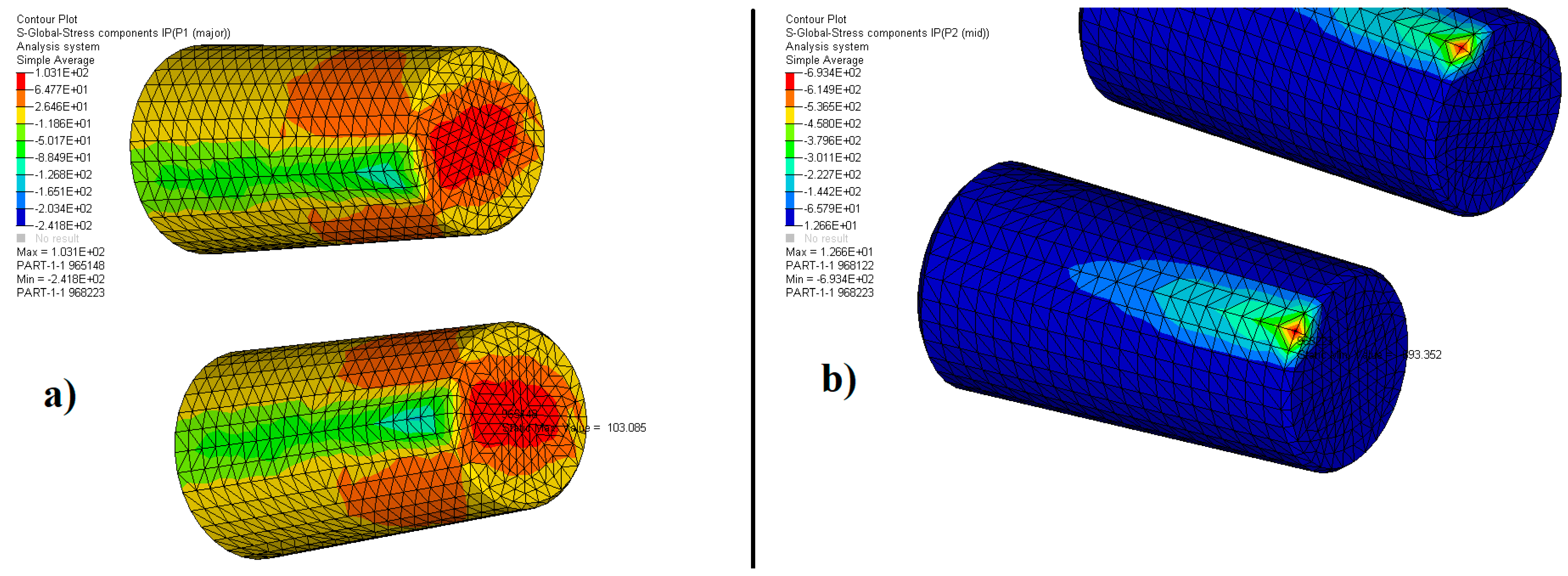
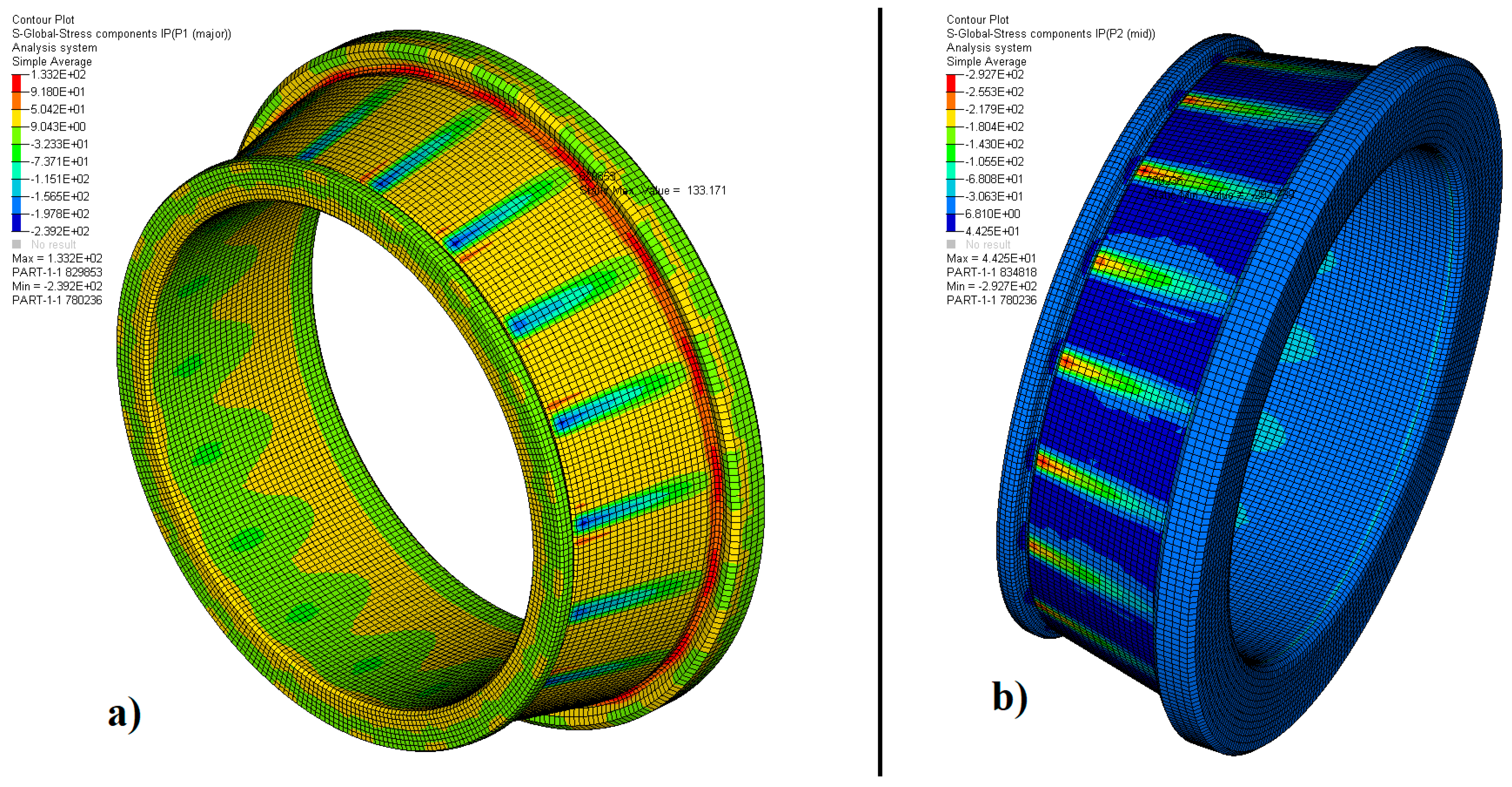
| Principal Stresses | Cone Roller | Outer Ring | Inner Ring |
|---|---|---|---|
| σ1 [MPa] | 103.1 | 334.7 | 133.2 |
| σ2 [MPa] | −693.4 | −246.3 | −292.7 |
| (σ1–σ2) [MPa] | 796.5 | 581.0 | 425.9 |
| Difference of the Principal Stresses | Cone Roller | Outer Ring | Inner Ring |
|---|---|---|---|
| σp = (σ1–σ2) [MPa] | 796.5 | 581.0 | 425.9 |
| σm = (σ1–σ2) [MPa] | 4.03 | 3.34 | 4.00 |
| σ = σp/σm | 197.6 | 174.0 | 105.7 |
| F = Fp/Fm | 160 | 160 | 160 |
| E = |σ−F|/F | 23.5% | 8.8% | 33.9% |
© 2019 by the authors. Licensee MDPI, Basel, Switzerland. This article is an open access article distributed under the terms and conditions of the Creative Commons Attribution (CC BY) license (http://creativecommons.org/licenses/by/4.0/).
Share and Cite
Vieira, F.G.; Scari, A.S.; Magalhães Júnior, P.A.A.; Martins, J.S.R.; Magalhães, C.A. Analysis of Stresses in a Tapered Roller Bearing Using Three-Dimensional Photoelasticity and Stereolithography. Materials 2019, 12, 3427. https://doi.org/10.3390/ma12203427
Vieira FG, Scari AS, Magalhães Júnior PAA, Martins JSR, Magalhães CA. Analysis of Stresses in a Tapered Roller Bearing Using Three-Dimensional Photoelasticity and Stereolithography. Materials. 2019; 12(20):3427. https://doi.org/10.3390/ma12203427
Chicago/Turabian StyleVieira, Filipe Gomes, Alexandre S. Scari, Pedro Américo Almeida Magalhães Júnior, Jordana S. R. Martins, and Cristina Almeida Magalhães. 2019. "Analysis of Stresses in a Tapered Roller Bearing Using Three-Dimensional Photoelasticity and Stereolithography" Materials 12, no. 20: 3427. https://doi.org/10.3390/ma12203427
APA StyleVieira, F. G., Scari, A. S., Magalhães Júnior, P. A. A., Martins, J. S. R., & Magalhães, C. A. (2019). Analysis of Stresses in a Tapered Roller Bearing Using Three-Dimensional Photoelasticity and Stereolithography. Materials, 12(20), 3427. https://doi.org/10.3390/ma12203427