The Effect of the Static Load in the UNSM Process on the Corrosion Properties of Alloy 600


Abstract
1. Introduction
2. Materials and Methods
2.1. Specimen
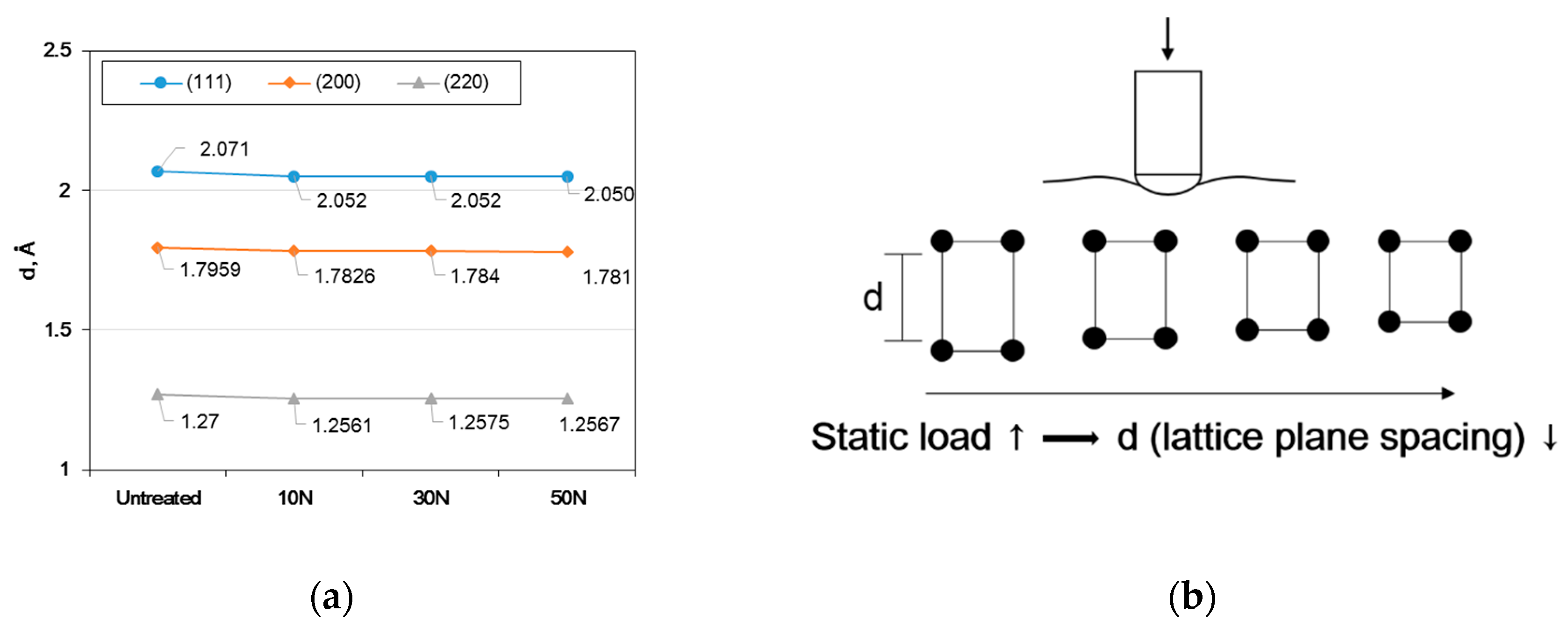
2.2. Microstructure Analysis
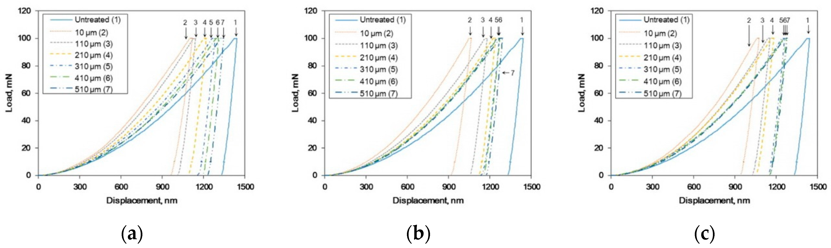
2.3. Hardness and Residual Stress Measurements
2.4. Electrochemical Tests
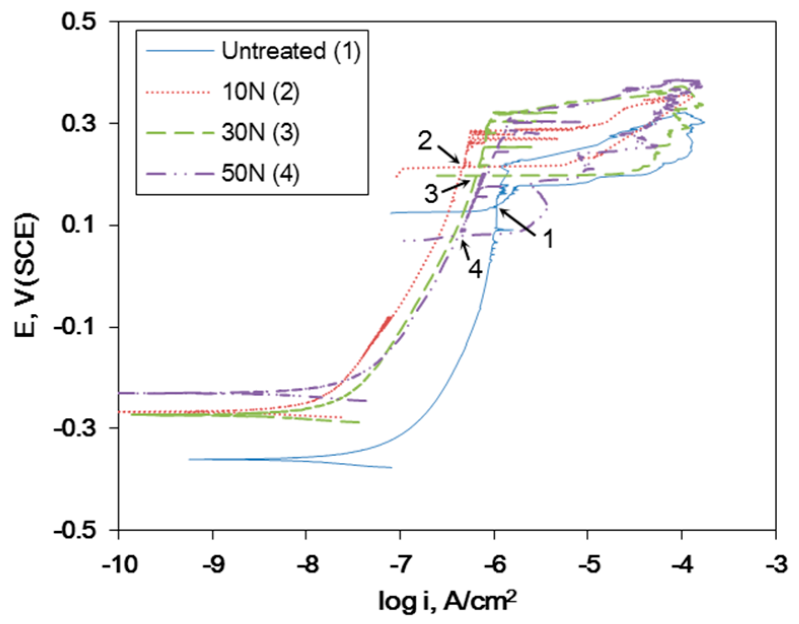
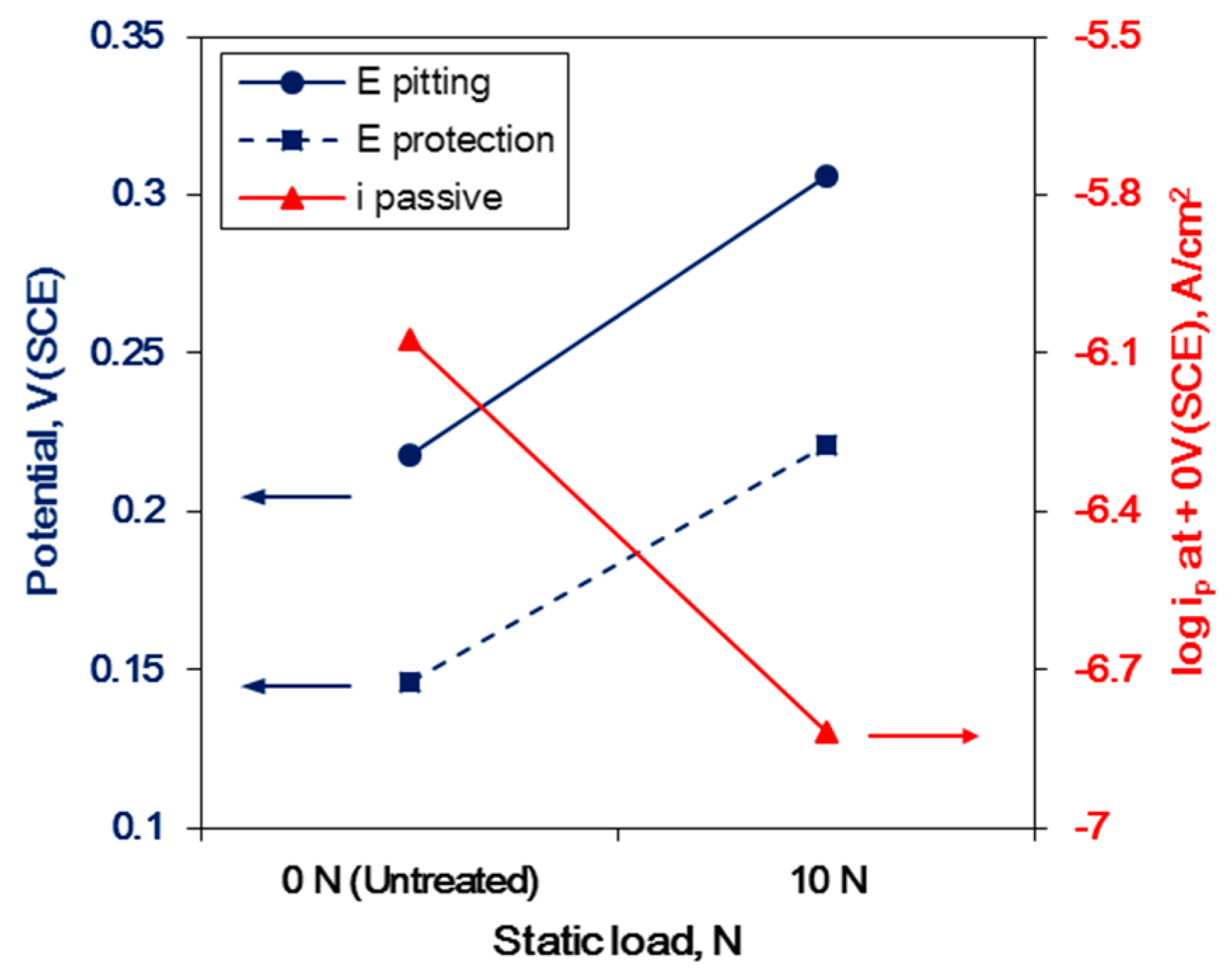
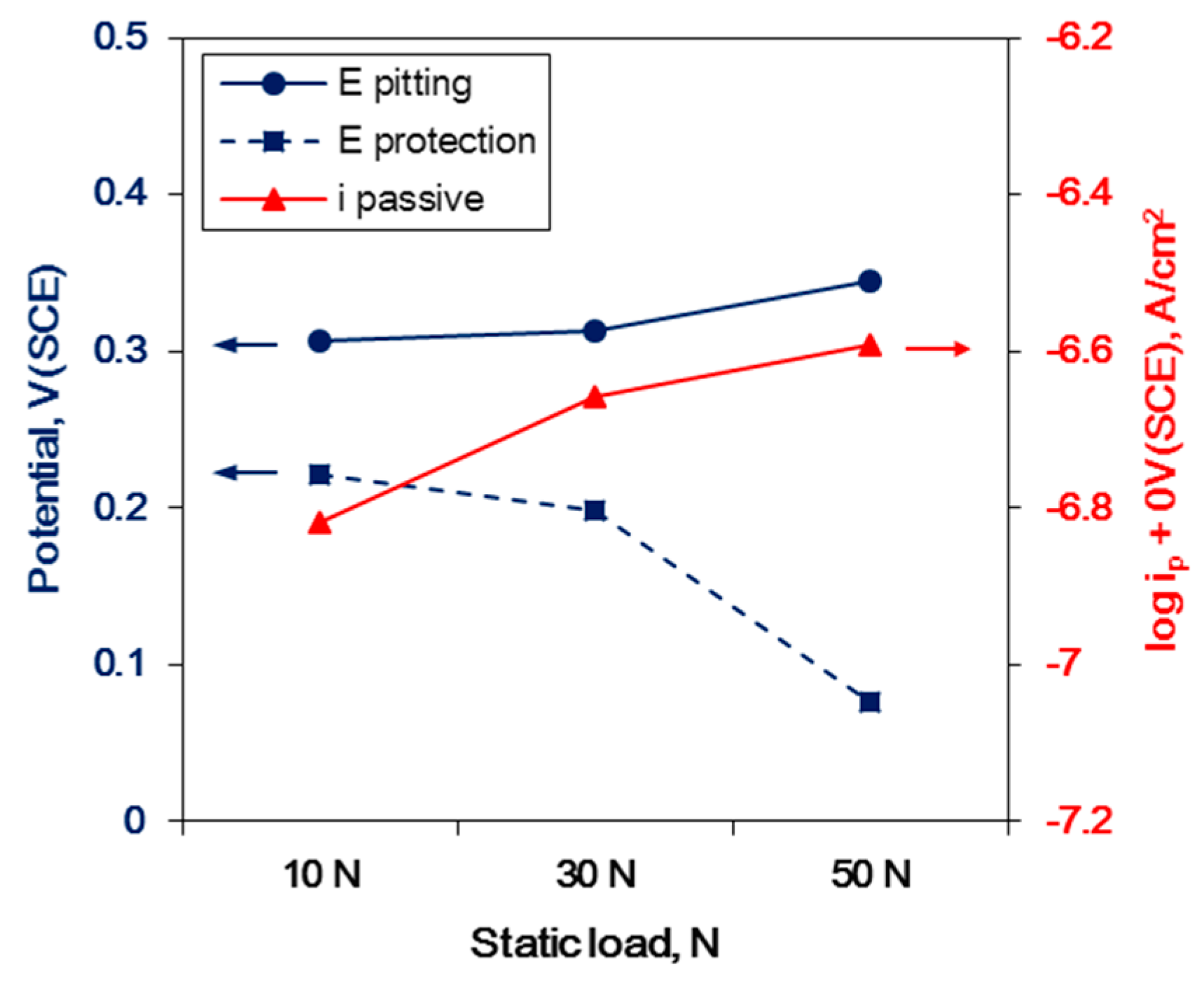
2.4.1. Cyclic Polarization Test
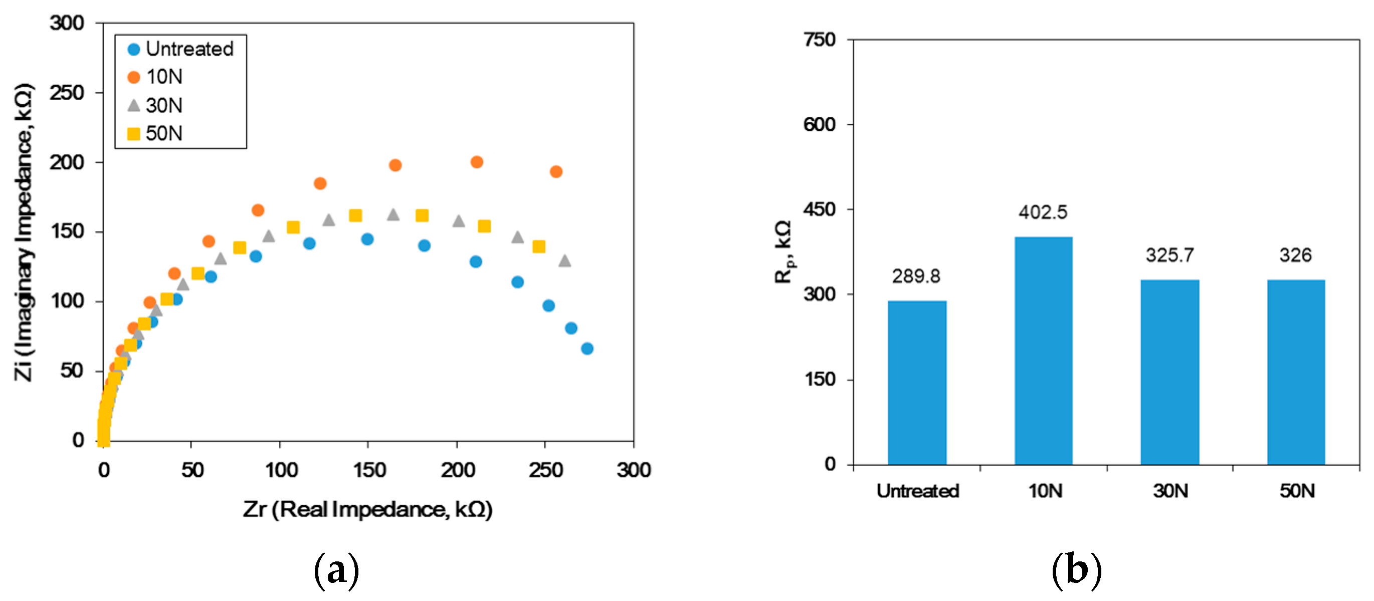
2.4.2. AC-Impedance Measurement
3. Results
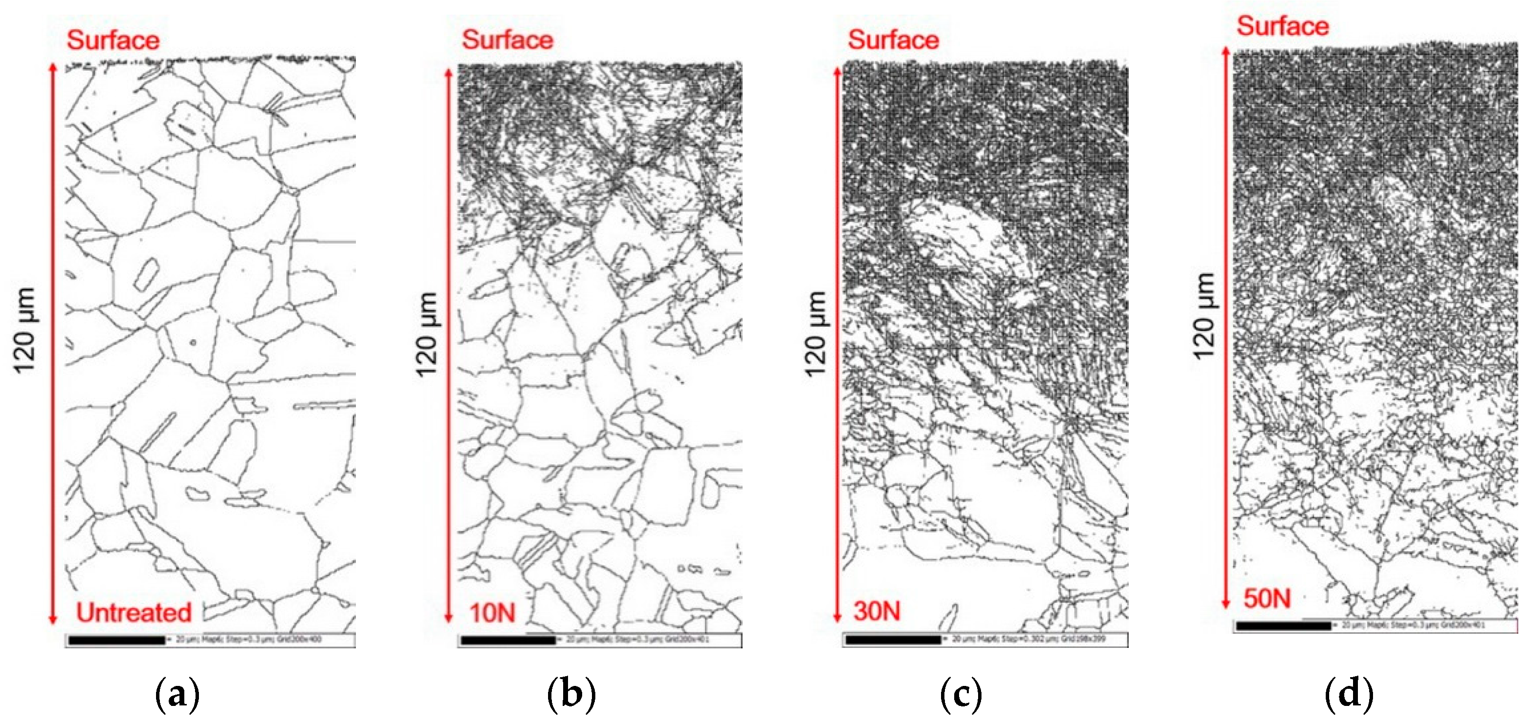
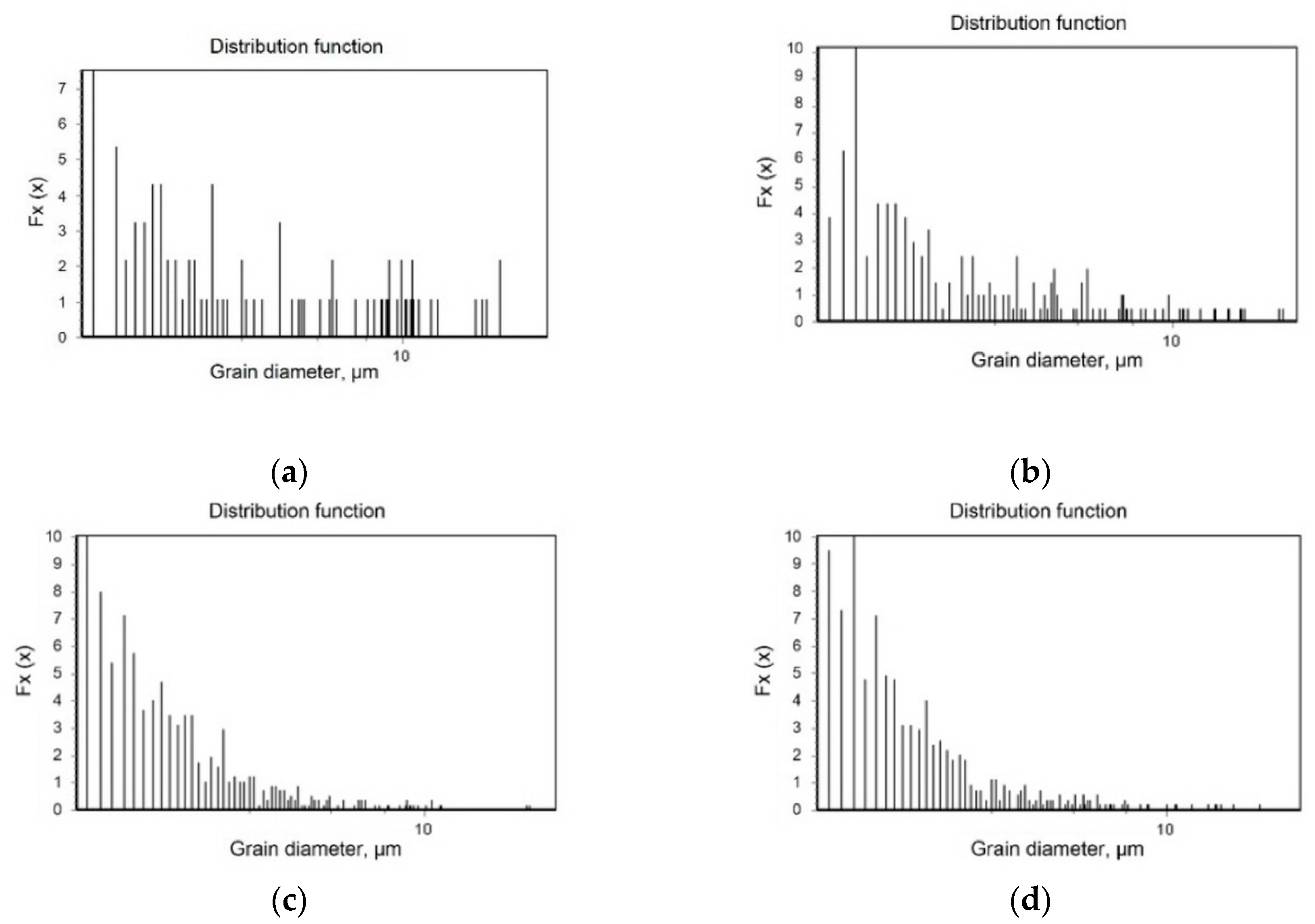
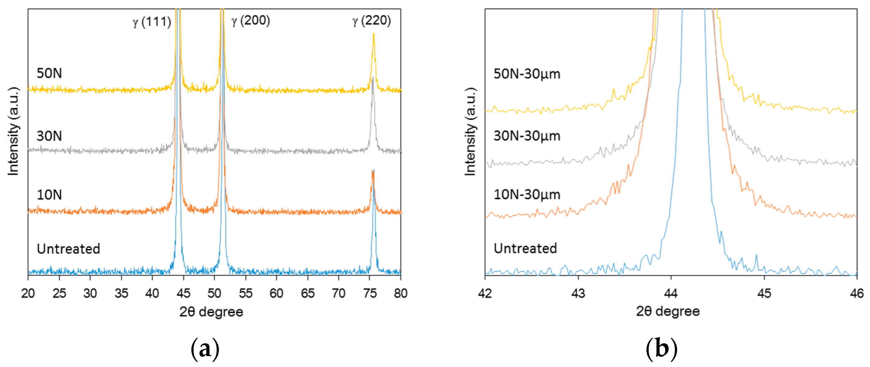
3.1. The Effect of the Static Load in UNSM Treatment on the Microstructure of Alloy 600
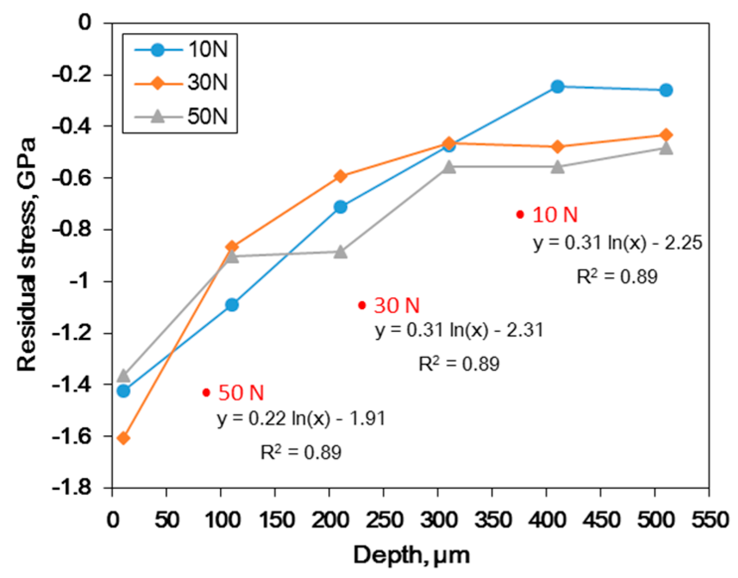
3.2. The Effect of the Static Load in UNSM Treatment on the Residual Stress of Alloy 600.
3.3. The Effect of the Static Load in UNSM Treatment on Corrosion Properties
4. Discussion
5. Conclusions
Author Contributions
Funding
Acknowledgments
Conflicts of Interest
References
- Smith, W.F. Structure and Properties of Engineering Alloys, 2nd ed.; McGraw-Hill: New York, NY, USA, 1993; p. 494. [Google Scholar]
- Crooker, P.; Lian, T. Materials Reliability Program: Technical Basis for Primary Water Stress Corrosion Cracking Mitigation by Surface Stress Improvement, MRP-267, Revision 2, EPRI, 2016 Technical Report. Available online: https://www.epri.com/#/pages/product/000000003002008083/?lang=en-US (accessed on 22 September 2019).
- Crooker, P. Materials Reliability Program: Topical Report for Primary Water Stress Corrosion Cracking Mitigation by Surface Stress Improvement (MRP-335, Revision 3-A), EPRI, 2016 Technical Report. Available online: https://www.epri.com/#/pages/product/3002007392/?lang=en-US (accessed on 22 September 2019).
- Arioka, K.; Yamada, T.; Miyamoto, T.; Aoki, M. Intergranular Stress Corrosion Cracking Growth Behavior of Ni-Cr-Fe Alloys in Pressurized Water Reactor Primary Water. Corros. 2014, 70, 695–707. [Google Scholar] [CrossRef]
- Bruemmer, S.M.; Thomas, L.E. High-resolution analytical electron microscopy characterization of corrosion and cracking at buried interfaces. Surf. Interface Anal. 2001, 31, 571–581. [Google Scholar] [CrossRef]
- Shen, Z.; Arioka, K.; Lozano-Perez, S. A mechanistic study of SCC in Alloy 600 through high-resolution characterization. Corros. Sci. 2018, 132, 244–259. [Google Scholar] [CrossRef]
- Lim, Y.S.; Kim, H.P.; Hwang, S.S. Microstructural characterization on intergranular stress corrosion cracking of Alloy 600 in PWR primary water environment. J. Nucl. Mater. 2013, 440, 46–54. [Google Scholar] [CrossRef]
- Feron, D.; Staehle, R.W. Stress Corrosion Cracking of Nickel-Based Alloys in Water-Cooled Nuclear Reactors: The Coriou Effect; Elsevier: Cambridge, MA, USA, 2016; pp. 20–39. [Google Scholar]
- Tsai, W.-T.; Chang, C.-S.; Lee, J.-T. Effects of Shot Peening on Corrosion and Stress Corrosion Cracking Behaviors of Sensitized Alloy 600 in Thiosulfate Solution. Corros. Sci. 1994, 50, 98–105. [Google Scholar] [CrossRef]
- Friske, W.H.; Page, J.P. Shot peening to prevent the corrosion cracking of austenitic stainless steels. J. Mater. Energy Syst. 1979, 1, 20–32. [Google Scholar] [CrossRef]
- Badran, O.; Kloub, N.; Tal, M.A. The Effect of Shot Peening and Polishing on the Pitting Corrosion Resistance of Stainless Steel. Am. J. Appl. Sci. 2008, 5, 1397–1402. [Google Scholar] [CrossRef]
- Telang, A.; Gill, A.S.; Teysseyre, S.; Mannava, S.R.; Qian, D.; Vasudevan, V.K. Effects of laser shock peening on SCC behavior of Alloy 600 in tetrathionate solution. Corros. Sci. 2015, 90, 434–444. [Google Scholar] [CrossRef]
- Lu, J.; Qi, H.; Luo, K.; Luo, M.; Cheng, X. Corrosion behaviour of AISI 304 stainless steel subjected to massive laser shock peening impacts with different pulse energies. Corros. Sci. 2014, 80, 53–59. [Google Scholar] [CrossRef]
- Karthik, D.; Swaroop, S. Laser shock peening enhanced corrosion properties in a nickel based Inconel 600 superalloy. J. Alloy. Compd. 2017, 694, 1309–1319. [Google Scholar] [CrossRef]
- Peyre, P.; Scherpereel, X.; Berthe, L.; Carboni, C.; Fabbro, R.; Beranger, G.; Lemaître, C. Surface modifications induced in 316L steel by laser peening and shot-peening. Influence on pitting corrosion resistance. Mater. Sci. Eng. A 2000, 280, 294–302. [Google Scholar] [CrossRef]
- Lu, J.; Luo, K.; Yang, D.; Cheng, X.; Hu, J.; Dai, F.; Qi, H.; Zhang, L.; Zhong, J.; Wang, Q.; et al. Effects of laser peening on stress corrosion cracking (SCC) of ANSI 304 austenitic stainless steel. Corros. Sci. 2012, 60, 145–152. [Google Scholar] [CrossRef]
- Hirano, K.; Enomoto, K.; Hayashi, E.; Kurosawa, K. Effects of water jet peening on corrosion resistance and fatigue strength of type 304 stainless steel. J. Soc. Mater. Sci. Japan 1996, 45, 740–745. [Google Scholar] [CrossRef]
- Ijiri, M.; Shimonishi, D.; Tani, S.; Okada, N.; Yamamoto, M.; Nakagawa, D.; Tanaka, K.; Yoshimura, T. Improvement of corrosion resistance of magnesium alloy by high temperature high-pressure cavitation treatment. Inter. J. Lightweight Mater. Manufacture 2019, 2, 255–260. [Google Scholar] [CrossRef]
- Feng, Y.; Hu, S.; Wang, D.; Liu, J.; Zhang, C. Effects of ultrasonic peening treatment on hydrogen sulphide corrosion behavior. Surf. Eng. 2017, 33, 696–705. [Google Scholar] [CrossRef]
- Ahmad, B.; Fitzpatrick, M.E. Effect of ultrasonic peening and accelerated corrosion exposure on the residual stress distribution in welded marine steel. Metal. Mater. Trans. A 2015, 46, 1214–1226. [Google Scholar] [CrossRef]
- Khan, M.; Fitzpatrick, M.; Wang, Q.; Pyoun, Y.; Amanov, A. Effect of ultrasonic nanocrystal surface modification on residual stress and fatigue cracking in engineering alloys. Fatigue Fract. Eng. Mater. Struct. 2017, 41, 844–855. [Google Scholar] [CrossRef]
- Ye, C.; Telang, A.; Gill, A.S.; Suslov, S.; Idell, Y.; Zweiacker, K.; Wiezorek, J.M.; Zhou, Z.; Qian, D.; Mannava, S.R.; et al. Gradient nanostructure and residual stresses induced by Ultrasonic Nano-crystal Surface Modification in 304 austenitic stainless steel for high strength and high ductility. Mater. Sci. Eng. A 2014, 613, 274–288. [Google Scholar] [CrossRef]
- Cherif, A.; Pyoun, Y.; Scholtes, B. Effects of ultrasonic nanocrystal surface modification (UNSM) on residual stress state and fatigue strength of AISI 304. J. Mater. Eng. Perform. 2010, 19, 282–286. [Google Scholar] [CrossRef]
- Khan, M.K.; Liu, Y.J.; Wang, Q.Y.; Pyun, Y.S.; Kayumov, R. Effect of ultrasonic nanocrystal surface modification on the characteristics of AISI 310 stainless steel up to very high cycle fatigue. Fatigue Fract. Eng. Mater. Struct. 2016, 39, 427–438. [Google Scholar] [CrossRef]
- Amanova, A.; Karimbaeva, R.; Malekib, E.; Unalc, O.; Pyuna, Y.S.; Amanovd, T. Effect of combined shot peening and ultrasonic nanocrystal surface modification processes on the fatigue performance of AISI 304. Sur. Coat. Tech. 2019, 358, 695–705. [Google Scholar] [CrossRef]
- Amanov, A.; Umarov, R. The effects of ultrasonic nanocrystal surface modification temperature on the mechanical properties and fretting wear resistance of Inconel 690 alloy. Appl. Surf. Sci. 2018, 441, 515–529. [Google Scholar] [CrossRef]
- Lee, J.; Kim, K.; Pyoun, Y.; Kim, Y. Intergranular Corrosion Mechanism of Slightly-sensitized and UNSM-treated 316L Stainless Steel. Corros. Sci. Technol. 2016, 15, 226–236. [Google Scholar] [CrossRef]
- Lee, J.; Kim, Y. Intergranular Corrosion of 316L Stainless Steel by Aging and UNSM (Ultrasonic Nano-crystal Surface Modification) treatment. Corros. Sci. Technol. 2015, 14, 313–324. [Google Scholar] [CrossRef]
- Kim, K.-T.; Lee, J.-H.; Kim, Y.-S. Effect of Ultrasonic Nano-Crystal Surface Modification (UNSM) on the Passivation Behavior of Aged 316L Stainless Steel. Materials. 2017, 10, 713. [Google Scholar] [CrossRef]
- Li, S.; Ren, Z.; Dong, Y.; Ye, C.; Cheng, G.; Cong, H. Enhanced Pitting Corrosion Resistance of 304 SS in 3.5 wt% NaCl by Ultrasonic Nanocrystal Surface Modification. J. Electrochem. Soc. 2017, 164, C682–C689. [Google Scholar] [CrossRef]
- Ye, C.; Telang, A.; Gill, A.; Wen, X.; Mannava, S.R.; Qian, D.; Vasudevan, V.K. Effects of Ultrasonic Nanocrystal Surface Modification on the Residual Stress, Microstructure, and Corrosion Resistance of 304 Stainless Steel Welds. Met. Mater. Trans. A 2018, 49, 972–978. [Google Scholar] [CrossRef]
- He, Y.; Li, K.; Cho, I.S.; Lee, C.S.; Park, I.G.; Song, J.-I.; Yang, C.-W.; Lee, J.-H.; Shin, K. Microstructural Characterization of SS304 upon Various Shot Peening Treatments. Appl. Microsc. 2015, 45, 155–169. [Google Scholar] [CrossRef]
- Wang, K.; Tao, N.; Liu, G.; Lu, J.; Lu, K. Plastic strain-induced grain refinement at the nanometer scale in copper. Acta Mater. 2006, 54, 5281–5291. [Google Scholar] [CrossRef]
- Umemoto, M.; Todaka, Y.; Tsuchiya, K. Formation of Nanocrystalline Structure in Steels by Air Blast Shot Peening. Mater. Trans. 2003, 44, 1488–1493. [Google Scholar] [CrossRef]
- Luo, S.; Zhou, L.; Wang, X.; Cao, X.; Nie, X.; He, W. Surface Nanocrystallization and Amorphization of Dual-Phase TC11 Titanium Alloys under Laser Induced Ultrahigh Strain-Rate Plastic Deformation. Materials. 2018, 11, 563. [Google Scholar] [CrossRef]
- Jang, J.I. Estimation of residual stress by instrumented indentation: A review. J. Ceramic Proc. Research 2009, 10, 391–400. [Google Scholar]
- Dean, J.; Aldrich-Smith, G.; Clyne, T. Use of nanoindentation to measure residual stresses in surface layers. Acta Mater. 2011, 59, 2749–2761. [Google Scholar] [CrossRef]
- Lee, Y.H.; Choi, Y.; Kwon, D. Evaluation of thin film residual stress through the nanoindentation technique and the modeling of stress relaxation. J. Kor. Inst. Met. Mater. 2001, 39, 1101–1107. [Google Scholar]
- Wu, Q.; Xie, D.; Jia, Z.; Zhang, Y.; Zhang, H. Effect of shot peening on surface residual stress distribution of SiCp/2024Al. Composites Part B 2018, 154, 382–387. [Google Scholar] [CrossRef]
- Kobayashi, M.; Matsui, T.; Murakami, Y. Mechanism of creation of compressive residual stress by shot peening. Int. J. Fatigue 1998, 20, 351–357. [Google Scholar] [CrossRef]
- Askeland, D.R.; Wright, W.J. The Science and Engineering of Materials, 6th ed.; Cengage Learning: Stamford, CT, USA, 2010; pp. 304–305. [Google Scholar]
- Ralston, K.D.; Birbilis, N. Effect of grain size on corrosion: A review, corrosion. Corrosion 2010, 66, 075005-075005-13. [Google Scholar] [CrossRef]
- Balakrishnan, A.; Lee, B.C.; Kim, T.N.; Panigrahi, B.B. Corrosion behaviour of ultra fine grained titanium in simulated body fluid for implant application. Trends Biomater. Artif. Organs 2008, 22, 58–64. [Google Scholar]
- Balyanov, A. Corrosion resistance of ultra fine-grained Ti. Scr. Mater. 2004, 51, 225–229. [Google Scholar] [CrossRef]
- Wang, X.; Li, D. Mechanical and electrochemical behavior of nanocrystalline surface of 304 stainless steel. Electrochimica Acta 2002, 47, 3939–3947. [Google Scholar] [CrossRef]
- Zeiger, W.; Schneider, M.; Scharnweber, D.; Worch, H. Corrosion behaviour of a nanocrystalline FeA18 alloy. Nanostructured Mater. 1995, 6, 1013–1016. [Google Scholar] [CrossRef]
- Fontana, M.G. Corrosion Engineering, 3rd ed.; Mc-Graw-Hill Book Co.: New York, NY, USA, 1987; pp. 29–31. [Google Scholar]
- Splinter, S.J.; Rofagha, R.; McIntyre, N.S.; Erb, U. XPS Characterization of the Corrosion Films Formed on Nanocrystalline Ni–P Alloys in Sulphuric Acid. Surf. Interface Anal. 1996, 24, 181–186. [Google Scholar] [CrossRef]
- Wang, X.; Li, D. Mechanical, electrochemical and tribological properties of nano-crystalline surface of 304 stainless steel. Wear 2003, 255, 836–845. [Google Scholar] [CrossRef]
- Wang, T.; Yu, J.; Dong, B. Surface nanocrystallization induced by shot peening and its effect on corrosion resistance of 1Cr18Ni9Ti stainless steel. Surf. Coatings Technol. 2006, 200, 4777–4781. [Google Scholar] [CrossRef]
- Liu, K.T.; Duh, J.G. Grain size effects on the corrosion behavior of Ni50.5Ti49.5 and Ni45.6Ti49.3Al5.1 films. J. Electroanal. Chem. 2008, 618, 45–52. [Google Scholar] [CrossRef]
- Ghosh, S.; Dey, G.; Dusane, R.; Grover, A. Improved pitting corrosion behaviour of electrodeposited nanocrystalline Ni–Cu alloys in 3.0wt.% NaCl solution. J. Alloy. Compd. 2006, 426, 235–243. [Google Scholar] [CrossRef]
- Takakuwa, O.; Soyama, H. Effect of Residual Stress on the Corrosion Behavior of Austenitic Stainless Steel. Adv. Chem. Eng. Sci. 2015, 5, 62–71. [Google Scholar] [CrossRef]
- Wu, B.; Zhang, J.; Zhang, L.; Pyoun, Y.-S.; Murakami, R.-I. Effect of ultrasonic nanocrystal surface modification on surface and fatigue properties of quenching and tempering S45C steel. Appl. Surf. Sci. 2014, 321, 318–330. [Google Scholar] [CrossRef]


| Ni | Cr | Fe | C | Mn | S | Si | Cu |
|---|---|---|---|---|---|---|---|
| 73.13 | 16.35 | 9.42 | 0.07 | 0.21 | 0.002 | 0.29 | 0.01 |
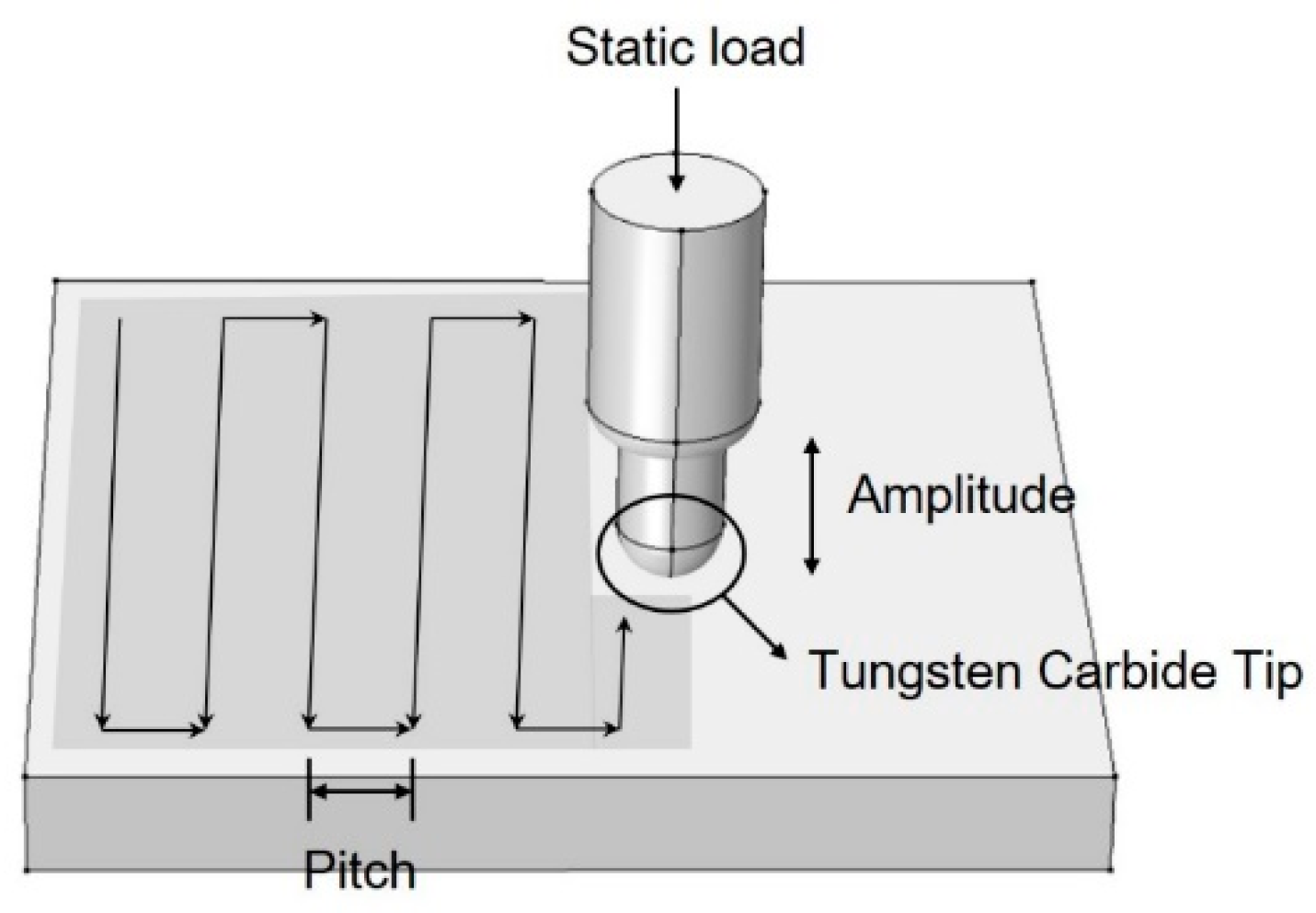
| Sample Name | Static Load (N) | Amplitude (μm) | Pitch (mm) | Tip Diameter(mm) |
|---|---|---|---|---|
| Untreated | - | - | - | - |
| 10 N | 10 | 30 | 0.07 | 2.38 (WC1) |
| 30 N | 30 | 30 | 0.07 | 2.38 (WC) |
| 50 N | 50 | 30 | 0.07 | 2.38 (WC) |
| Static Load | Untreated | 10 N | 30 N | 50 N |
|---|---|---|---|---|
| Epitting, V(SCE) | 0.218 | 0.306 | 0.313 | 0.345 |
| Eprotection, V(SCE) | 0.146 | 0.221 | 0.198 | 0.079 |
| ipassive, A/cm2 at 0 V(SCE) | 10-6.074 | 10-6.819 | 10-6.658 | 10-6.593 |
© 2019 by the authors. Licensee MDPI, Basel, Switzerland. This article is an open access article distributed under the terms and conditions of the Creative Commons Attribution (CC BY) license (http://creativecommons.org/licenses/by/4.0/).
Share and Cite
Kim, K.T.; Kim, Y.S. The Effect of the Static Load in the UNSM Process on the Corrosion Properties of Alloy 600. Materials 2019, 12, 3165. https://doi.org/10.3390/ma12193165
Kim KT, Kim YS. The Effect of the Static Load in the UNSM Process on the Corrosion Properties of Alloy 600. Materials. 2019; 12(19):3165. https://doi.org/10.3390/ma12193165
Chicago/Turabian StyleKim, Ki Tae, and Young Sik Kim. 2019. "The Effect of the Static Load in the UNSM Process on the Corrosion Properties of Alloy 600" Materials 12, no. 19: 3165. https://doi.org/10.3390/ma12193165
APA StyleKim, K. T., & Kim, Y. S. (2019). The Effect of the Static Load in the UNSM Process on the Corrosion Properties of Alloy 600. Materials, 12(19), 3165. https://doi.org/10.3390/ma12193165