Article

Effect of Pulse Frequency on Microstructure and Mechanical Properties of 2198 Al-Li Alloy Joints Obtained by Ultrahigh-Frequency Pulse AC CMT Welding

School of Materials Science and Engineering, Hebei University of Science and Technology, Shijiazhuang 050018, China
*
Author to whom correspondence should be addressed.
Materials 2019, 12(1), 79; https://doi.org/10.3390/ma12010079
Submission received: 28 November 2018 / Revised: 21 December 2018 / Accepted: 21 December 2018 / Published: 26 December 2018

Abstract

:
In this study, 2198 Al-Li alloy, a low density and high-performance material for aerospace equipment, was welded using ultrahigh-frequency pulse alternating current with cold metal transfer (UHF-ACCMT). Influence of different ultrahigh-frequency on the formation, porosity, microstructure, microhardness and tensile strength of the welded joints were investigated. The results showed that the coupled ultrahigh-frequency current generated electromagnetic force to stir the liquid metal of molten pool. The weld formation became much better with metallic luster and uniform ripples at frequency of 60 kHz and 70 kHz. The porosity was the minimum at frequency of 60 kHz. Furthermore, the molten pool was scoured and stirred by the electromagnetic force which provided the thermal and dynamic conditions for nucleation and grain refinement, the width of fine equiaxed grain zone became larger, and the number of equiaxed non-dendrite grains increased. With the grain refining and crystallize transition, the average microhardness and tensile strength of the joints at frequency of 60 kHz reached up the highest value, 116 HV0.1 and 338 MPa, respectively. The fracture of the welded joints presented the characteristics of quasi-cleavage fracture.

1. Introduction

Al-Li alloys are good structural materials for aerospace due to low density, high strength, excellent performance at low temperatures, and high resistance for stress corrosion. Compared with the second generation of Al-Li alloys, the third generation of Al-Li alloys have reduced content of Li element whereas they have increased Cu, Zr, Mn and Zn elements, leading to enhanced strength and hardness, and lower anisotropy [1,2]. However, Al-Li alloys are difficult to be welded because of hot cracking and porosity formed during the welding process which can be improved through careful preparation for surface, use of suitable filler materials, and optimization of welding parameters. Therefore, choosing suitable welding parameters is critical to improving quality and properties of Al-Li welded joints.
The popular methods of welding Al-Li alloys include arc welding, laser welding, friction stir welding, etc. [3,4,5]. Compared with conventional arc welding, laser welding has lower heat input that can reduce quantity of the pores and cracks during welding. Friction stir welding (FSW) has advantages of decreasing radiation, sparking, weld cracks, porosity and shrinkage defects. Furthermore, it does not need to groove for middle thick plates welding. FSW is thus often used in the welding of high strength aluminum alloy for aircraft. However, laser welding of Al-Li alloys has some limitations such as high reflection, intense vaporization due to low boiling point of alloying elements, and wide focal spot during laser welding. FSW can only be applied to a relatively simple, long and straight weld seam, and presence of the key hole at the end of seam is a great defect [6,7,8,9].
Lowering heat input and cleaning oxide-film are effective ways to minimize the formation of pores in the weld metal of Al-Li alloys [10,11]. Direct current (DC) CMT welding of aluminum alloys has therefore been used [12,13]. Reduction of heat input and generation of metal compounds in welding process can reduce cracking of weld [14]. It was also found that solidification structure of the weld pool cannot be controlled under conditions of low heat input and free growth of crystal grains [15,16]. Combined structures of coarse equiaxed dendrites and fine equiaxed non-dendrite resulted in strength loss of the welded joints. Using the advantage of cleaning oxide-film, AC CMT with positive polarity pulse (EP-CMT-phase) and negative polarity pulse (EN-CMT-phase) has been proposed to effectively control the crystallization process of the weld pool, refine grains, and further improve properties of the joints [17,18].
Frequency of pulse current can significantly refine solidified microstructure of aluminum and titanium alloy [19,20]. Within a certain range, the higher the frequency of pulse current is, the smaller the grains are. In alternating polarity arc welding coupled with high-frequency pulse current, reasonable frequency of pulse current is likely to strongly affect solidification structure and crystallization process of the weld pool, which will finally improve mechanical properties of the welded joints [21,22,23,24]. The AC CMT coupled with ultrahigh frequency current between 20 kHz and 80 kHz was first adopted to weld 2198 Al-Li alloy in this paper. Combining test measurements and welding metallurgy, the effects of pulse current frequency on the formation, porosity, microstructure, microhardness and tensile strength of the welded joints were studied. Under the action of ultrahigh-frequency pulse current, the interaction mechanism of microstructure and mechanical properties of the welded joints was studied.

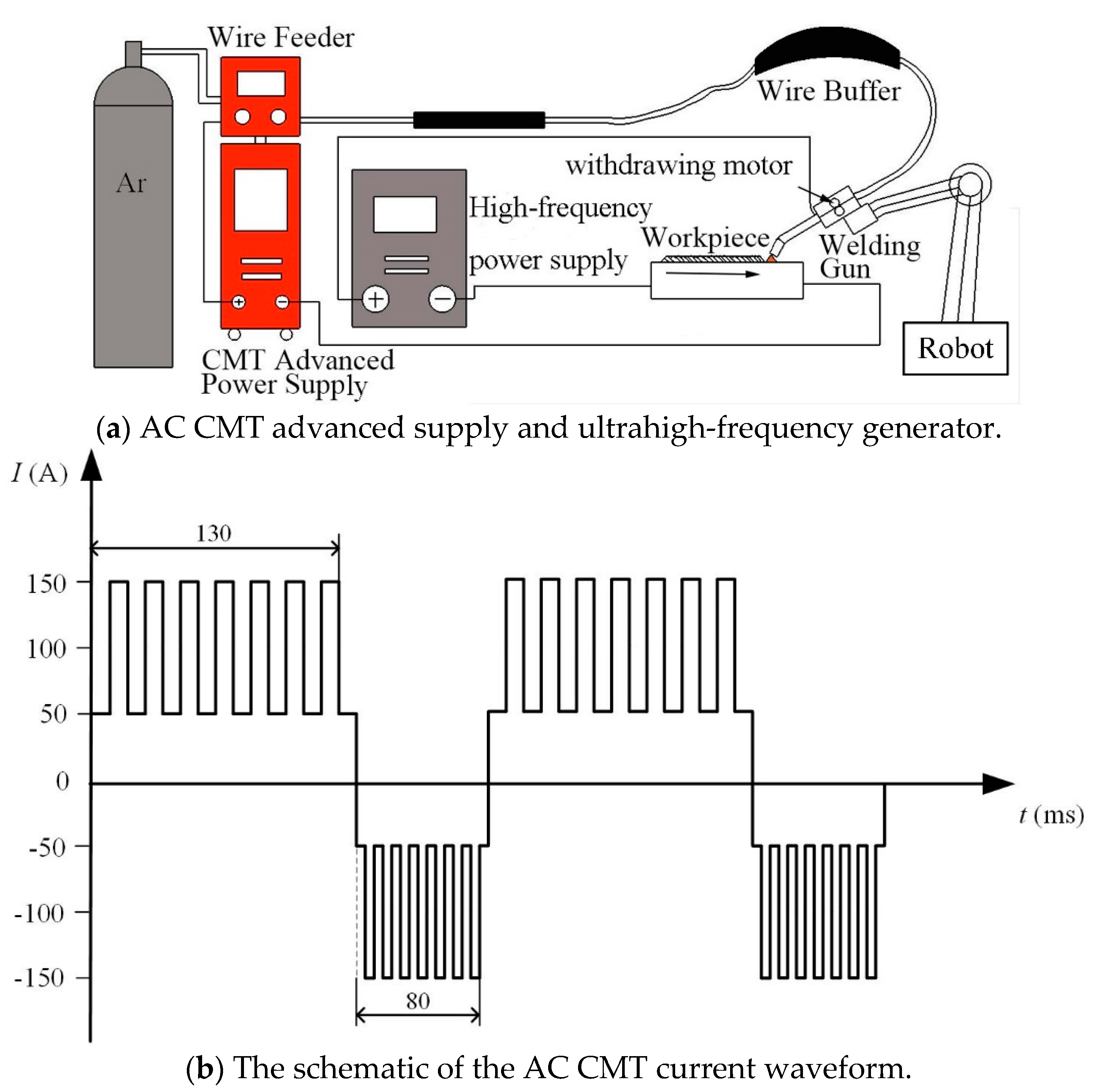
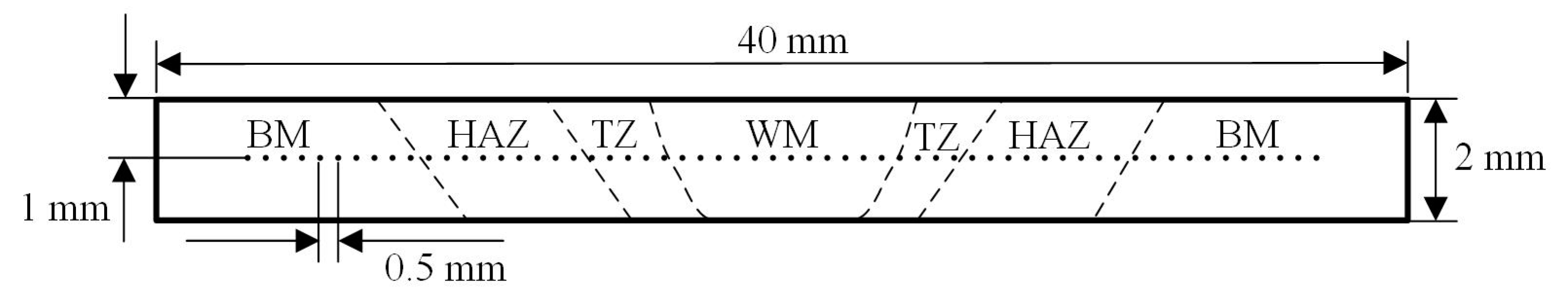
2. Experimental Procedures

Compared to the conventional welding methods, the AC CMT mode of Fronius CMT Advanced 4000 machine has welding currents in electrode positive (EP) phase and electrode negative (EN) phase. There are significant differences between EP and EN phases. In the EP phase, Ar ions hit the molten pool and surface of the work piece, which can quickly clean oxide film on the surface of the workpieces. In the EN phase, the arc is relatively constricted and more heat is redirected to the wire, resulting in fast melting of the wire. Compared with EN phase, arc in EP phase is more divergent and higher heat is imposed on the workpieces, which will increase heat-input and improve quality of the welded joints [25,26,27]. In this study, the welding current in EP phase was therefore selected to couple with pulse current of ultrahigh-frequency to improve the arc characteristics. Two relatively independent power systems were connected in a parallel way, and then linked to the same welding gun held by the KUKA KR60 robot, as shown in Figure 1a. The current waveform of AC CMT is shown in Figure 1b, the average current I of AC CMT is 100 A. The base current Ib of ultrahigh-frequency pulse alternating current with cold metal transfer (UHF-ACCMT, UHF100, HEBUST, Shijiazhuang, China) is 85 A, the peak current Ip of UHF-ACCMT is 30 A, duty cycle δ is 50%, and frequency are 20 kHz, 30 kHz, 40 kHz, 50 kHz, 60 kHz, 70 kHz and 80 kHz, respectively. Therefore, the total current of UHF-ACCMT It = Ib + Ip × δ = I. The specific parameters are listed in Table 1.
2198-T8 Al-Li alloy plates in size of 135 mm × 95 mm × 2 mm and aluminum-silicon (Al-Si) wire ER4043 with a diameter of 1.2 mm were used as the base material and the additional welding wire. The ER4043 wire can provide a large number of Al-Si eutectics during welding [28]. Eutectics have good filling capacity of reducing hot cracks [29]. In order to eliminate macropores effectively, oxide film on both sides of the butt with square welding groove and without root gap (at least 0.15 mm thickness) was cleaned using wire brush and scraper, and grease as well as water stains were erased with acetone [30]. Chemical composition of 2198 Al-Li alloy and Al-Si wire ER4043 are listed in Table 2. Flat welding, using guide arc plate and crater arc plate and shielding gas of pure argon, was adopted.
The optical microstructure of the welded joints was investigated using German Zeiss microscope of Axiovert.A1. The samples were grinded, polished and then etched with Keller reagent (2.5% HNO3 + 1.5% HCL +1.0% HF +95% H2O, volume percentage). Vickers microhardness test was carried out with a 100 g load and 15 s dwell time. Data were acquired with a distance of 0.5 mm across the mid-depth longitudinal section of the welded joints. Tensile tests were performed under the standard of ISO 4136: 2001 on SANS CMT5204 electronic universal testing machine (Shenzhen, China) at a speed of 1 mm/min. Dimension of the tensile samples is shown in Figure 2.

3. Results and Discussion

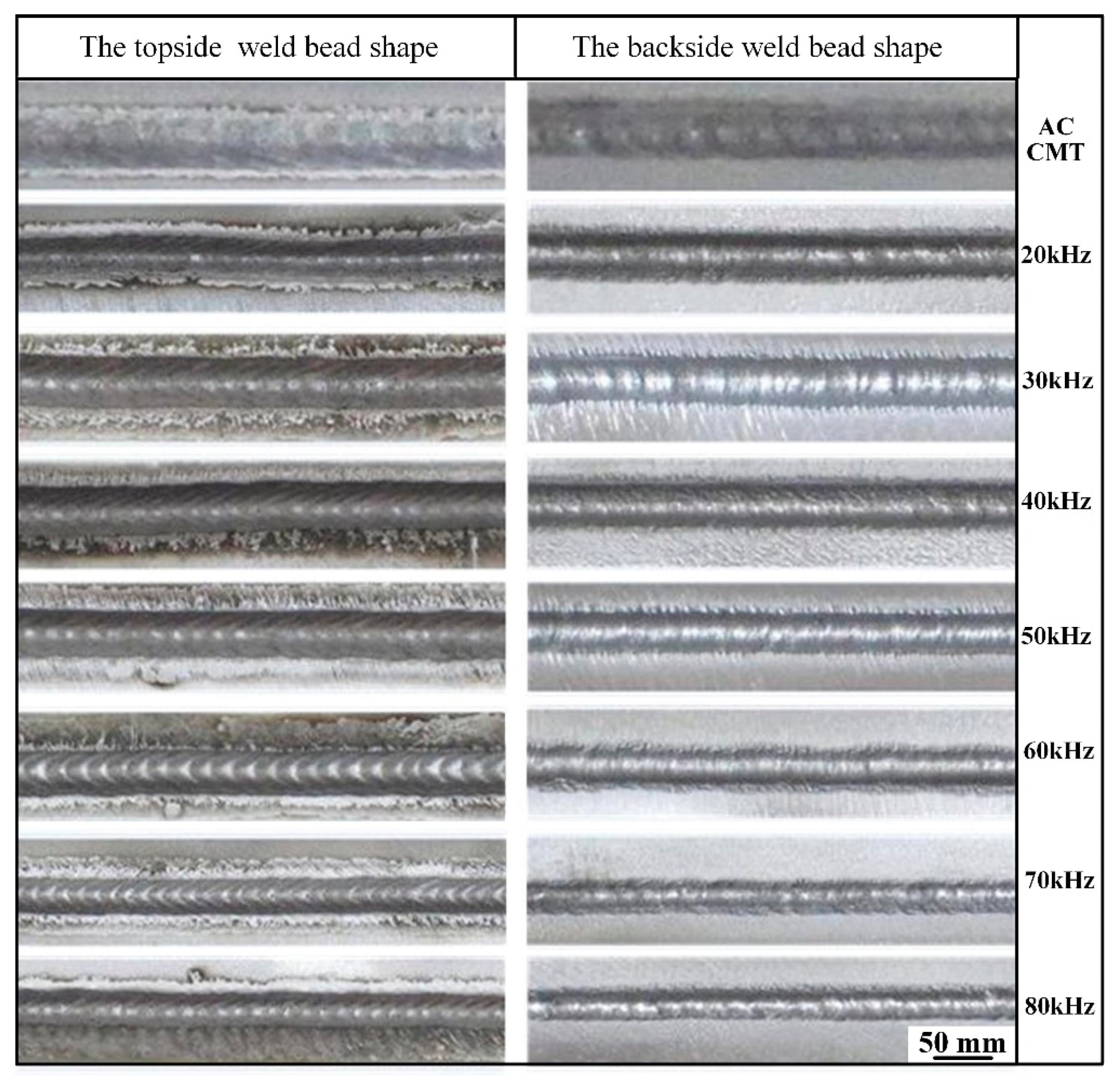
3.1. Macroscopic Morphology of the Welded Joints

Figure 3 shows the welds appearance of 2198 Al-Li alloy welded by AC CMT coupled with ultrahigh-frequency pulse current. Compared with AC CMT process, the base materials exhibit less deformation and surface of the joints are smooth and homogeneous by AC CMT coupled with ultrahigh-frequency pulse current. Metallic luster and uniform ripples can be seen on the welds surface. There are no concave, undercut, weld beading, incomplete penetration, slag or other visual defects. However, the welds appearance have obviously changed with varying frequency, ripples are more obvious and regular by coupling with ultrahigh-frequency current of 60 kHz and 70 kHz, and it almost disappeared at a frequency of 20 kHz. With other ultrahigh-frequency current, ripples have been weakened by different degrees.
According to the electromagnetic theory, the coupled ultrahigh-frequency current generated arc force, which plays a part in stirring the liquid metal in molten pool [31]. The flow form and flow rate of liquid metal are determined under the combined action of surface tension and electromagnetic force, so the solidification morphology of molten pool is different with varying pulse current at different frequency.

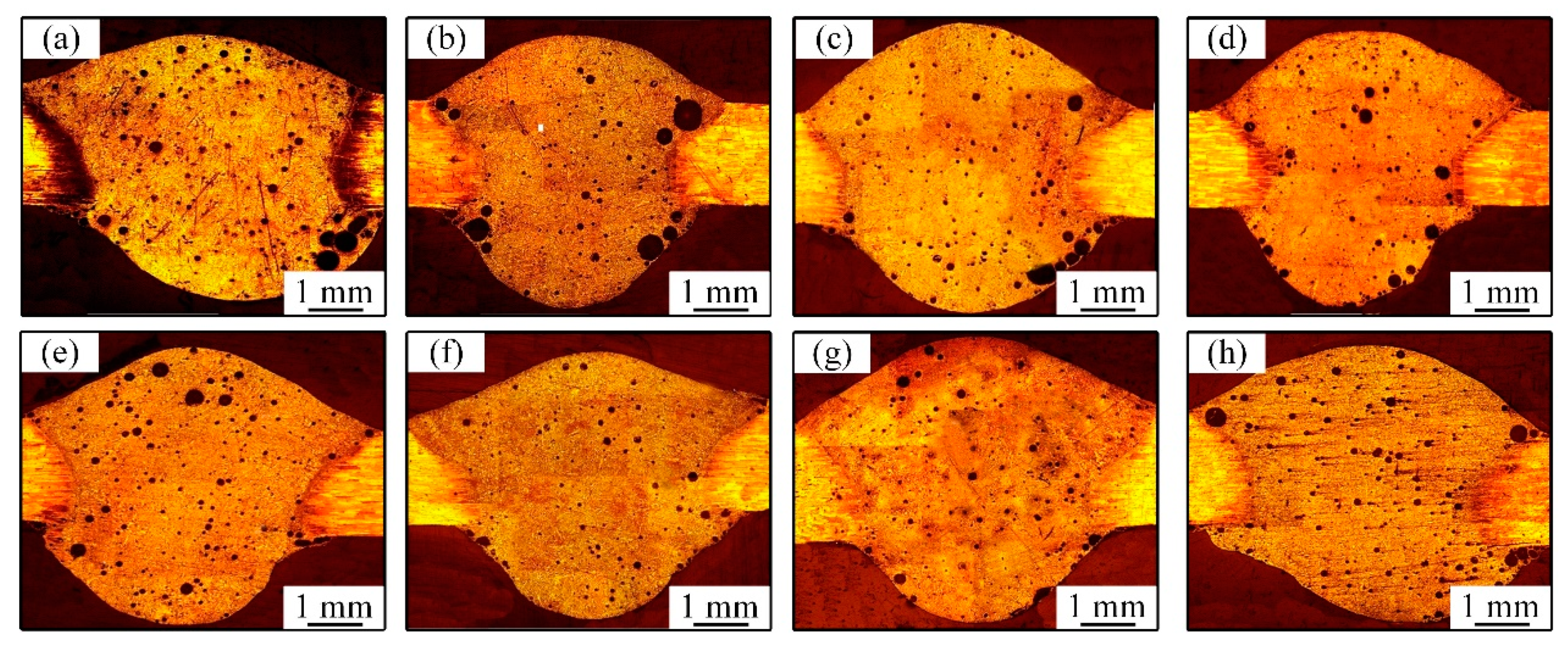
3.2. Pores in Welded Joints

Figure 4 shows the distribution of pores in welded joints. The pores were mainly hydrogen hole, which was difficult to eliminate during welding of Al-Li alloys [31,32,33,34]. It is known that the production of welding pores was attributed to the fact that hydrogen in liquid droplet cannot grow up and overflow due to the low heat input and quick solidification of molten pool during CMT welding. On the one hand, the purity of argon, the cleaning degree of work piece before welding and the high environment humidity were the possible reason of excessive porosity in this study. Figure 4a shows the pores distribution in welded joints welded by AC CMT, in which many pores have relatively large size and are distributed randomly in the welded joints. Figure 4b–d show the pores’ distribution in welded joints welded by AC CMT coupled current at frequency of 20 kHz, 30 kHz, and 40 kHz, respectively. The total number as well as the size of pores presented a decreasing trend. The bigger pores are mainly distributed in the edge of the welded joints, the smaller pores were seen mainly in the middle of the welded joints. Figure 4e–h show the pore distribution in welded joints welded by AC CMT coupled current at frequency of 50 kHz, 60 kHz, 70 kHz, and 80 kHz, respectively. It is seen that the number of pores became smaller and the size of pores became much smaller. A small number of little ones existed in the middle of the welded joints, the bigger pores existed in the edge of the welded joints. A small number fraction of pores is shown in Figure 4f with the coupled ultrahigh-frequency pulse current at a frequency of 60 kHz. According to the standard of ISO-10042:2005, the porosity of the AC CMT joint is 3%, which is D grade (Figure 4a). The joint welded by AC CMT coupled current at frequency of 60 kHz has only a porosity of 1%, which is B grade (Figure 4f). Compared with AC CMT, the porosity and pore diameter of UHF-ACCMT were significantly reduced.
The coupled ultrahigh-frequency pulse current generated electromagnetic force that played an important role in stirring the liquid metal in molten pool. Meanwhile, Si is a strong surface active element in ER4043 that makes the surface tension of liquid metal directly proportional to temperature gradient [35]. The liquid metal was driven by electromagnetic force and surface tension, then it flowed down along the center of molten pool and up along the edge of molten pool, as shown in Figure 5. It benefited the bubbles escaping and reducing the tendency of weld porosity when the direction of fluid flow was consistent with the rise of bubbles. The number fraction of porosity was the minimum when the frequency was 60 kHz.

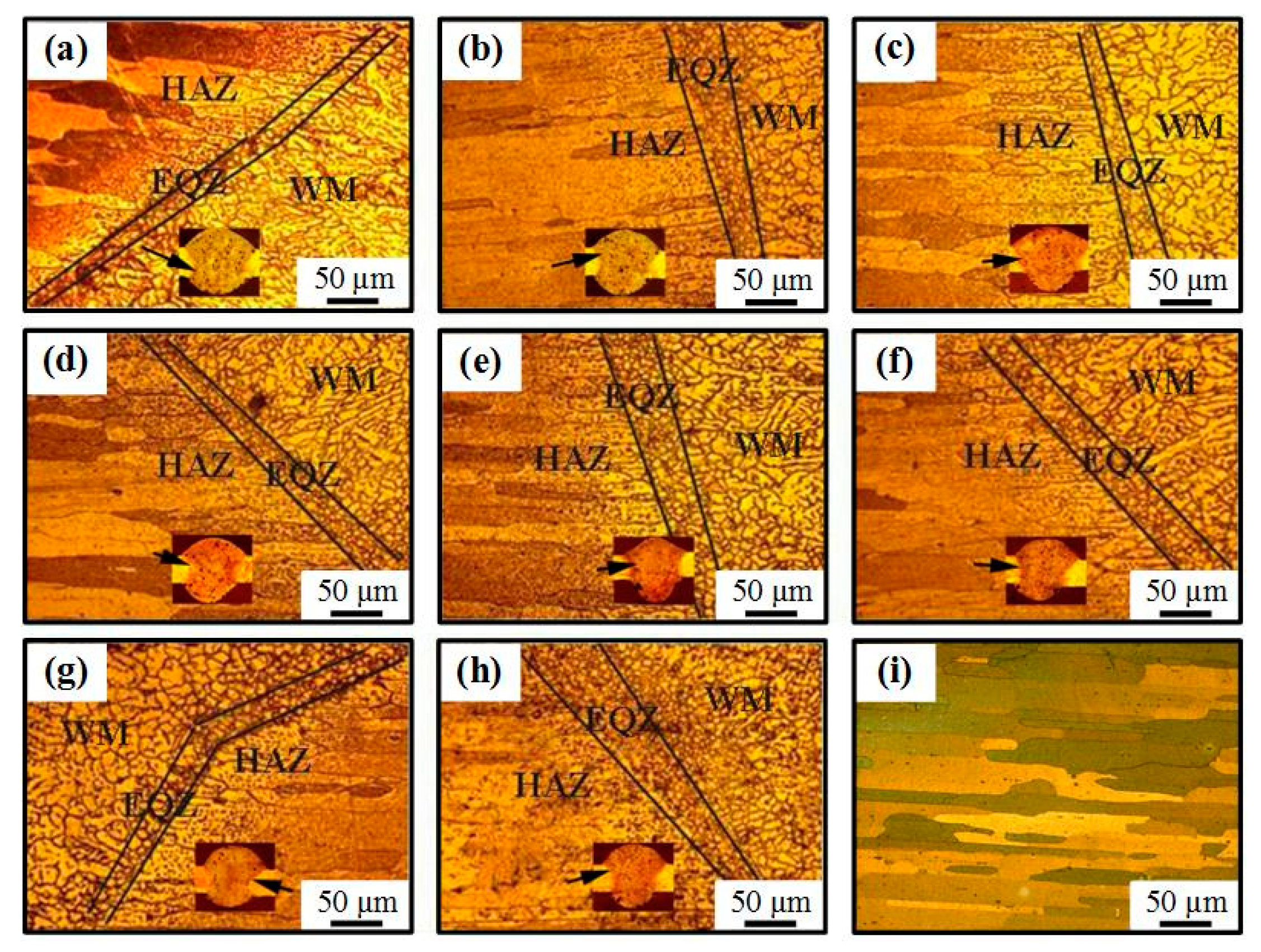
3.3. Microscopic Structure of the Welded Joints

3.3.1. The Microscopic Structure of the Fine Equiaxed Grain Zone (EQZ)

Figure 6 shows the optical microstructure of the welded joints and base metal (BM). Compared to the heat affected zone (HAZ) and weld metal (WM), the EQZ welded by AC CMT is composed of fine equiaxed grains, as shown in Figure 6a. Lin et al. [36] found that the region was not only recrystallized, but also the region was affected by the tiny particles in the base material, such as Al3Ti and Al3Zr, which provided a large number of heterogeneous nucleation sites during the solidification that promoted the formation of heterogeneous nucleation in the EQZ [36].
The width of fine EQZ became bigger when coupled with the ultrahigh-frequency pulse current, as seen from Figure 6b–h. The coupled ultrahigh-frequency current flowed through molten pool. A high frequency pulsed electromagnetic field was generated inside molten pool. Under the high frequency pulsed electromagnetic force, the liquid metal presented periodic vortex motion which scoured the boundary of fusion zone and heat affected zone. Some unfused high melting point particles in the boundary, such as Al3Ti and Al3Zr, appeared in the molten pool and they became the heterogeneous nucleation sites which formed the wider fine EQZ [37,38,39]. The microscopic structure of BM presents lath-shaped along the rolling direction, as shown in Figure 6i.

3.3.2. The Microscopic Structure of the WM

Figure 7 shows the optical microstructure of WM. It was coarse dendrite grains in the WM of the welded joints welded by AC CMT, as shown in Figure 7a. When 2198 Al-Li alloy was welded by AC CMT coupled ultrahigh-frequency current, grain refinement occurred obviously in the WM, as shown in Figure 7b–h. The equiaxed dendrite grains appeared in the WM at a frequency of 20 kHz in Figure 7b. When the frequency of pulse current is 30 kHz and 40 kHz, the fine equiaxed non-dendrite grains appeared in the WM, alternating with the distribution of equiaxed dendrite grains in the middle of the weld, as shown in Figure 7c,d. Micrographs of the WMs in Figure 7e–g show that a large amount of fine equiaxed non-dendrite grains are non-uniformly distributed in the WM at frequency of 50 kHz, 60 kHz and 70 kHz, respectively. However, when the frequency exceeds 70 kHz, grain refinement began to weaken, the number fraction of the equiaxed non-dendrite structures reduced, and there are mainly equiaxed dendrites in WM (Figure 7h).
The electromagnetic force generated by the coupled ultrahigh-frequency current played a major role in stirring the liquid metal in molten pool, which can effectively break new grains and provide the sites of heterogeneous nucleation [23]. On the other hand, some high melting point particles, such as Al3Ti and Al3Zr, were involved into molten pool under the action of liquid metal scouring, which provided the sites of the heterogeneous nucleation [37,38,39]. In addition, according to the principle of metal crystallization thermodynamics, the regular flow of liquid metal in molten pool was conducive to promoting the homogeneity of liquid metal temperature, which can effectively reduce the temperature gradient at the front of the solid-liquid interface and enhance component undercooling [40]. The increase of undercooling promoted the microstructure transformation of WM from coarse dendrite grains to fine equiaxed grains, which significantly played a role in grain refinement.

3.4. Mechanical Properties of the Welded Joints

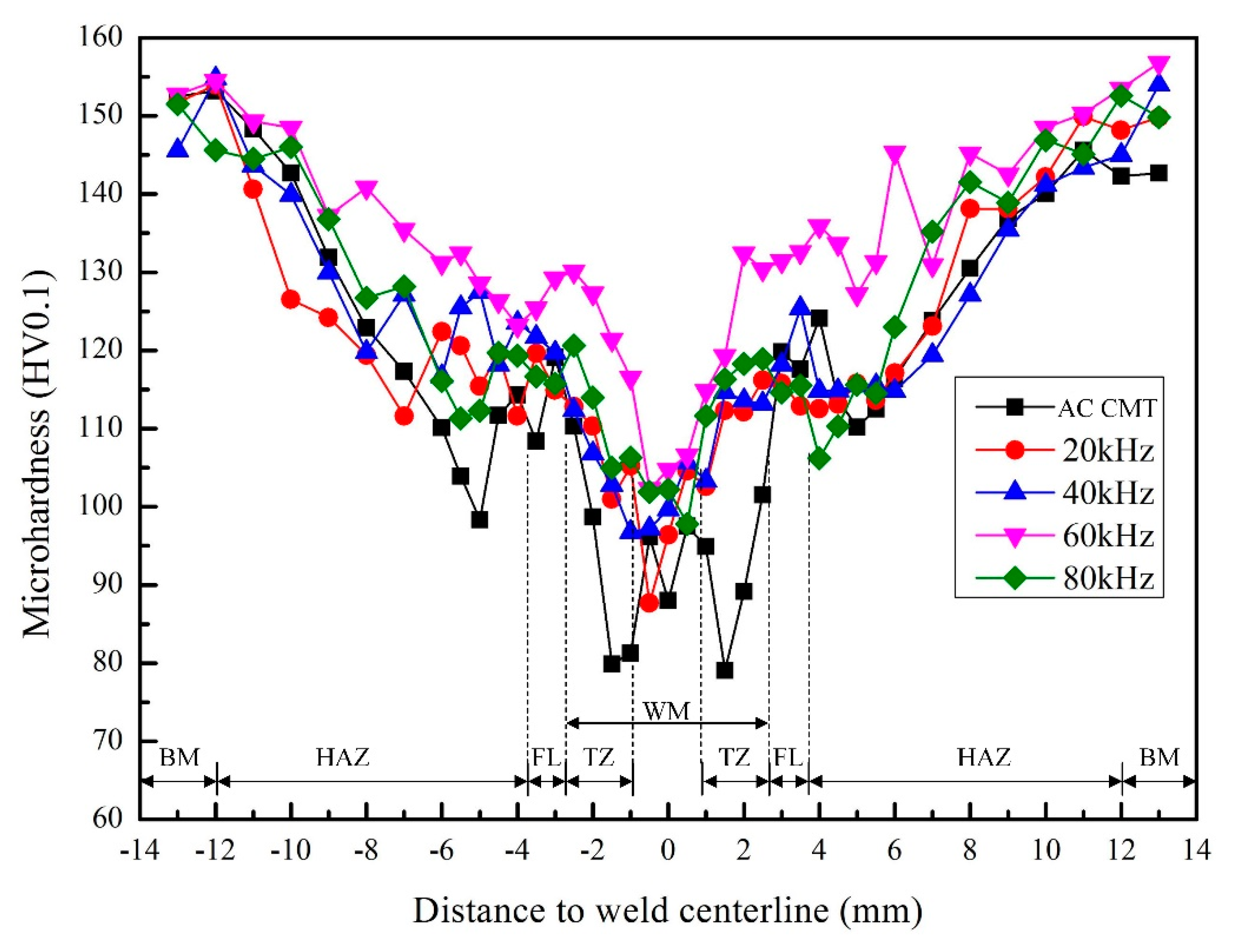
3.4.1. Microhardness of the Welded Joints

Three samples of different processes were prepared for microhardness testing. The microhardness measuring points are shown in Figure 8. Figure 9 shows the averaged microhardness distribution of the welded joints. The microhardness curves had the similar variation tendency with different frequency of pulse current. The microhardness of base material (BM) was the highest, about 150 HV0.1. The microhardness decreases gradually from the base material (BM) to the fusion line (FL). The microhardness of weld center was higher than that of FL. The microhardness of the transition zone (TZ) between the weld metal (WM) and the FL was the lowest which became the weakest zone of the welded joints. When coupled with ultrahigh-frequency pulse currents, the microhardness in different regions was higher than that of uncoupled ultrahigh-frequency pulse current. Such as, the microhardness in weld center increased from 88 HV0.1 to 104 HV0.1. When the frequency of coupled pulse current was 60 kHz, the average microhardness of WM was the highest, 116 HV0.1. The increase of microhardness was related to the grain refinement, which was obvious when the coupled frequency was 60 kHz, especially, the finer grains correspond to the highest microhardness of the WM [41,42]. The transition zone between the WM and the FL is the softening zone where the metal experienced overaging caused by the thermal cycle and the strengthening phase particles agglomerated. Therefore, the coherent relationship between precipitated phase and parent phase was destroyed, resulting in an increase in size and a decrease in the number of precipitated strengthening phases within the grains, which decreases the microhardness of softening zone [43].

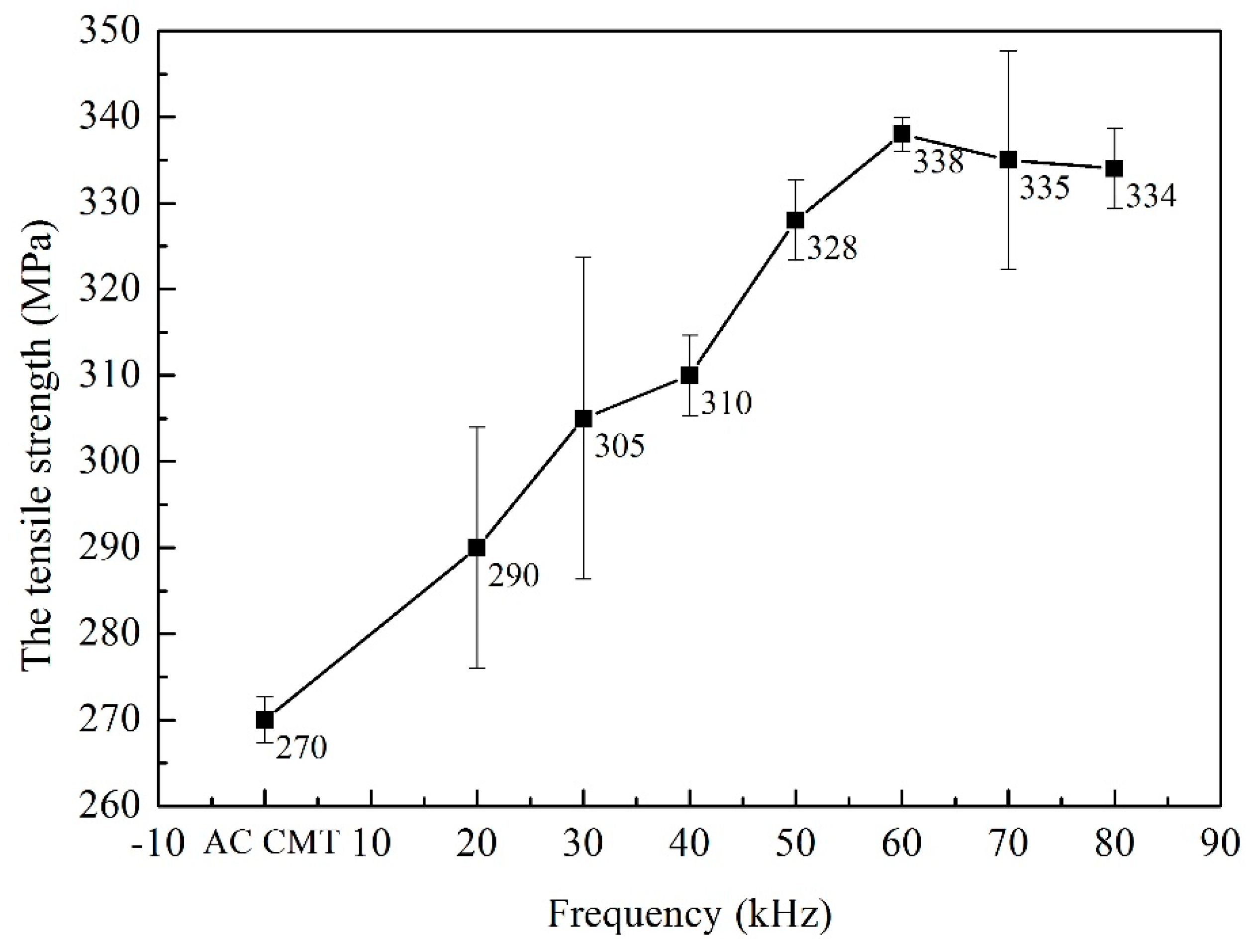
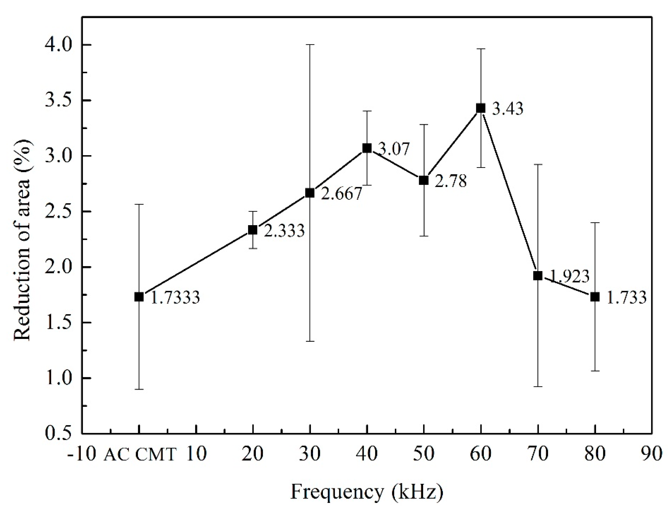
3.4.2. Tensile Properties of the Welded Joints

Three tensile test samples of different processes were prepared. The fractures occurred at the fusion line. The tensile strength, yield strength and reduction of area of the welded joints were shown in Figure 10, Figure 11 and Figure 12. As shown in Figure 10, the tensile strength of the welded joints uncoupled with ultrahigh-frequency pulse current was 270 MPa which was only 57.4% of the base material (BM, 470 MPa). The fracture presented the characteristics of intergranular fracture, as shown in Figure 13a.The tensile strength of the welded joints increased significantly with the increasing of pulse frequency (Figure 10). When the frequency was 60 kHz, because of the wider fine EQZ and finer equiaxed non-dendrite grains in the WM, tensile strength of the joint reached up the highest value, 338 MPa. As shown in Figure 13f, a large amount of tear ridges was observed at the fractured surface and the fractured mode is the quasi-cleavage fracture. The cavities inside grains and impurities are the quasi cleavage crack source. The change of yield strength and reduction of area were similar to the tensile strength as shown in Figure 11 and Figure 12.

4. Conclusions

In this study, 2198 Al-Li alloy was welded using UHF-ACCMT. Influence of different ultrahigh-frequency on the formation, porosity, microstructure, microhardness and tensile strength of the welded joints were investigated. Conclusions are drawn as follows:
(1)
According to the electromagnetic theory, the coupled ultrahigh-frequency current generated electromagnetic force which played a part in stirring the liquid metal in molten pool. The welded joints were smooth and homogeneous; metallic luster and uniform ripples can be seen on the welds surface when the frequency of coupled pulse current were 60 kHz and 70 kHz.
(2)
Under the action of electromagnetic force and surface tension, the flowing liquid metal was conducive to bubbles escaping. The size and number of the weld pores decreased with the increase of coupled current frequency. The porosity was the minimum when the frequency was 60 kHz.
(3)
The molten pool was scoured and stirred by the electromagnetic force which provided the sites of heterogeneous nucleation for the nucleation and grain refinement. The width of fine EQZ became larger, and a large amount of equiaxed non-dendrite grains was observed in the WM at frequency of 50 kHz, 60 kHz, and 70 kHz, respectively.
(4)
When the frequency of the coupled pulse current was 60 kHz, the weld porosity was the minimum and grain size in WM were the smallest. The average microhardness of WM and tensile strength of the welded joints were the highest, 116 HV0.1 and 338 MPa, respectively. The fracture mode of the welded joints is quasi-cleavage fracture.

Author Contributions

Data curation, Y.S.; Formal analysis, Z.L.; Investigation, C.W.; Project administration, D.W.; Writing–original draft, L.W.; Writing–review & editing, L.W.

Funding

This research was funded by National Natural Science Foundation of China, grant number 51875168 and The APC was funded by National Natural Science Foundation of China, grant number 51875168.

Acknowledgments

This work was supported by National Natural Science Foundation of China (Grant No. 51875168), Natural Science Foundation of Hebei Province (Grant No. E2016208077) and Hebei Education Department Foundation (Grant No. QN2018003).

Conflicts of Interest

The authors declare no conflict of interest.

References

  1. Williams, J.C.; Starke, E.A. Progress in structural materials for aerospace systems. Acta. Mater. 2003, 51, 5775–5799. [Google Scholar] [CrossRef]
  2. Rioja, R.J.; Liu, J. The evolution of Al-Li base products for aerospace and space applications. Metall. Mater. Trans. A 2012, 43, 3325–3337. [Google Scholar] [CrossRef]
  3. Padmanabham, G.; Pandey, S.; Schaper, M. Pulsed gas metal arc welding of Al-Cu-Li alloy. Sci. Technol. Weld. Join. 2005, 10, 67–75. [Google Scholar] [CrossRef]
  4. Xiao, R.; Zhang, X. Problems and issues in laser beam welding of aluminum–lithium alloys. J. Manuf. Process. 2014, 16, 166–175. [Google Scholar] [CrossRef]
  5. Wei, S.; Hao, C.; Chen, J. Study of friction stir welding of 1420 aluminum–lithium alloy. Mater. Sci. Eng. A 2007, 452, 170–177. [Google Scholar] [CrossRef]
  6. Yang, M.C.; Sun, Z.; Rui, M.A. Analysis for microstructure and precipitation phase evolution of friction stir welding 2060 butt joint. Mater. Sci. Technol. 2014, 22, 118–122. [Google Scholar]
  7. Chang, C.C.; Chou, C.P.; Hsu, S.N.; Hsiung, G.Y. Effect of laser welding on properties of dissimilar joint of Al-Mg-Si and Al-Mn aluminum alloys. J. Mater. Sci. Technol. 2010, 26, 276–282. [Google Scholar] [CrossRef]
  8. Gibson, B.T.; Ballun, M.C.; Cook, G.E. Friction stir lap joining of 2198 aluminum–lithium alloy with weaving and pulsing variants. J. Manuf. Process. 2015, 18, 12–22. [Google Scholar] [CrossRef]
  9. Chang, W.S.; Rajesh, S.R.; Chun, C.K. Microstructure and mechanical properties of hybrid laser-friction stir welding between AA6061-T6 Al alloy and AZ31 Mg alloy. J. Mater. Sci. Technol. 2011, 27, 199–204. [Google Scholar] [CrossRef]
  10. Tian, Y.T.; Robson, J.D.; Riekehr, S.; Kashaev, N.; Wang, L.; Lowe, T.; Karanika, A. Process optimization of dual-laser beam welding of advanced Al-Li alloys through hot cracking susceptibility modeling. Metall. Mater. Trans. A 2016, 47, 3533–3544. [Google Scholar] [CrossRef]
  11. Han, B.; Chen, Y.B.; Wang, T.; Li, H.; Li, L.Q. Microstructural evolution and interfacial crack corrosion behavior of double-sided laser beam welded 2060/2099 Al-Li alloys T-joints. Mater. Des. 2017, 135, 353–365. [Google Scholar] [CrossRef]
  12. Liang, Y.; Shen, J.Q.; Hu, S.S.; Wang, H.C.; Pang, J. Effect of TIG current on microstructural and mechanical properties of 6061-T6 aluminum alloy joints by TIG-CMT hybrid welding. J. Mater. Process. Tech. 2018, 255, 161–174. [Google Scholar] [CrossRef]
  13. Srikanth, T.; Surendran, S.; Balaganesan, G.; Manjunath, G.L. Response of CMT welded aluminum AA5086-H111 to AA6061-T6 plate with AA4043 filler for ballistic. Procedia Eng. 2017, 194, 522–528. [Google Scholar] [CrossRef]
  14. Shang, J.; Wang, K.H.; Tian, H.J.; Zhou, Q.; Li, G.L. Study on cold metal transfer welded lap joints of Mg/Al dissimilar metals. Trans. China Weld. Inst. 2011, 32, 41–45. [Google Scholar]
  15. Farzadi, A.; Serajzadeh, S.; Kokabi, A.H. Investigation of weld pool in aluminum alloys, geometry and solidification microstructure. Int. J. Therm. Sci. 2010, 49, 809–819. [Google Scholar] [CrossRef]
  16. Faraji, A.H.; Goodarzi, M.; Seyedein, S.H.; Zamani, M.H. Experimental study and numerical modeling of arc and weld pool in stationary GTA welding of pure aluminum. Int. J. Adv. Manuf. Technol. 2014, 71, 2059–2071. [Google Scholar] [CrossRef]
  17. Wang, D.L.; Chen, Y.C.; Li, H.Y.; Liang, Z.M. Effects of AC CMT welding coupled with high-frequency pulse current on microstructure and mechanical properties of 2060 Al-Li alloy joint. J. Hot Work. Technol. 2017, 46, 13–16. [Google Scholar]
  18. Liu, H.B.; Yang, S.L.; Xie, C.J. Microstructure characterization and mechanism of fatigue crack initiation near pores for 6005A CMT welded joint. Metall. Mater. Trans. A 2017, 707, 22–29. [Google Scholar] [CrossRef]
  19. Li, J.; Ma, J.H.; Gao, Y.L.; Zhai, Q.J. Research on solidification structure refinement of pure aluminum by electric current pulse with parallel electrodes. Mater. Sci. Eng. A 2008, 490, 452–456. [Google Scholar] [CrossRef]
  20. Yang, M.X.; Qi, B.J.; Cong, B.Q.; Liu, F.J.; Yang, Z. Effect of pulse frequency on microstructure and properties of Ti-6Al-4V by ultrahigh-frequency pulse gas tungsten arc welding. Int. J. Adv. Manuf. Technol. 2013, 68, 19–31. [Google Scholar] [CrossRef]
  21. Huang, Y.H.; Yuan, Z.M. Micro-structure and low temperature toughness in welding zone of X65 high-frequency welding pipe. J. Dalian Marit. Univ. 2010, 36, 104–106. [Google Scholar]
  22. Hao, H.; Lu, G.Q.; Wang, F.Y.; Zhang, X.G. Effects of electromagnetic stirring on solidification of metal foams. J. Iron Steel Res. 2012, S1, 195–198. [Google Scholar]
  23. Yang, M.X.; Zheng, H.; Qi, B.J.; Yang, Z. Microstructure and fatigue property of Ti-6Al-4V by ultrahigh frequency pulse welding. J. Manuf. Sci. Eng. 2016, 139, 041015. [Google Scholar] [CrossRef]
  24. Wan, X.H.; Zhao, H.T.; Jin, J.L. High frequency pulse tungsten arc welding process trials of TA15 titanium alloy. Aeronaut. Manuf. Technol. 2017, 7, 82–85. [Google Scholar]
  25. Feng, J.C.; Zhang, H.T.; He, P. The CMT short-circuiting metal transfer process and its use in thin aluminum sheets welding. Mater. Des. 2009, 30, 1850–1852. [Google Scholar] [CrossRef]
  26. Zhang, Y.; Yang, J.G.; Liu, X.S.; Fang, H.Y. Welding TC4 thin plates by revolution pressing in welding process. Trans. China Weld. Inst. 2010, 31, 81–84. [Google Scholar]
  27. Ellis, M.B.D. Fusion welding of aluminum-lithium alloys. Weld. Metal. Fabr. 1996, 64, 55–60. [Google Scholar]
  28. Diao, G.Y.; Wang, D.L.; Li, H.C.; Liang, Z.M. Effects of different welding wires on microstructure and mechanical properties of Al-Zn-Mg series aluminum alloy pulsed MIG welds. J. Hot Work. Technol. 2018, 47, 195–197. [Google Scholar]
  29. Paramo, V.; Colas, R.; Velasco, E.; Valtierra, S. Spheroidization of the Al-Si eutectic in a cast aluminum alloy. J. Mater. Eng. Perform. 2000, 9, 616–622. [Google Scholar] [CrossRef]
  30. Chen, K.; Yang, W.X.; Xiao, R.S. Direct laser welding of an Al- Li alloy plate without prior surface cleaning. Laser Eng. 2011, 22, 361–369. [Google Scholar]
  31. Xiao, R.; Yang, W.; Chen, K. Porosity characterization in laser welds of Al-Li alloy 1420. Appl. Laser 2007, 27, 13–17. [Google Scholar]
  32. Tang, L.X.; Xiao, Y.; Lan, Z.G.; Fan, X.L.; Li, Y.F. Porosity prevention in MIG welding aluminum and aluminum alloy. Weld. Dig. Mach. Manuf. 2011, 5, 35–39. [Google Scholar]
  33. Wang, Z.; Oliveira, J.P.; Zeng, Z. Laser beam oscillating welding of 5A06 aluminum alloys: Microstructure, porosity and mechanical properties. Opt. Laser Technol. 2019, 111, 58–65. [Google Scholar] [CrossRef]
  34. Fan, Z.P. Effect of surface state of aluminum alloy on welding pores. Aerosp. Manuf. Technol. 2000, 2, 19–23. [Google Scholar]
  35. Huang, Y.; Fan, D. Mechanism of weld penetration increase of AC A-TIG welding for aluminum alloy. Weld. Join. 2003, 4, 9–11. [Google Scholar]
  36. Lin, D.C.; Wang, G.X.; Srivatsan, T.S. A mechanism for the formation of equiaxed grains in welds of aluminum-lithium alloy 2090. Mater. Sci. Eng. A 2003, 351, 304–309. [Google Scholar] [CrossRef]
  37. Gupta, R.K.; Niraj, N.; Nagasireesha, G. Development and characterization of Al-Li alloys. Mater. Sci. Eng. A 2006, 420, 228–234. [Google Scholar] [CrossRef]
  38. Liao, M. Dislocation theory based short crack model and its application for aircraft aluminum alloys. Eng. Fract. Mech. 2010, 77, 22–36. [Google Scholar] [CrossRef]
  39. An, N.; Zhang, X.Y.; Wang, Q.M.; Yang, W.X.; Xiao, R.S. Fiber laser welding of 2060 aluminum-lithium alloy with filler wire. Chin. J. Lasers 2014, 41, 100–105. [Google Scholar]
  40. Wang, D.; He, C.S.; Wang, H.; Zhao, X.; Zuo, L. Joint softening in heat affected zone during metal inert gas welding of Al-12.7Si-0.7Mg alloy. Mater. Res. Innov. 2014, 18, 224–227. [Google Scholar] [CrossRef]
  41. Rajakumar, S.; Muralidharan, C.; Balasubramanian, V. Establishing empirical relationships to predict grain size and tensile strength of friction stir welded AA 6061-T6 aluminium alloy joints. Trans. Nonferr. Metal Soc. 2010, 20, 1863–1872. [Google Scholar] [CrossRef]
  42. Lin, K.L.; Yang, W.X.; Lv, J.X.; Xiao, R.S. Laser beam welding study of 2198-T851 aluminium-lithium alloy. Chin. J. Lasers 2014, 41, 90–95. [Google Scholar]
  43. Dvorna, K.M.J.; Frost, R.H.; Olson, D.L. Influence of solidification kinetics on aluminum weld grain refinement. Weld. J. 1991, 70, 271–276. [Google Scholar]
Figure 1. The experiment installation of AC CMT coupled with ultrahigh-frequency power supply (a) and the schematic of the AC CMT current waveform (b).
Materials 12 00079 g001
Figure 2. Schematic of the tensile sample (mm).
Materials 12 00079 g002
Figure 3. The topside and backside weld bead shape welded by AC CMT and AC CMT coupled current at frequency of 20 kHz, 30 kHz, 40 kHz, 50 kHz, 60 kHz, 70 kHz, and 80 kHz, respectively.
Materials 12 00079 g003
Figure 4. (ah) Distribution of pores in the welded joints welded by (a) AC CMT and (b) AC CMT coupled current at frequency of 20 kHz, (c) 30 kHz, (d) 40 kHz, (e) 50 kHz, (f) 60 kHz, (g) 70 kHz, and (h) 80 kHz, respectively.
Materials 12 00079 g004
Figure 5. Relation between surface tension distribution and liquid metal flow of the molten pool.
Materials 12 00079 g005
Figure 6. (ai) The optical microstructure of the welded joints welded by (a) AC CMT and (b) AC CMT coupled current at frequency of 20 kHz, (c) 30 kHz, (d) 40 kHz, (e) 50 kHz, (f) 60 kHz, (g) 70 kHz, (h) 80 kHz and BM (i), respectively.
Materials 12 00079 g006
Figure 7. (ah) The optical microstructure of WM welded by (a) AC CMT and (b) AC CMT coupled current at frequency of 20 kHz, (c) 30 kHz, (d) 40 kHz, (h) 50 kHz, (e) 60 kHz, (f) 70 kHz, and (h) 80 kHz, respectively.
Materials 12 00079 g007
Figure 8. Schematic drawing of microhardness measuring points.
Materials 12 00079 g008
Figure 9. Microhardness distribution of the welded joints welded by AC CMT and AC CMT coupled current at frequency of 20 kHz, 40 kHz, 60 kHz, and 80 kHz, respectively.
Materials 12 00079 g009
Figure 10. The tensile strength of joints welded by AC CMT and AC CMT coupled current at frequency of 20 kHz, 30 kHz, 40 kHz, 50 kHz, 60 kHz, 70 kHz and 80 kHz, respectively.
Materials 12 00079 g010
Figure 11. The yield strength of joints welded by AC CMT and AC CMT coupled current at frequency of 20 kHz, 30 kHz, 40 kHz, 50 kHz, 60 kHz, 70 kHz and 80 kHz, respectively.
Materials 12 00079 g011
Figure 12. The reduction of area of joints welded by AC CMT and AC CMT coupled current at frequency of 20 kHz, 30 kHz, 40 kHz, 50 kHz, 60 kHz, 70 kHz and 80 kHz, respectively.
Materials 12 00079 g012
Figure 13. (ah) SEM fracture surface welded by (a) AC CMT and (b) AC CMT coupled with the frequency of 20 kHz, (c) 30 kHz, (d) 40 kHz, (e) 50 kHz, (f) 60 kHz, (g) 70 kHz, and (h) 80 kHz, respectively.
Materials 12 00079 g013
Table 1. Process parameters of UHF-ACCMT welding.
Base Current Ib/APulse Current Ip/AWelding Rate v/(cm·min−1)Gas Flow Rate q/(L·min−1)EP Duration (ms)EN Duration (ms)
8530702013080
Table 2. Composition of the base materials and wire (wt %).
MaterialsCuLiZnMnMgSiFeAl
21982.9–3.50.8–1.1≤0.35≤0.50.25–0.8≤0.08≤0.01Bal.
ER40430.3-0.10.050.054.5–6.00.8Bal.

