Application of Plasma Treatment in Preparation of Soybean Oil Factory Sludge Catalyst and Its Application in Selective Catalytic Oxidation (SCO) Denitration

Abstract
:1. Introduction
2. Materials and Methods
2.1. Materials
2.2. Catalyst Pretreatment
2.3. Catalyst Preparation
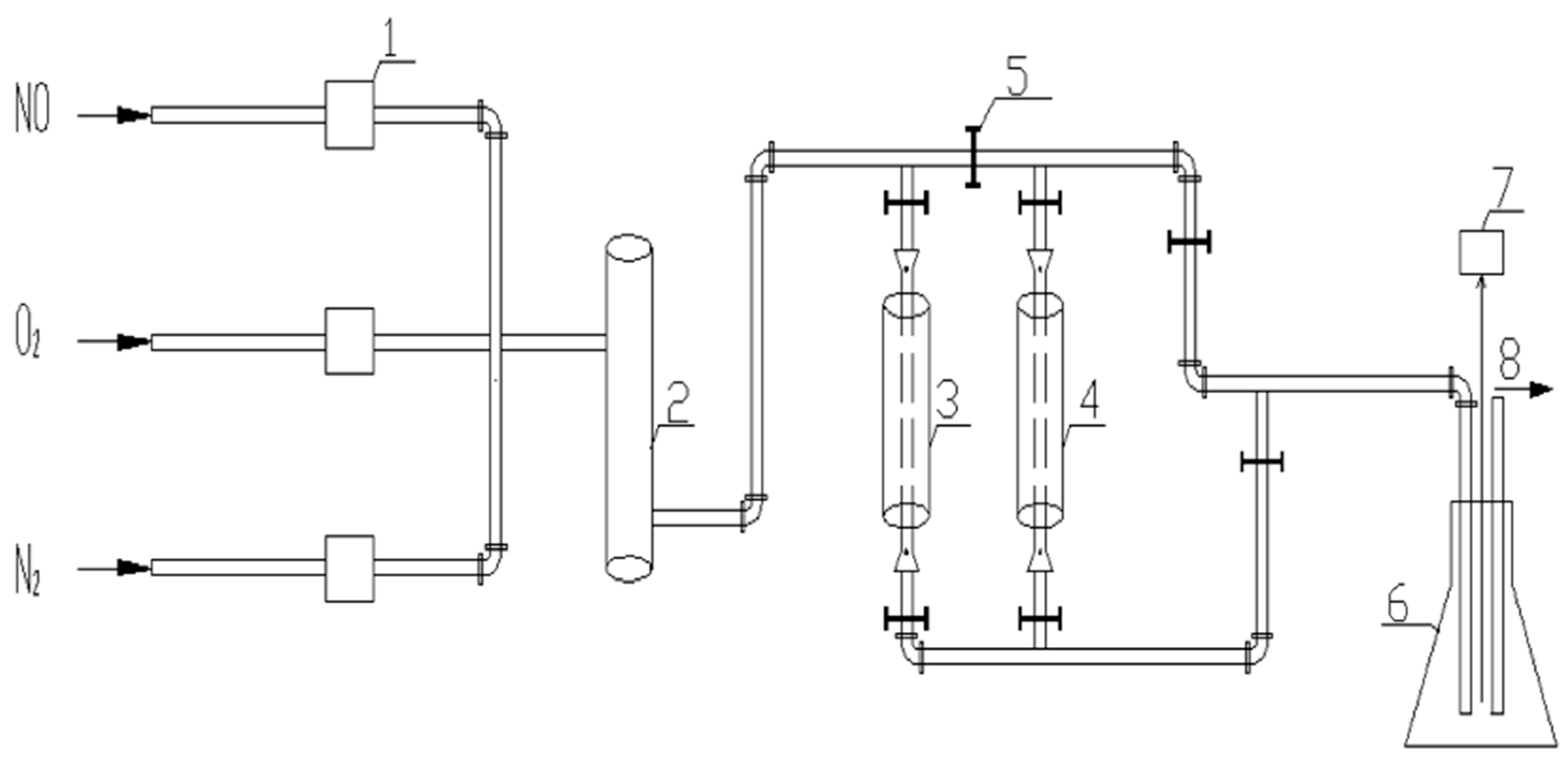
2.4. Catalyst Evaluation Device
3. Results and Discussion
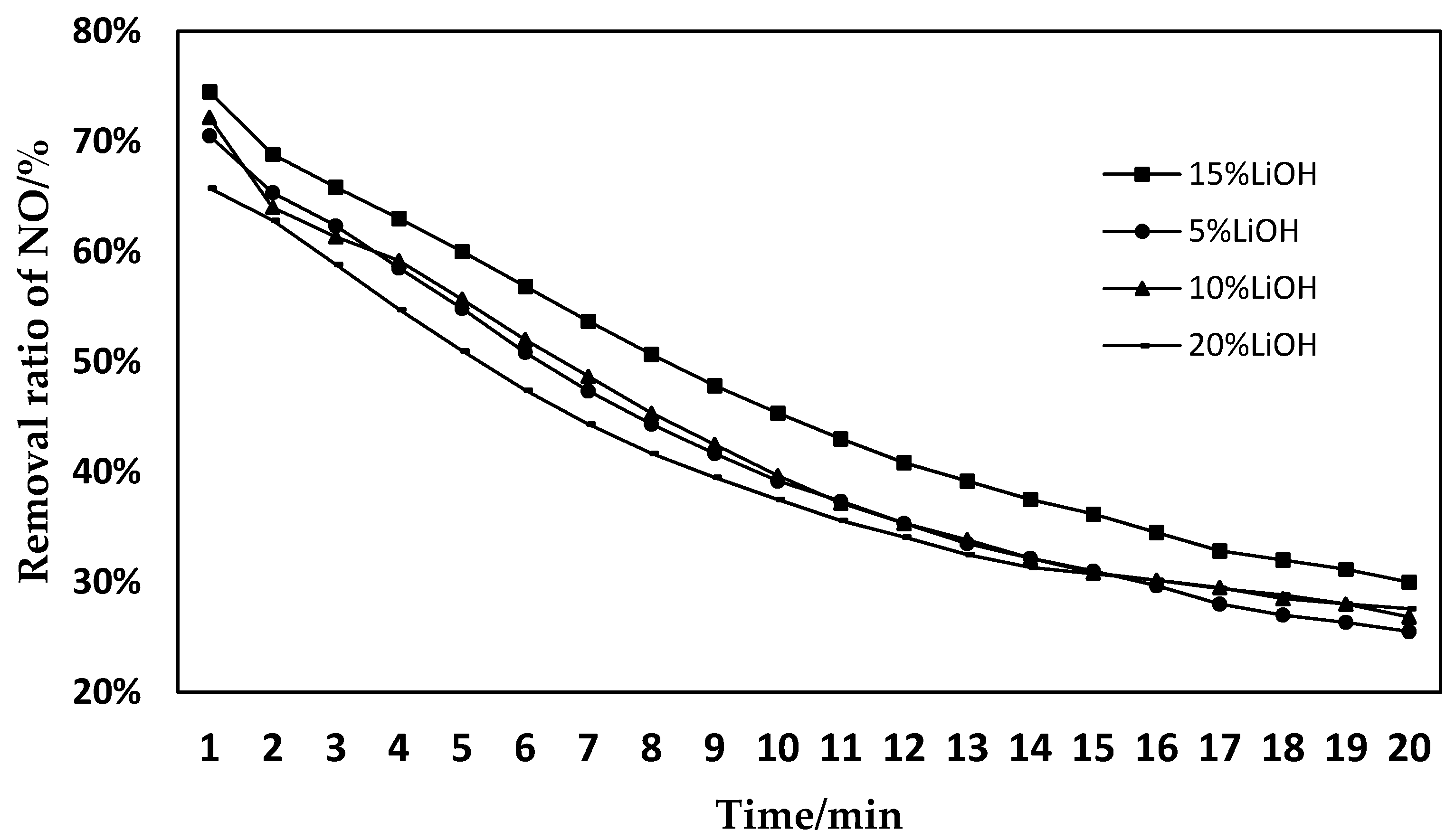
3.1. Effects of Different Activation Concentrations on the Denitration Performance of SCO
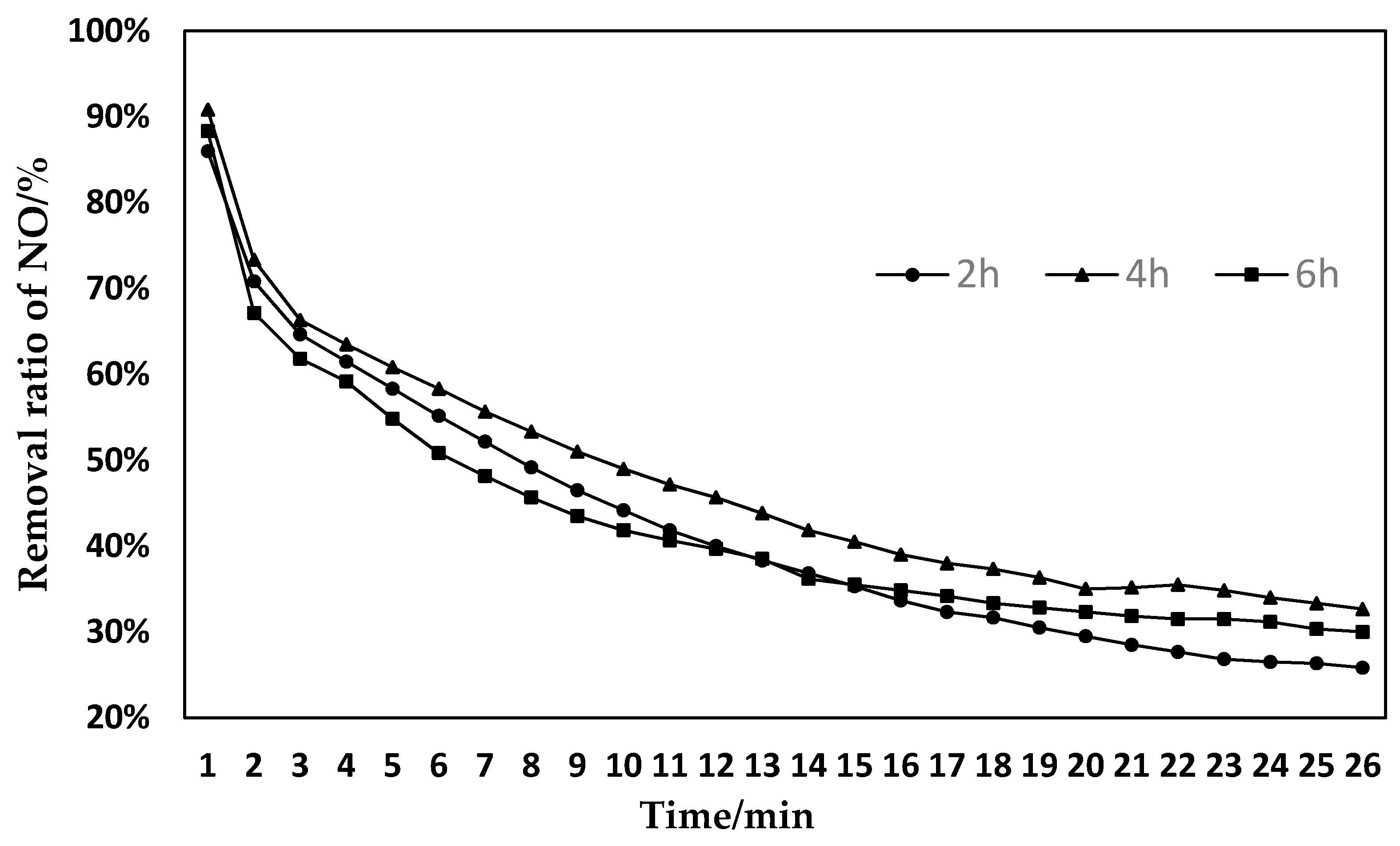
3.2. Effect of Different Activation Times on SCO Denitration Performance
3.3. Effect of Different Preparation Sequences on Catalytic Activity of Catalysts
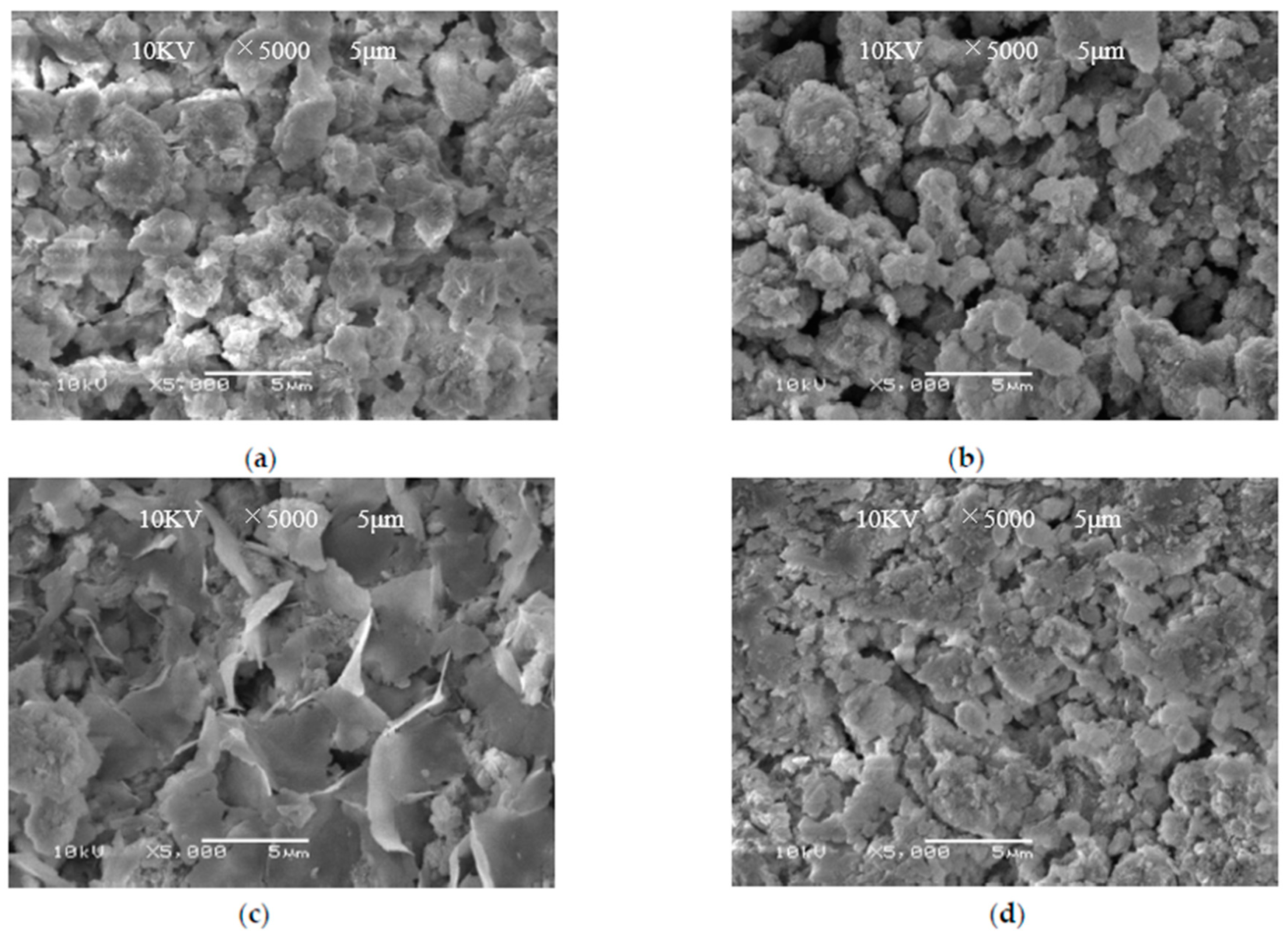
4. Characterization
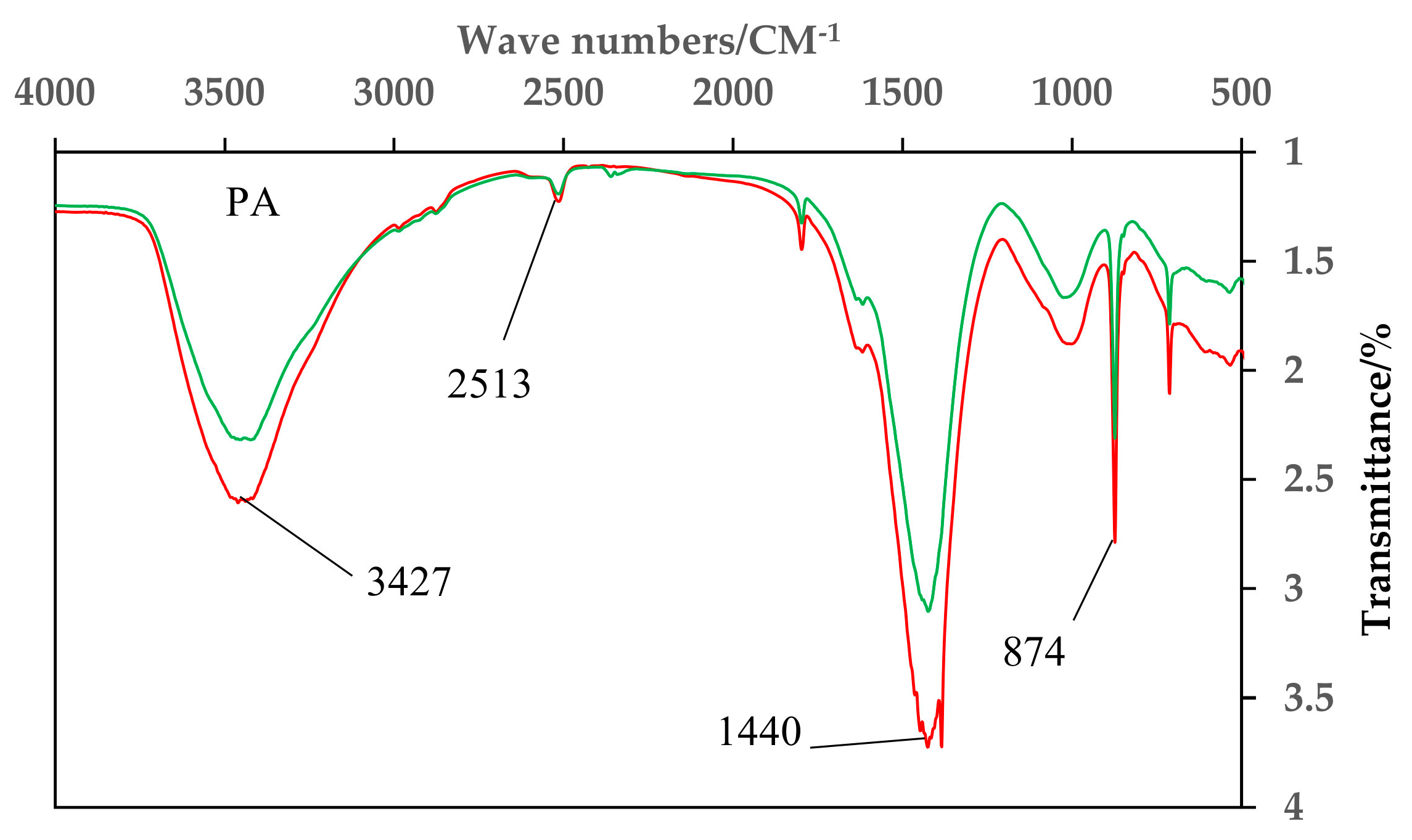
4.1. Infrared Spectrum Analysis
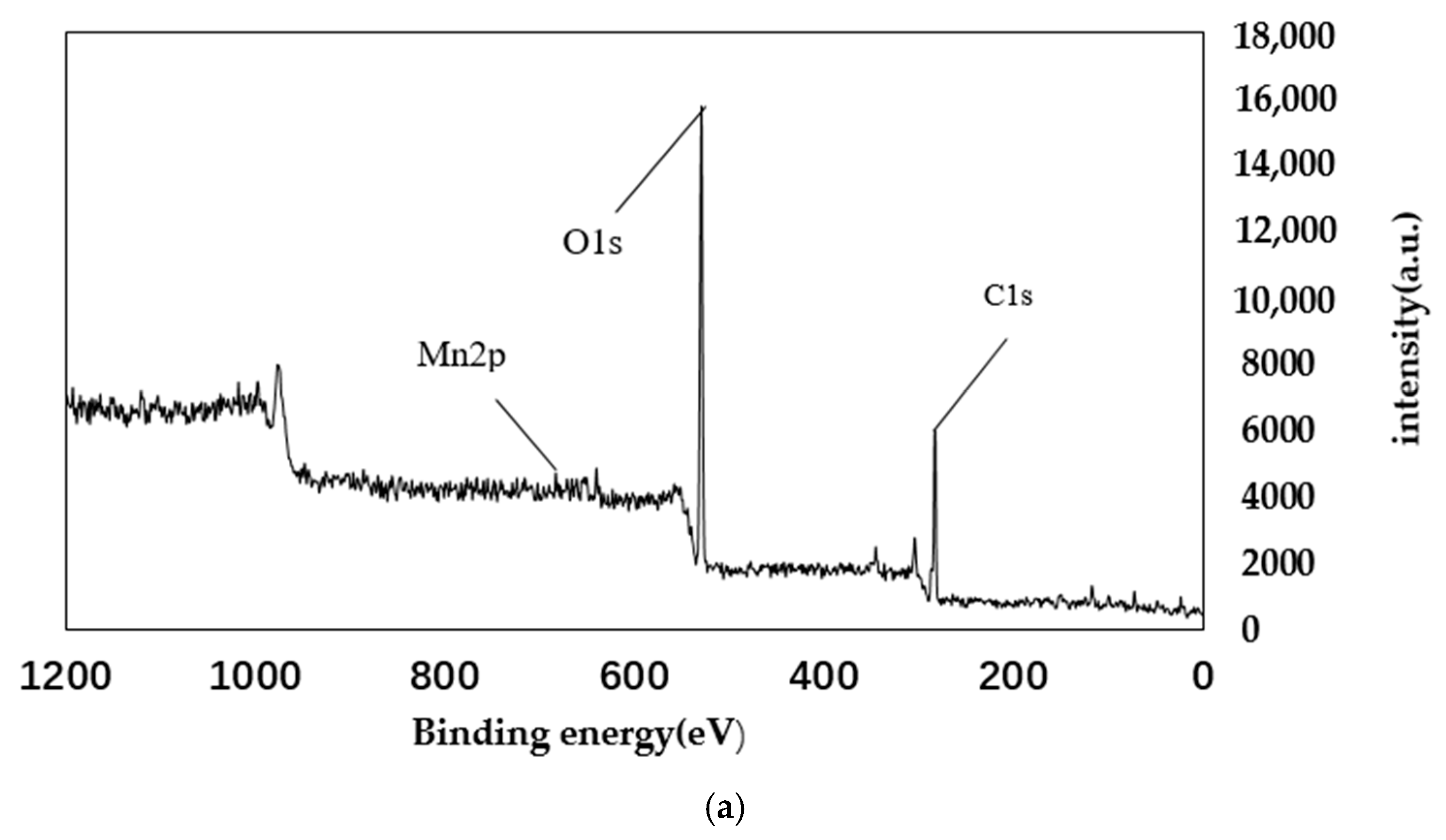
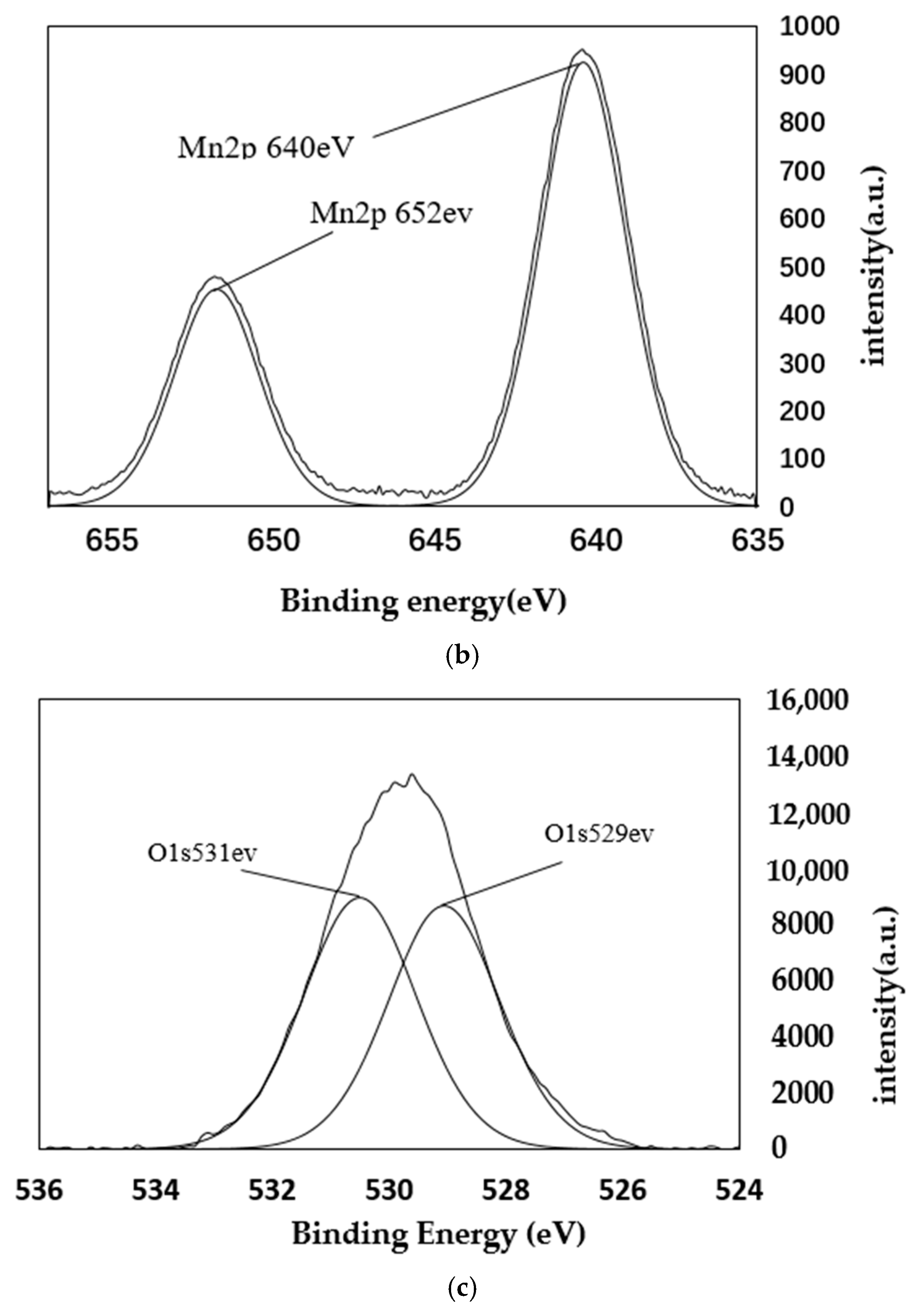
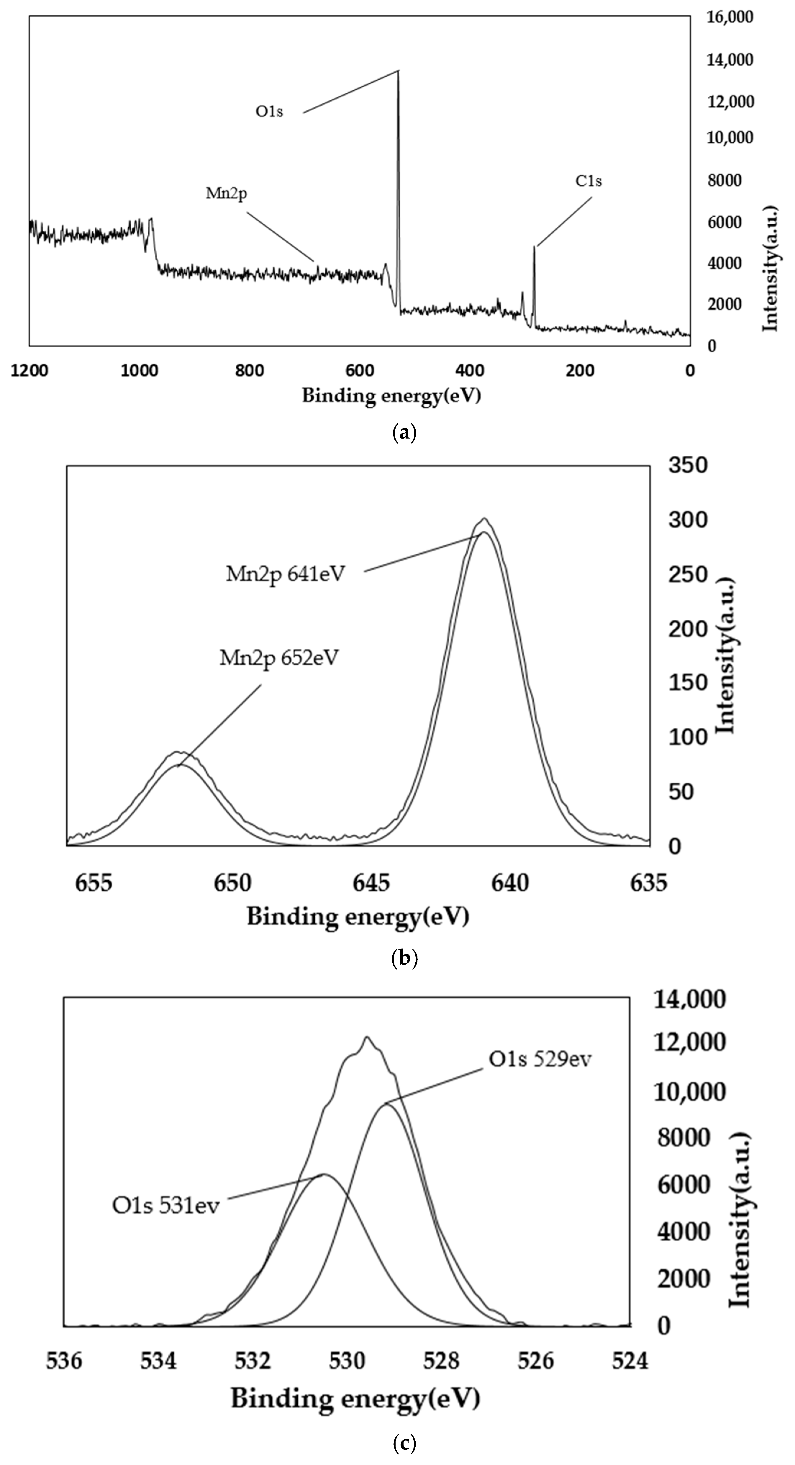
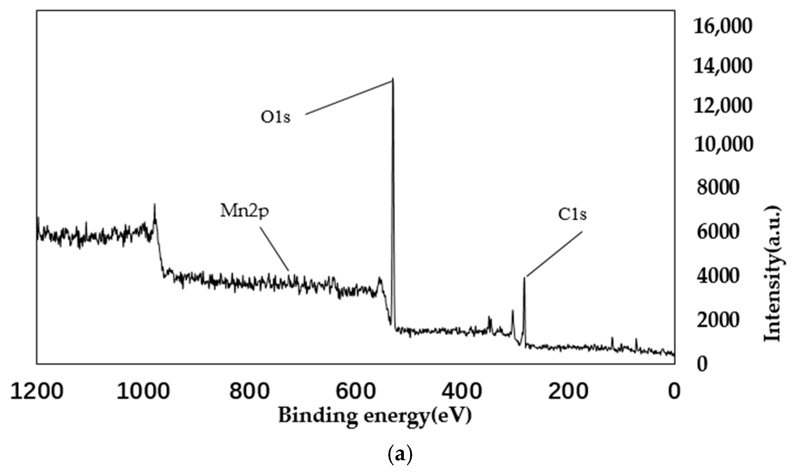
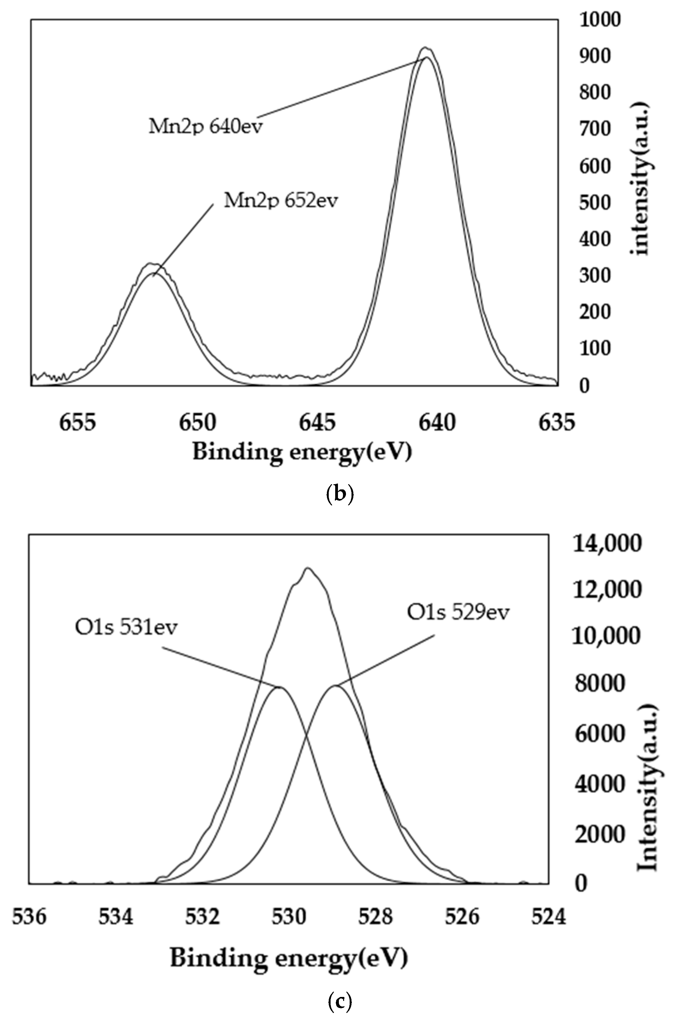
4.2. XPS Analysis
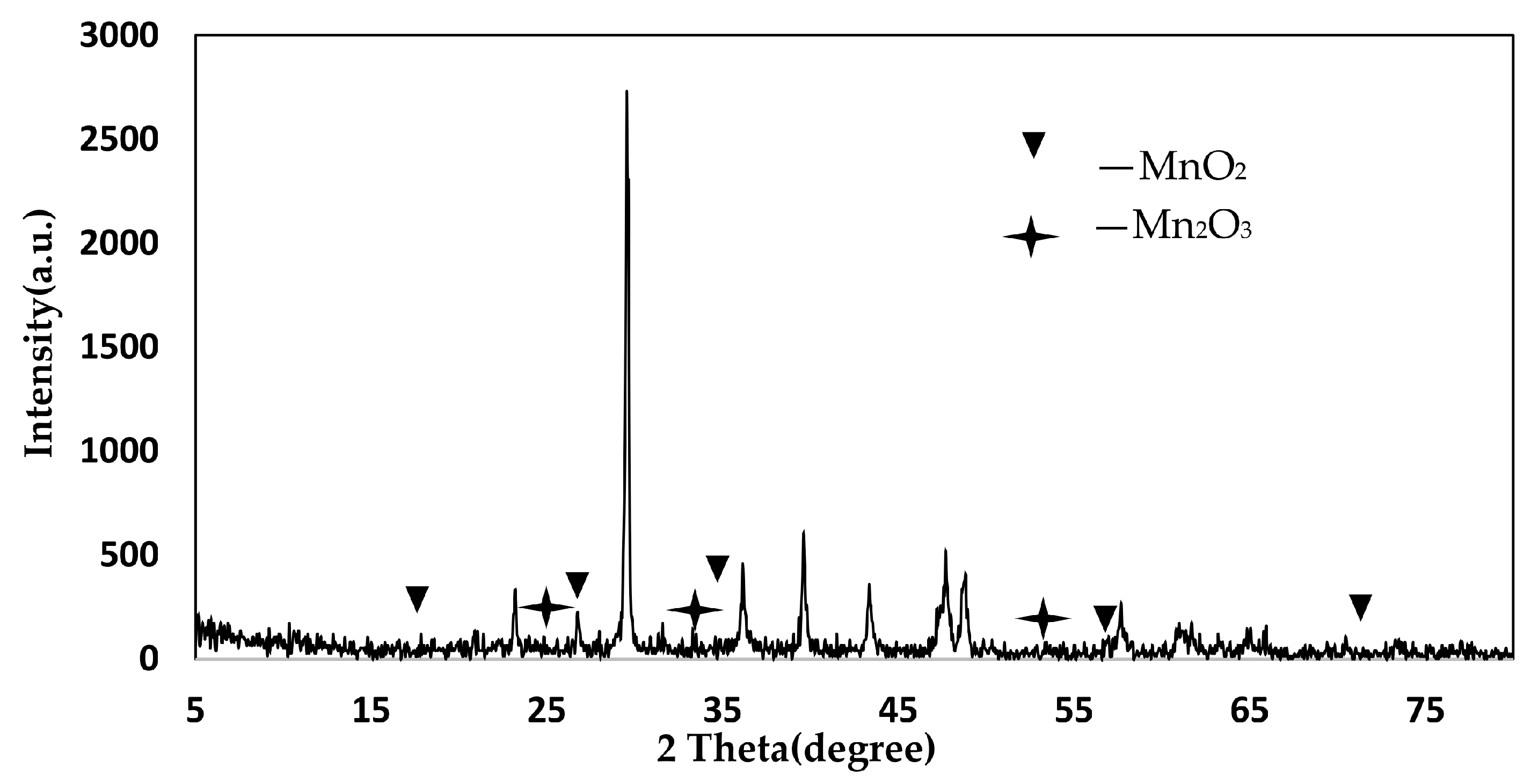
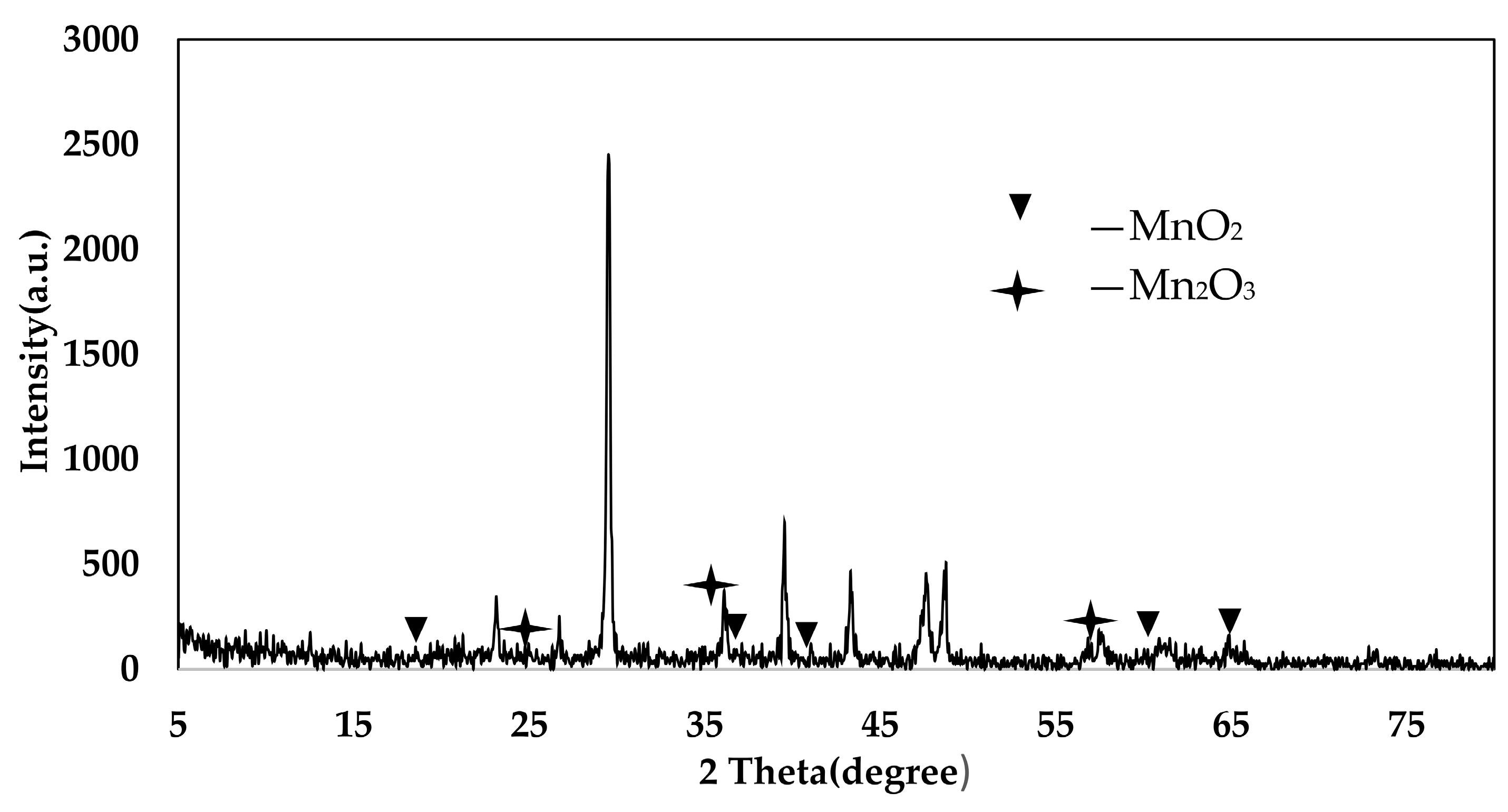
4.3. XRD Analysis
4.4. XRD Analysis
4.5. Elemental Analysis
5. Conclusions
- Catalysts activated with LiOH at a concentration of 15% have better denitration effects.
- Catalysts activated with LIOH for 4 h have better denitration effects.
- The sludge denitration catalyst (AP catalyst) prepared by plasma after being activated first, has a better denitration effect.
Author Contributions
Funding
Conflicts of Interest
References
- Wang, S.X.; Guo, R.T.; Pan, W.G.; Li, M.Y.; Sun, P.; Liu, S.M.; Liu, S.W.; Sun, X.; Liu, J. The deactivation mechanism of Pb on the Ce/TiO2 catalyst for the selective catalytic reduction of NOx with NH3: TPD and DRIFT studies. Phys. Chem. Chem. Phys. 2017, 19, 5333–5342. [Google Scholar] [CrossRef] [PubMed]
- Zhou, Y.; Li, C.T.; Fan, C.Z.; Fu, M.F.; Tao, L.; Yu, M.G.; Zhang, M.Y. Wet removal of sulfur dioxide and nitrogen oxides from simulated flue gas by Ca(ClO)2 solution. Environ. Prog. Sustain. 2016, 34, 1586–1595. [Google Scholar] [CrossRef]
- Li, P.X.; Zhang, R.D.; Liu, N.; Royer, S. Efficiency of Cu and Pd substitutionin Fe-based perovskites to promote N2 formation during NH3 selective catalytic oxidation(NH3-SCO). Appl. Catal. B-Environ. 2017, 203, 174–188. [Google Scholar] [CrossRef]
- Guo, R.T.; Wang, S.X.; Pan, W.G.; Li, M.Y.; Sun, P.; Liu, S.M.; Sun, X.; Liu, S.W.; Liu, J. Different poisoning effects of K and Mg on the Mn/TiO2 catalyst for selective catalytic reduction of NOX with NH3: A mechanistic study. J. Phys. Chem. C 2017, 121, 7881–7891. [Google Scholar] [CrossRef]
- Zhao, N.; Li, S.; Wang, J. Synthesis and application of different phthalocyanine molecular sieve catalyst for oxidative desulfurization. J. Solid State Chem. 2015, 225, 347–353. [Google Scholar] [CrossRef]
- Hu, Y.; Griffiths, K. Selective catalytic reduction of NO in the presence of SO2 and O2: The poisoning effect of SOx under oxygen rich and lean conditions. Surf. Sci. 2017. [Google Scholar] [CrossRef]
- Zeng, X.; Liu, J.; Zhao, J. Catalytic wet oxidation of pharmaceutical sludge by molecular sieve loaded with Cu/Ce. Catalysts 2018, 8, 67. [Google Scholar] [CrossRef]
- Zhang, R.; Wang, C.; Li, K.; Sun, X.; Ning, P.; Tang, L.H.; Liu, Y. Influence of Ca doping and calcination temperature on selective catalytic oxidation of NO over Mn-Ca-Ox-(CO3)y catalyst. New J. Chem. 2017, 41. [Google Scholar] [CrossRef]
- Ramis, G.; Yi, L.; Busca, G. Ammonia activation over catalysts for the selective catalytic reduction of NOx, and the selective catalytic oxidation of NH3. An FT-IR study. Catal. Today 1996, 28, 373–380. [Google Scholar] [CrossRef]
- Zhang, X.Y.; Wang, H.; Wang, Z.; Qu, Z.P. Adsorption and surface reaction pathway of NH3, selective catalytic oxidation over different Cu-Ce-Zr catalysts. Appl. Surf. Sci. 2018. [Google Scholar] [CrossRef]
- Wang, F.; Ma, J.Z.; He, G.Z.; Chen, M.; Zhang, C.B.; He, H. Nanosize effect of Al2O3 in Ag/Al2O3 catalyst for the selective catalytic oxidation of ammonia. ACS Catal. 2018, 8. [Google Scholar] [CrossRef]
- Zhou, G.Q.; Fang, F.; Chen, Z.W.; He, Y.F.; Sun, H.L.; Shi, H.X. Facile synthesis of paper mill sludgederived heterogeneous catalyst for the Fenton-like degradation of methylene blue. Catal. Commun. 2015, 62, 71–74. [Google Scholar] [CrossRef]
- Lu, S.Y.; Liu, Y.Z.; Li, F.; Sun, Z.G.; Zhang, L.Q. Characterization of ferromagnetic sludge-based activated carbon and its application in catalytic ozonation of p-chlorobenzoic acid. Environ. Sci. Pollut. Res. 2018, 25, 1–9. [Google Scholar] [CrossRef] [PubMed]
- Guo, S.; Yuan, N.; Zhang, G.; Yu, J.C. Graphene modified iron sludge derived from homogeneous Fenton process as an efficient heterogeneous Fenton catalyst for degradation of organic pollutants. Microporous Mesoporous Mater. 2017, 238, 62–68. [Google Scholar] [CrossRef]
- Xie, Q.; Peng, P.; Liu, S.; Min, M.; Cheng, Y.; Wan, Y.; Li, Y.; Liu, X.; Liu, Y.; Chen, P.; et al. Fast microwave-assisted catalytic pyrolysis of sewage sludge for bio-oil production. Bioresour. Technol. 2014, 172, 162–168. [Google Scholar] [CrossRef] [PubMed]
- Hu, M.; Lan, G.; Chen, Z.; Ma, C.; Zhou, Y.; Chen, J.; Ma, S.; Laghari, M.; Xiao, B.; Zhang, B. Syngas production by catalytic in-situ steam co-gasification of wet sewage sludge and pine sawdust. Energy Convers. Manag. 2016, 111, 409–416. [Google Scholar] [CrossRef]
- Liu, J.J.; Diao, Z.H.; Liu, C.M.; Jiang, D.; Kong, L.J.; Xu, X.R. Synergistic reduction of copper (II) and oxidation of norfloxacin over a novel sewage sludge-derived char-based catalyst: Performance, fate and mechanism. J. Clean. Prod. 2018, 182, 794–804. [Google Scholar] [CrossRef]
- Su, C.; Li, W.; Chen, M.; Huang, Z.; Wu, L. Effect of iron-manganese-sepiolite as heterogeneous Fenton-like catalyst on the performance and microbial community of anaerobic granular sludge treatment system. Bioresour. Technol. 2016, 200, 1065–1072. [Google Scholar] [CrossRef] [PubMed]
- Faheem, M.; Jiang, X.; Wang, L.; Shen, J. Synthesis of Cu2O-CuFe2O4 microparticles from Fenton sludge and its application in the Fenton process: The key role of Cu2O in the catalytic degradation of phenol. RSC Adv 2018, 8, 5740–5748. [Google Scholar] [CrossRef]
- Chen, Q.L.; Guo, R.T.; Wang, Q.S.; Pan, W.G.; Wang, W.H.; Yang, N.Z.; Lu, C.Z.; Wang, S.X. The catalytic performance of Mn/TiWOx, catalyst for selective catalytic reduction of NOx, with NH3. Fuel 2016, 181, 852–858. [Google Scholar] [CrossRef]
- Wu, Z.; Jin, R.; Liu, Y.; Wang, H. Ceria modified MnOx/TiO2 as a superior catalyst for NO reduction with NH3 at low-temperature. Catal. Commun. 2008, 9, 2217–2220. [Google Scholar] [CrossRef]
- Qi, G.; Yang, R.T.; Chang, R. MnOx–CeO2, mixed oxides prepared by co-precipitation for selective catalytic reduction of NO with NH3, at low temperatures. Appl. Catal. B-Environ. 2004, 51, 93–106. [Google Scholar] [CrossRef]
- Li, S.; Huang, B.; Yu, C. A CeO2-MnOx, core-shell catalyst for low-temperature NH3-SCR of NO. Catal. Commun. 2017, 98, 47–51. [Google Scholar] [CrossRef]
- Zhang, J.; Zhang, J.; Xu, Y.; Su, H.; Li, X.; Zhou, J.; Qian, G.; Li, L.; Xu, Z. Efficient selective catalytic reduction of NO by novel carbon-doped metal catalysts made from electroplating sludge. Environ. Sci. Technol. 2014, 48, 11497. [Google Scholar] [CrossRef] [PubMed]
- Jogi, I.; Erme, K.; Levoll, E.; Raud, J.; Stamate, E. Plasma and catalyst for the oxidation of NOx. Plasma Sources Sci. Technol. 2018, 27. [Google Scholar] [CrossRef]
- Li, G.; Zhu, B.; Sun, Y.; Yin, S.; Zi, Z.; Fang, Q.; Ge, T.; Li, J. Study of the alkali metal poisoning resistance of a Co-modified Mn/Ni foam catalyst in low-temperature flue gas SCR DeNOx. J. Mater. Sci. 2018, 53, 9674–9689. [Google Scholar] [CrossRef]
- Lee, B.J.; Kang, H.C.; Jo, J.O.; Mok, Y.S. Consideration of the role of plasma in a plasma-coupled selective catalytic reduction of nitrogen oxides with a hydrocarbon reducing agent. Catalysts 2017, 7, 325. [Google Scholar] [CrossRef]
- Jiang, N.; Shang, K.F.; Lu, N.; Li, H.; Li, J.; Wu, Y. High-efficiency removal of NOx from flue gas by multitooth wheel-cylinder corona discharge plasma facilitated selective catalytic reduction process. IEEE Trans. Plasma Sci. 2016, 44, 2738–2744. [Google Scholar] [CrossRef]
- Zhang, L.; Sha, X.L.; Zhang, L. Synergistic catalytic removal NOX and the mechanism of plasma and hydrocarbon gas. AIP Adv. 2016, 6, 1–8. [Google Scholar] [CrossRef]
- Boningari, T.; Smirniotis, P.G. Impact of nitrogen oxides on the environment and human health: Mn-based materials for the NOx abatement. Curr. Opin. Chem. Eng. 2016, 13, 133–141. [Google Scholar] [CrossRef]
- Cao, F.; Xiang, J.; Su, S.; Wang, P.; Hu, S.; Sun, L. Ag modified Mn–Ce/γ-Al2O3, catalyst for selective catalytic reduction of NO with NH3, at low-temperature. Fuel Process. Technol. 2015, 135, 66–72. [Google Scholar] [CrossRef]
- O’Brien, C.J.; Droege, D.G.; Jiu, A.Y.; Gandhi, S.S.; Paras, N.A.; Olson, S.H.; Conrad, J. Photoredox cyanomethylation of indoles: Catalyst modification and mechanism. J. Org. Chem. 2018. [Google Scholar] [CrossRef] [PubMed]
- Wang, F.; Wang, S.; Meng, Y.; Zhang, L.; Wu, Q.; Hao, J. Mechanisms and roles of fly ash compositions on the adsorption and oxidation of mercury in flue gas from coal combustion. Fule 2016, 163, 232–239. [Google Scholar] [CrossRef]
- Chen, C.H.; Njagi, E.C.; Chen, S.Y.; Horvath, D.T.; Xu, L.; Morey, A.; Mackin, C.; Joesten, R.; Suib, S.L. Structural distortion of molybdenum-doped manganese oxide octahedral molecular sieves for enhanced catalytic performance. Inorg. Chem. 2015, 54, 10163–10171. [Google Scholar] [CrossRef] [PubMed]
- Chandrasekhar, S.; Kumar, C.P.; Kumar, T.P.; Haribabu, K.; Jagadeesh, B.; Lakshmi, J.K.; Mainkar, P.S. ChemInform abstract: Peptidomimetic organocatalysts: Efficient michael addition of ketones onto nitroolefins with very low catalyst loading. RSC Adv. 2015, 46, 30325–30331. [Google Scholar] [CrossRef]
- Jampaiah, D.; Ippolito, S.J.; Sabri, Y.M.; Tardio, J.; Selvakannan, P.R.; Nafady, A.; Reddy, N.M.; Bhargava, S.K. Ceria-zirconia modified MnOx catalysts for gaseous elemental mercury oxidation and adsorption. Catal. Sci. Technol. 2016, 6, 1792–1803. [Google Scholar] [CrossRef]
- Jampaiah, D.; Tur, K.M.; Venkataswamy, P.; Ippolito, S.J.; Sabri, J.M.; Tardio, J.; Bhargava, S.K.; Reddy, B.M. Catalytic oxidation and adsorption of elemental mercury over nanostructured CeO2–MnOx catalyst. RSC Adv. 2015, 5, 30331–30341. [Google Scholar] [CrossRef]
- Li, H.; Wu, C.Y.; Li, L.; Li, Y.; Zhao, Y.; Zhang, J. Kinetic modeling of mercury oxidation by chlorine over CeO2–TiO2, catalysts. Fuel 2013, 113, 726–732. [Google Scholar] [CrossRef]
- Li, H.; Wu, C.Y.; Li, Y.; Zhang, J. Superior activity of MnOx-CeO2/TiO2, catalyst for catalytic oxidation of elemental mercury at low flue gas temperatures. Appl. Catal. B-Environ. 2012, 111, 381–388. [Google Scholar] [CrossRef]
- Li, J.; Chen, J.; Yu, Y.; He, C. Fe–Mn–Ce/ceramic powder composite catalyst for highly volatile elemental mercury removal in simulated coal-fired flue gas. J. Ind. Eng. Chem. 2015, 25, 352–358. [Google Scholar] [CrossRef]


| Sample Mass | Nitrogen Content/% | Carbon Content/% | Hydrogen Content/% | C/N |
|---|---|---|---|---|
| 3.931 | 1.568 | 15.12 | 2.549 | 9.64 |
| >5 ppm | 1~5 ppm | 0.1~1 ppm | <0.1 ppm |
|---|---|---|---|
| Al Ca Mg Fe Na P S Si | B K Sr Ti Zn. | Ag Ba Mn Ni Pd | As Be Cd Ce Cr Cu and other 30 kinds |
| Sample Mass | Nitrogen Content/% | Carbon Content/% | Hydrogen Content/% | C/N | Manganese Content/% |
|---|---|---|---|---|---|
| 3.769 | 1.543 | 15.097 | 2.556 | 9.784 | 1.264 |
| Sample Mass | Nitrogen Content/% | Carbon Content/% | Hydrogen Content/% | C/N | Manganese Content/% |
|---|---|---|---|---|---|
| 3.761 | 1.559 | 15.063 | 2.511 | 9.661 | 1.271 |
© 2018 by the authors. Licensee MDPI, Basel, Switzerland. This article is an open access article distributed under the terms and conditions of the Creative Commons Attribution (CC BY) license (http://creativecommons.org/licenses/by/4.0/).
Share and Cite
Zhang, L.; Yang, C.; Zhang, L.; He, H.; Luo, M.; Jia, Y.; Li, Y. Application of Plasma Treatment in Preparation of Soybean Oil Factory Sludge Catalyst and Its Application in Selective Catalytic Oxidation (SCO) Denitration. Materials 2018, 11, 1609. https://doi.org/10.3390/ma11091609
Zhang L, Yang C, Zhang L, He H, Luo M, Jia Y, Li Y. Application of Plasma Treatment in Preparation of Soybean Oil Factory Sludge Catalyst and Its Application in Selective Catalytic Oxidation (SCO) Denitration. Materials. 2018; 11(9):1609. https://doi.org/10.3390/ma11091609
Chicago/Turabian StyleZhang, Lei, Chao Yang, Lei Zhang, Huibin He, Min Luo, Yang Jia, and Yonghui Li. 2018. "Application of Plasma Treatment in Preparation of Soybean Oil Factory Sludge Catalyst and Its Application in Selective Catalytic Oxidation (SCO) Denitration" Materials 11, no. 9: 1609. https://doi.org/10.3390/ma11091609
APA StyleZhang, L., Yang, C., Zhang, L., He, H., Luo, M., Jia, Y., & Li, Y. (2018). Application of Plasma Treatment in Preparation of Soybean Oil Factory Sludge Catalyst and Its Application in Selective Catalytic Oxidation (SCO) Denitration. Materials, 11(9), 1609. https://doi.org/10.3390/ma11091609