Article

A Study of the Effects of Hf and Sn on the Microstructure, Hardness and Oxidation of Nb-18Si Silicide Based Alloys without Ti Addition

by
Eleftherios Zacharis
,
Claire Utton
and
Panos Tsakiropoulos
*
Department of Materials Science and Engineering, Sir Robert Hadfield Building, University of Sheffield, Mappin Street, Sheffield S1 3JD, UK
*
Author to whom correspondence should be addressed.
Materials 2018, 11(12), 2447; https://doi.org/10.3390/ma11122447
Submission received: 19 October 2018 / Revised: 19 November 2018 / Accepted: 27 November 2018 / Published: 3 December 2018

Abstract

:
The paper presents the results of an experimental study of large (≈0.6 kg) arc melted buttons of four Ti free Nb-silicide based alloys with Sn addition with nominal compositions (at.%) Nb-18Si-5Hf-5Sn (EZ1), Nb-18Si-5Al-5Sn (EZ7), Nb-18Si-5Cr-5Hf-5Sn (EZ3) and Nb-18Si-5Al-5Hf-5Sn (EZ4). The alloys were studied in the as-cast and heat treated conditions. In all the alloys there was macrosegregation of Si (MACSi). Among the single element additions Hf had the weakest and Sn the strongest effect on MACSi. The simultaneous presence of Cr and Hf in the alloy EZ3 had the strongest effect on MACSi. In all the alloys the βNb5Si3 was the primary phase and was present after the heat treatment(s), the Nb3Si silicide was suppressed and the A15-Nb3Sn intermetallic was stable. The Nbss was not stable in the alloys EZ7 and EZ4 and the C14-NbCr2 Laves phase was stable in the alloy EZ3. Very Hf-rich Nb5Si3 was stable in the alloy EZ4 after prolonged heat treatments. Eutectics were observed in all the alloys. These were binary eutectics in the alloys EZ1 and EZ7, where respectively they consisted of the Nbss and βNb5Si3, and βNb5Si3 and A15-Nb3Sn phases. Most likely ternary eutectics consisting of the Nbss, C14-NbCr2 and βNb5Si3, and Nbss, βNb5Si3 and A15-Nb3Sn phases were observed, respectively in the alloys EZ3 and EZ4. The addition of Al increased the vol% of the Nb5Si3 and A15-Nb3Sn phases, particularly after the heat treatment(s). The lattice parameter of Nb respectively increased and decreased with the addition of Hf, and Al or Cr and the latter element had the stronger negative effect. Pest oxidation was not suppressed in the alloys of this study.

1. Introduction

Niobium silicide based alloys (or Nb-silicide in situ composites) currently are developed owing to their potential to replace Ni-based superalloys in future aero-engines to enable the latter to meet new environmental and performance targets. These new ultra-high temperature alloys must meet property goals for toughness, creep resistance and oxidation. The property goals were given in [1]. The aforementioned properties depend on the chemical composition, distribution (size and spatial) and volume fraction of the phases that are present in the microstructures of the alloys, where the most desirable ones are the bcc Nb solid solution (Nbss) for toughness, and the tetragonal Nb5Si3 silicide for creep resistance and oxidation. A high volume fraction of the Nbss has negative effect on the creep resistance and oxidation of the alloys. The volume fraction of Nb5Si3 is crucial for the toughness and creep of the alloys.
The progress made on the development of Nb-silicide based alloys until the start of the 21st century was reviewed by Bewlay and Jackson [1]. More recently the alloying behaviour of Nb-silicide based alloys and their key phases was studied in [2,3,4,5,6] where links between alloying and properties were discussed and the usefulness of these studies for the design and/or selection of new alloys was demonstrated in [6]. Also, it was shown that some of the studied Nb-silicide based alloys, and some of the bcc Nb solid solutions and Nbss + βNb5Si3 eutectics that are formed in Nb-silicide based alloys [7] satisfy the standard definition of the so-called High Entropy Alloys (HEAs) [6].
Nb-silicide based alloys can offer a balance of properties and at the same time satisfy some of the property goals. Hafnium, Sn and Ti are important additions in these alloys for achieving a balance of properties. Each of these three elements improves oxidation, particularly in the presence of Al and/or Cr [8,9,10,11]. Ti in synergy with Al and/or Cr cannot suppress pest oxidation [11] but Sn can when it is in synergy with these elements [9]. The concentrations of Hf and Ti are important for creep resistance [6,12]. Also, primary phase selection and phase stability in the alloys depends on the synergies of the aforementioned elements.
To date, most of the research on Nb-silicide based alloys with Hf and/or Sn additions is on Ti containing alloys. Ti and Hf behave similarly in these alloys. For example, both elements can stabilize the hexagonal γNb5Si3, their concentrations and those of Al and/or Cr in the Nbss are inter-dependent [6] and the partitioning of Ti and Hf in the microstructure can make the identification of phases very difficult, particularly when Sn is also present [11,13]. There is some limited research in Ti-free Nb-silicide based alloy where (i) Hf was in synergy (a) only with Si or (b) with Al and Si or (c) with Cr and Si and (ii) Sn was in synergy only with Si. Indeed, the Ti-free ternary alloys of nominal compositions Nb-18Si-5Sn (alloy NV9 in [14]), Nb-19Si-5Hf and Nb-16Si-xHf (x = 1, 3, 7) [15,16] and the Ti-free quaternary alloys of nominal compositions Nb-18Si-5Cr-5Hf and Nb-18Si-5Al-5Hf (respectively the alloys YG1 and YG2 in [17]) have been studied (in this paper all compositions are given in at.% unless otherwise stated).
In Nb-19Si the primary phase is Nb3Si [18]. The calculated solidification path for the alloy Nb-19Si-5Hf indicated the Nb(Hf)3Si silicide as the primary phase [15]. Increase of the Hf concentration in Nb-16Si-xHf (x =1, 3, 7) alloys refined the microstructure, decreased the volume fraction of the Nbss + Nb3Si eutectic and improved the fracture toughness of the alloys. The latter was attributed to the Hf addition promoting a transition of the Nbss fracture from brittle cleavage to plastic stretching [16]. When Al was added to the Nb-18Si-5Al-5Hf alloy (alloy YG2 in [17]), the Nb3Si was suppressed, the primary phase was the βNb5Si3 and the volume fraction of the Nbss was reduced. However, when Cr replaced Al in the Nb-18Si-5Cr-5Hf alloy (alloy YG1 in [17]) the primary phase was the βNb5Si3 but the Nb3Si formed in parts of the button that had not solidified under high cooling rate. The Nb3Si was not stable in the heat treated alloy YG1.
With the addition of Sn in the alloy Nb-18Si-5Sn the primary phase was the βNb5Si3 and the Nb3Si was suppressed, the Nbss + Nb3Si eutectic was replaced by the Nbss + βNb5Si3 eutectic and the A15-Nb3Sn phase was also stable in the microstructure [14] (see discussion and the Supplemental data). Tin partitioned to the bcc Nbss stronger than to the Nb5Si3 and did not significantly affect the solubility of Si in the Nbss [14]. In other words, the research has shown (i) that the suppression of the Nb3Si was promoted by the synergy (a) of Sn with Si, (b) of Al with Hf and Si and (c) of Hf with Si but not when Cr and Hf were in synergy with Si and (ii) that the primary phase was the βNb5Si3 in Nb-silicide based alloys where all the aforementioned elements (i.e., Al, Cr, Hf, Si, Ti) were in synergy. It should be noted that the alloys NV9, YG1 and YG2 were prepared as arc melted buttons of approximately 0.6 kg weight (see discussion). Recently it was shown that the βNb5Si3 to αNb5Si3 transformation in the alloys depends on the size of arc melted button [19].
How would the simultaneous presence of Hf and Sn with/out Al or Cr (i.e., of the elements that are key to improving the oxidation of Nb-silicide based alloys) affect the microstructure and properties of Ti-free Nb-silicide based alloys? Would the macrosegregation of Si increase or decrease? Would eutectics form in such alloys? Which would be the phases in the eutectics? Would the Nbss be stable in the alloys? Would the stability of βNb5Si3 be increased or decreased? What would be the effect on hardness? Would pest oxidation be suppressed? The motivation for the research presented in this paper was (i) to answer these questions, (ii) to show the strong effect of the partitioning of Hf and Sn in the microstructure in the absence of Ti and (iii) to highlight the implication of (ii) for phase identification.
The structure of the paper is as follows. First, the microstructures of the four studied alloys in the as cast and heat treated conditions are presented and then the results for their hardness, densities and isothermal oxidation at 800 °C. Macrosegregation and the cast and heat treated microstructures are discussed followed by the hardness and oxidation of the alloys. We have decided to present the results for each alloy separately because we used different heat treatment temperatures and times for different alloys to study the stability of the Nb solid solution and the type of Nb5Si3 in their microstructures and also in order to address (ii) and (iii) above.

2. Experimental

The alloys of nominal compositions Nb-18Si-5Hf-5Sn (alloy EZ1), Nb-18Si-5Al-5Sn (alloy EZ7), Nb-18Si-5Cr-5Hf-5Sn (alloy EZ3) and Nb-18Si-5Al-5Hf-5Sn (alloy EZ4) were selected for this study. The effect of Hf or Al on microstructure and properties was studied using the alloys EZ1 and EZ7 that were compared with the Nb-18Si-5Sn alloy (alloy NV9 in [14]). The simultaneous addition of Al and Hf reduced significantly the volume fraction of the Nbss in the alloy Nb-18Si-5Al-5Hf compared with the addition of Cr and Hf in the alloy Nb-18Si-5Cr-5Hf (respectively the alloys YG2 and YG1 in [17]). The alloy EZ7 was selected to find out how Al and Sn affect the stability of the Nbss when present simultaneously in the alloy without Hf. The effect of Sn with Cr and Hf, or Al and Hf on microstructure and properties was studied in the alloys EZ3 and EZ4.
Large buttons of the aforementioned alloys of approximately 0.6 kg weight were prepared from elemental charges of purity better than 99.99 wt.% using arc melting with a non-consumable tungsten electrode and water cooled copper crucible in an argon atmosphere. Cubic specimens from the bulk of the ingot of each alloy were used for heat treatments at 1200 or 1500 °C and up to 300 h depending on alloy and for isothermal oxidation experiments. For the heat treatments cubic (2 × 2 × 2 cm3) specimens wrapped in Ta foil were placed in a LENTON 1850 high temperature tube furnace under a constant flow of Ti gettered argon (10−5 m3·s−1). The oxidation experiments were done at 800 °C in static air for up to 100 h using cubic (3 × 3 × 3 mm3) specimens of the heat treated alloys in a Stanton-Redcroft automatic thermo-recording balance.
The microstructures were characterized using X-ray diffraction (XRD) and electron probe micro-analysis (EPMA). For the XRD a Siemens D5000 diffractometer with Cu radiation was used and X-rays were collected with a step of 0.02 degrees over 2θ range 20 to 90 degrees. Peaks in the XRD diffractograms were identified by correlating data from the experiments with that from the JCPDS data (International centre for diffraction data). The lattice parameter of the Nbss was determined using the Nelson-Riley function [20]. Secondary electron (SE) and backscatter electron (BSE) imaging and quantitative analysis were undertaken using a JEOL 8600 EPMA equipped with energy-dispersive (EDS) and wavelength-dispersive (WDS) spectrometers. Standards of high purity elements of Nb, Si, Cr, Al, Hf and Sn, which had been polished to a finish of 1 μm, were used. The operational software was the Oxford Link INCA software with the XPP corrections method which is based on the Rhi-Rho-Z approach. At least 10 analyses for each phase or area of the ingot were performed. The chemical analysis data is given in the Tables S1–S4 in the Supplemental data. In these Tables the data is for the phases in the whole of each cast button and the average value, standard deviation and the minimum and maximum analyses values are given. The data in the Tables S1–S4 is for the phases that were identified both by XRD and EPMA.
The Vickers hardness (HV) of all the alloys in the as cast and the heat treated conditions was measured using a CV-430 AAT automatic hardness testing machine. The load used was 10 kg and was applied for 20 s. At least 10 measurements were taken for each alloy. The hardness of phases in the alloys were measured using a Mitutoyo micro-hardness testing machine. The load used was 0.1 kg and was applied for 20 s. At least 10 measurements were taken for each phase.
A Sartorius Masterpro Series electronic analytical balance along with a Sartorius YDK density determination kit was used to calculate the density of the alloys. The Archimedean principle was applied for measuring the density of the alloys.

3. Results

The actual compositions of the alloys EZ1, EZ7, EZ3 and EZ4 respectively were 70Nb-20.5Si-5.4Hf-4.1Sn, 72.1Nb-18.9Si-5Al-4Sn, 66.2Nb-19.7Si-4.5Cr-5.3Hf-4.5Sn and 67.6Nb-19.4Si-4.4Al-5.3Hf-3.3Sn (see Tables S1–S4 in the Supplemental data). Compared with their nominal compositions, the cast alloys were poorer in Sn and richer in Si. There was macrosegregation of Si (MACSi = CSimax − CSimin, where CSimax and CSimin respectively are the maximum and minimum measured concentrations in the cast button [21]) in all alloys and macrosegregation of Cr in the alloy EZ3. The values of MACSi were 2.8, 2.5, 4.1 and 3.9 at.% respectively for the alloys EZ1, EZ7, EZ3 and EZ4. The phases in the microstructures of the alloys are summarized in the Table 1. The Nb3Sn and Nb5Si3 were stable in all alloys.
As-cast alloy EZ1 (EZ1-AC): According to the XRD data the phases in the cast microstructure were the Nbss, αNb5Si3, βNb5Si3, Nb3Sn and HfO2 (Figure 1a). More peaks corresponded only to αNb5Si3 than only to βNb5Si3. The cast microstructure is shown in Figure 2a,b. The Nbss and Nb3Sn exhibited essentially the same contrast under BSE imaging, meaning these phases could be distinguished only by performing chemical analysis. The Si concentration in the Nbss was in agreement with data for Nb-silicide based alloys (e.g., [11,17]). The presence of Nb3Sn was confirmed by EPMA analyses only in the bulk of the ingot (Figure 2b). There were Hf-rich areas in the Nbss, Nb5Si3 and Nb3Sn. The Sn concentration in these Hf rich phases increased with their Hf concentration, and in the Hf rich Nb3Sn the Si concentration was reduced. The Hf rich areas exhibited a brighter contrast under BSE imaging (Figure 2a,b). The volume fraction of the Nb5Si3 was higher than those of the Nb3Sn and Nbss, which were the same (see Table A1 in the Appendix A).
A fine lamellar microstructure the compositions of which were essentially the same in the top, bulk and bottom of the button surrounded the Nb5Si3 (Figure 2a,b). In the bulk it was not possible to confirm whether the lamellar microstructure was binary consisting of the Nbss and Nb5Si3 phases, as it was in the top and bottom of the button, or ternary consisting of the Nbss, Nb5Si3 and Nb3Sn phases. Also, in the lamellar microstructure it was not possible to confirm whether some or all of the phases in it were Hf-rich because of the scale of the lamellae and the contrast of phases. The reason why in Table S1 in the Supplemental data the analysis of the lamellar microstructure in EZ1-AC is given for eutectic with Nbss and Nb5Si3 will become clear in the discussion.
Heat-Treated alloy EZ1-HT1 (1500 °C/100 h): The XRD data indicated that the microstructure consisted of Nbss, Nb3Sn, αNb5Si3 and βNb5Si3 and HfO2 (Figure 1a). There was still chemical inhomogeneity of Si, the concentration of which varied between 19.8 and 24 at.%, and Hf rich areas in Nb5Si3 (Table S1 in the Supplemental data). The average composition of HfO2 was 1.8Nb-2.5Si-32.5Hf-63.2O (at.%). The microstructure had coarsened and the lamellar microstructure that was evident throughout the cast button had not disappeared completely (Figure 2c). The average composition of the remnants of the lamellar microstructure was richer in Hf and Si and poorer in Sn (Table S1 in the Supplemental data).
Heat-Treated alloy EZ1-HT2 (1500 °C/200 h): The alloy was given a second heat treatment for an additional 100 h in order to further homogenize its microstructure and find out whether the βNb5Si3 and the Nbss would be stable. The EPMA data for EZ1-HT2 is given in Table S1 in the Supplemental data and the XRD data in Figure 1a. The chemical inhomogeneity of Si was reduced compared with EZ1-HT1. The microstructure was similar to that in EZ1-HT1, and consisted of the same phases (Figure 1a) with Hf rich areas still present in Nb5Si3. The XRD indicated that the βNb5Si3 silicide and the Nbss were present. There were no significant changes in the composition of the phases, with the exception of the Si concentration in the Nbss that was further reduced. Areas of prior eutectic microstructure were still present, but with reduced Sn and increased Si concentration compared with EZ1-AC. Thus, the lamellar microstructure that was observed in the cast alloy EZ1 was thermally stable after 200 h at 1500 °C. After this heat treatment, the volume fraction of the Nb5Si3 was half that in the cast alloy and the volume fraction of Nb3Sn was reduced slightly (see Table A1 in the Appendix A). The volume fraction of the prior eutectic microstructure was about 0.58, the same as in EZ1-HT1.
As-cast alloy EZ7 (EZ7-AC): Typical microstructures in different areas of the button are shown in Figure 3a,b and the phases are summarized in Table 1. The phases were the αNb5Si3, βNb5Si3 and Nb3Sn (Figure 1b). Approximately the same number of peaks corresponded only to βNb5Si3 and only to αNb5Si3. Sn-rich Nb3Sn was also observed. The latter exhibited a brighter contrast under BSE imaging compared with the “normal” Nb3Sn. The aforementioned phases were observed in all parts of the button, the microstructure of which was coarser in the bulk and finer in the bottom. In the latter, the microstructure consisted of Nb5Si3 and Sn-rich Nb3Sn. In all parts of the button there was also an Nb5Si3 + Sn-rich Nb3Sn lamellar microstructure (indicated as eutectic in the Table S2 in the Supplemental data, see discussion) that had formed adjacent to the primary Nb5Si3 dendrites. The average composition of this lamellar microstructure was the same in the top, bulk and bottom of the button (75.5Nb-13.4Si-5.4Al-5.7Sn). No solid solution was observed by XRD and EPMA. The volume fractions of the Nb5Si3 and Nb3Sn were essentially the same (see Table A1 in the Appendix A).
Heat-Treated alloy EZ7 (1500 °C/100 h): After the heat treatment the microstructure had coarsened (Figure 3c) and consisted of αNb5Si3, βNb5Si3 and Nb3Sn (Table S2 in the Supplemental data and Figure 1b). There was still large scale chemical inhomogeneity of Si, the concentration of which varied between 16 and 19.3 at.% (Table S2 in the Supplemental data). There were no Sn-rich areas present in the Nb3Sn in which the Si concentration was reduced compared with the cast alloy. There was no change of the volume fraction of each phase compared with the cast alloy (see Table A1 in the Appendix A). Remnants of coarsened prior eutectic areas were observed.
As-cast alloy EZ3 (EZ3-AC): According to the XRD data (Figure 4a) the Nbss, Nb3Sn, αNb5Si3, βNb5Si3, HfO2 and C14-NbCr2 Laves phase were present in the microstructure. Twice as many peaks corresponded only to αNb5Si3 compared with βNb5Si3. The microstructure of the alloy is shown in Figure 5. Identification of individual phases was not always possible using BSE imaging owing to the partitioning of Hf. The parts b and c in Figure 5 are given to help the reader identify the different phases in the cast alloy. A very fine lamellar microstructure that contained the NbCr2 Laves phase was formed next to, or around the Nb3Sn, usually in the regions between the Nb3Sn and the Hf-rich Nb5Si3 (Figure 5b,c) but also between the Nbss and Hf rich Nb5Si3. Analysis of the composition of the Laves phase by EPMA was not possible owing to its size. The composition of the lamellar microstructure (indicated as eutectic in the Table S3 in the Supplemental data, see discussion) was the average composition of the lamellar microstructure throughout the ingot. HfO2 particles were observed either inside or next to the lamellar microstructure. The volume fraction of the Nb5Si3 was slightly lower than the sum of the volume fractions of the Nb3Sn and Nbss (see Table A1 in the Appendix A).
Heat-treated alloy EZ3 (1200 °C /100 h): After this heat treatment there was still large scale chemical inhomogeneity for Si and Hf-rich areas persisted in the Nb5Si3 silicide (Table S3 in the Supplemental data). The microstructure is shown in Figure 6. Hafnia particles were mainly observed in the areas that were rich in Hf in the cast alloy. The microstructure consisted of large Nb5Si3 grains surrounded by a network of unevenly distributed Hf-rich Nb5Si3 with Nbss. Submicron particles of HfO2 were dispersed throughout these regions (Figure 6). The Nb3Sn was found adjacent to these areas and the Laves phase was found next to it. The Nbss was poorer in Cr, Si and Sn compared with EZ3-AC.
The XRD data indicated the presence of Nbss, Nb3Sn, αNb5Si3, βNb5Si3, HfO2 and C14 NbCr2 Laves phase (Figure 4a). Approximately twice as many peaks corresponded only to αNb5Si3 compared with βNb5Si3. The solid solution was stable in the microstructure, the volume fraction of Nb3Sn was more than double that in the cast alloy and the volume fraction of the Nb5Si3 was reduced slightly (Table A1 in the Appendix A). The volume fraction of the NbCr2 Laves phase was very low. The Cr rich areas in the microstructure can be seen in the Cr map in Figure 6. The prior lamellar microstructure areas had Cr + Si + Sn = 51.0 at.%, very close to the composition of the eutectic in the binary Nb-Cr phase diagram [22]. The volume fraction of the lamellar microstructure was about 0.24. The average composition of the Laves phase gave (Cr + Si + Sn) = 59.4 at.%, but there were some analyses that gave (Cr + Si + Sn) ≈ 64 at.%.
As-cast alloy EZ4 (EZ4-AC): Typical images of the microstructure of the cast alloy are shown in Figure 7. The XRD data indicated the presence of Nbss, αNb5Si3, βNb5Si3, γNb5Si3, HfO2 and Nb3Sn (Figure 4b). More peaks corresponded only to αNb5Si3 than only to βNb5Si3, as was the case for EZ1-AC. One very weak peak corresponded only to the γNb5Si3. The Nbss was observed only in the bulk and top of the ingot where it was formed next to the Nb3Sn and its volume fraction was significantly lower than those of the Nb5Si3 and Nb3Sn (see Table A1 in the Appendix A). Fine HfO2 particles were observed in all parts of the button. Hafnium rich areas were observed in the Nb5Si3 silicide and some Nbss grains (Figure 7a,c). A very fine lamellar microstructure formed adjacent to the Nb3Sn phase (Figure 7). It was not possible to confirm if the former was binary Nbss and Nb5Si3 or ternary Nbss, Nb5Si3 and Nb3Sn lamellar microstructure or whether some or all of the phases in it were Hf-rich, because of the scale of the lamellae and the contrast of phases. It is for this reason that in the Table S4 in the Supplemental data the analysis data of these areas is given for eutectic with Nbss and Nb5Si3, see discussion.
Heat-treated alloy EZ4-HT1 (1500 °C/100 h): There was no large scale chemical inhomogeneity of Si after this heat treatment. The microstructure consisted of a network of intersecting Nb5Si3 and Hf-rich Nb5Si3 dendrites surrounded by Nb3Sn (Figure 8a). The Nb3Sn was poorer in Si and richer in Al compared with the cast alloy (Table S4 in the Supplemental data). Submicron Nb3Sn particles formed in the Nb5Si3 silicide (Figure 8a). The exact composition of these particles could not be analyzed and their identity was deduced from their imaging under BSE imaging conditions. HfO2 particles were observed close to the Hf-rich Nb5Si3 silicide. The XRD (Figure 4b) indicated the presence of Nbss, αNb5Si3, βNb5Si3, γNb5Si3, HfO2 and Nb3Sn. The number of peaks that corresponded only to the γNb5Si3 had increased and there was no change of the number of peaks that corresponded to αNb5Si3 and βNb5Si3. Exhaustive study of the microstructure using EPMA did not confirm the existence of Nbss in EZ4-HT1. The volume fraction of the Nb5Si3 had increased compared with the cast alloy (see Table A1 in the Appendix A).
Heat-treated alloy EZ4-HT2 (1500 °C/200 h): The alloy EZ4 was heat treated for an additional 100 h at 1500 °C to confirm the stability or not of the Nbss and of the βNb5Si3 and γNb5Si3. The same specimen that was initially heat treated for 100 h at 1500 °C (i.e., specimen EZ4-HT1) was given another 100 h at 1500 °C (and subsequently this specimen was given another 100 h heat treatment at 1500 °C (total 300 h—EZ4-HT3, see below). The XRD (Figure 4b) indicated the presence of Nbss, αNb5Si3, βNb5Si3, γNb5Si3, HfO2 and Nb3Sn. The number of peaks that corresponded only to αNb5Si3, βNb5Si3 and γNb5Si3 had not changed. Thorough study of the microstructure of EZ4-HT2 using EPMA found only two areas with composition corresponding to Nbss and confirmed that a very low volume fraction of the solid solution was present in EZ4-HT2.
The typical microstructure is shown in Figure 8b. There were Hf-rich areas in Nb5Si3, and very Hf-rich Nb5Si3 was observed for the first time. In the latter the concentration of Hf was more than double that in the Hf-rich areas in Nb5Si3 (Table S4 in the Supplemental data). In this phase the Si + Sn + Al concentration was about 39.3 at.% with the Hf and Al concentration about 19.5 at.% and 5.4 at.%, respectively. The very Hf-rich Nb5Si3 phase was surrounded by two phase regions consisting of the Nbss and Hf-rich Nb5Si3. The submicron particles that were observed in the Nb5Si3 silicide after the first heat treatment at 1500 °C (EZ4-HT1) were almost non-existent after 200 h of heat treatment. The Nb3Sn was poorer in Si and richer in Al compared with EZ4-AC.
Despite the fact that the compositions of Nb3Sn, Nb5Si3 and Hf-rich Nb5Si3 in EZ4-HT1 and EZ4-HT2 were similar (Table S4 in the Supplemental data) the microstructure of EZ4-HT2 was significantly altered. There was a change in the volume fraction of the phases; that of Nb3Sn had increased to about 0.605 and that of Nb5Si3 had decreased to about 0.395 (see Table A1 in the Appendix A). Remnants of the prior eutectic were not observed.
Heat-treated alloy EZ4-HT3 (1500 °C/300 h): The microstructure of EZ4-HT3 was essentially the same as that of EZ4-HT2. The XRD (Figure 4b) indicated the presence of Nbss, αNb5Si3, βNb5Si3, γNb5Si3, HfO2 and Nb3Sn. The number of peaks that corresponded only to αNb5Si3, βNb5Si3 and γNb5Si3 had not changed compared with EZ4-HT2. Thorough examination of the microstructure using EPMA did not find any evidence for the solid solution. It was concluded that if there was solid solution present in EZ4-HT3, its volume fraction would be extremely low.
Data for the chemical composition of the phases is given in Table S4 in the Supplemental data and the typical microstructure is shown in Figure 8c. The EPMA data confirmed that the microstructure consisted of Nb3Sn, Nb5Si3, Hf-rich Nb5Si3, very Hf-rich Nb5Si3 and HfO2. As was the case in EZ4-HT2, the submicron Nb3Sn particles that had been observed in the Nb5Si3 silicide in EZ4-HT1 were no longer present in EZ4-HT3. The HfO2 particles were much more abundant and coarser especially in the regions that were closer to the edges of the specimen. The volume fraction of the phases was the same as that in EZ4-HT2 (see Table A1 in the Appendix A).

3.1. Density, Hardness and Lattice Parameter of Nbss

Data for the density, hardness and % area of phases for the as-cast and heat treated alloys is summarized in the Table A1 in the Appendix A, and data for the lattice parameter of the Nb solid solution is given in the Table A2 in the Appendix A. The latter includes data for the alloy Nb-18Si-5Sn (alloy NV9 in [14]). The lattice parameter of the Nbss was lower than that of pure Nb (3.3007 Å) with the exception of the solid solution in the heat treated alloy EZ1, and increased after heat treatment (see Table A2 in the Appendix A).
The data in Table A1 in the Appendix A shows (a) that the density of all alloys was less than 8.4 g/cm3 and that the alloy EZ7 had the lowest density, (b) that the hardness of the alloys in the heat treated condition was lower than in the as-cast condition with the exception of the alloy EZ7 and (c) that the volume fraction of the Nb3Sn phase was high in the alloys that contained Al. The solid solution was not stable in the alloy EZ7 and (it is highly likely that it was not stable) in the alloy EZ4.
The hardness of the Nb5Si3 in the alloys was lower than that of unalloyed Nb5Si3 (1360 HV [14]) with the exception of the cast alloy EZ1 where it was essentially the same, and the hardness of the alloyed Nb3Sn was significantly higher than that of the unalloyed Nb3Sn (450 HV [14]).

3.2. Oxidation

All the alloys exhibited pest oxidation. The alloys EZ4 and EZ7 oxidized very rapidly and in less than 100 h had gained weights in excess of the weight measurement capability of the instrument used for the experiments. The specimen of the alloy EZ4 was converted into powders, and that of the alloy EZ7 broke into many small angular pieces. The specimen of the alloy EZ1 oxidized following linear oxidation kinetic with kl = 9 × 10⁻⁷ g·cm−2·s−1 and after 100 h was converted into powders. The specimen of the alloy EZ3 also followed linear kinetics with kl = 8.5 × 10⁻⁷ g·cm−2·s−1 and after 100 h formed powder and a smaller cubic solid core.

4. Discussion

4.1. Macrosegregation of Si

Macrosegregation is common in alloys that are prepared using arc melting with water cooled crucibles and has been reported in many Nb-silicide based alloys [21]. There was macrosegregation of Si (MACSi) in all the alloys and the chemical inhomogeneity of Si persisted in the heat treated microstructures of the alloys with the exception of the alloy EZ4. The effects of specific element additions individually and simultaneously on the macrosegregation of Si after casting were separated by comparing the data for different alloys. Figure 9 summarizes the effects of Al, Cr, Hf and Sn individually and Al + Hf and Cr + Hf simultaneously on the macrosegregation of Si after casting. Figure 9 shows that among the single element additions Hf had the weakest and Sn the strongest effect on MACSi, and that the synergy of Cr and Hf had the strongest effect on MACSi.
The effect of the alloying additions of Al, Cr, Hf and Sn on the macrosegregation of Si in the alloys EZ1, EZ7, EZ3 and EZ4 also was studied using the parameters discussed in [21]. Table 2 shows that different parameters controlled MACSi when Hf and Sn were in synergy with Al or Cr. In the former case the increase of MACSi was associated with the increase of the parameters Tmsp, ΔHmsp, ΔHmalloy/Tmalloy and in the latter with a decrease of the parameters Tmalloy, ΔHmalloy, ΔHmsd and Tmsd, in agreement with [21].

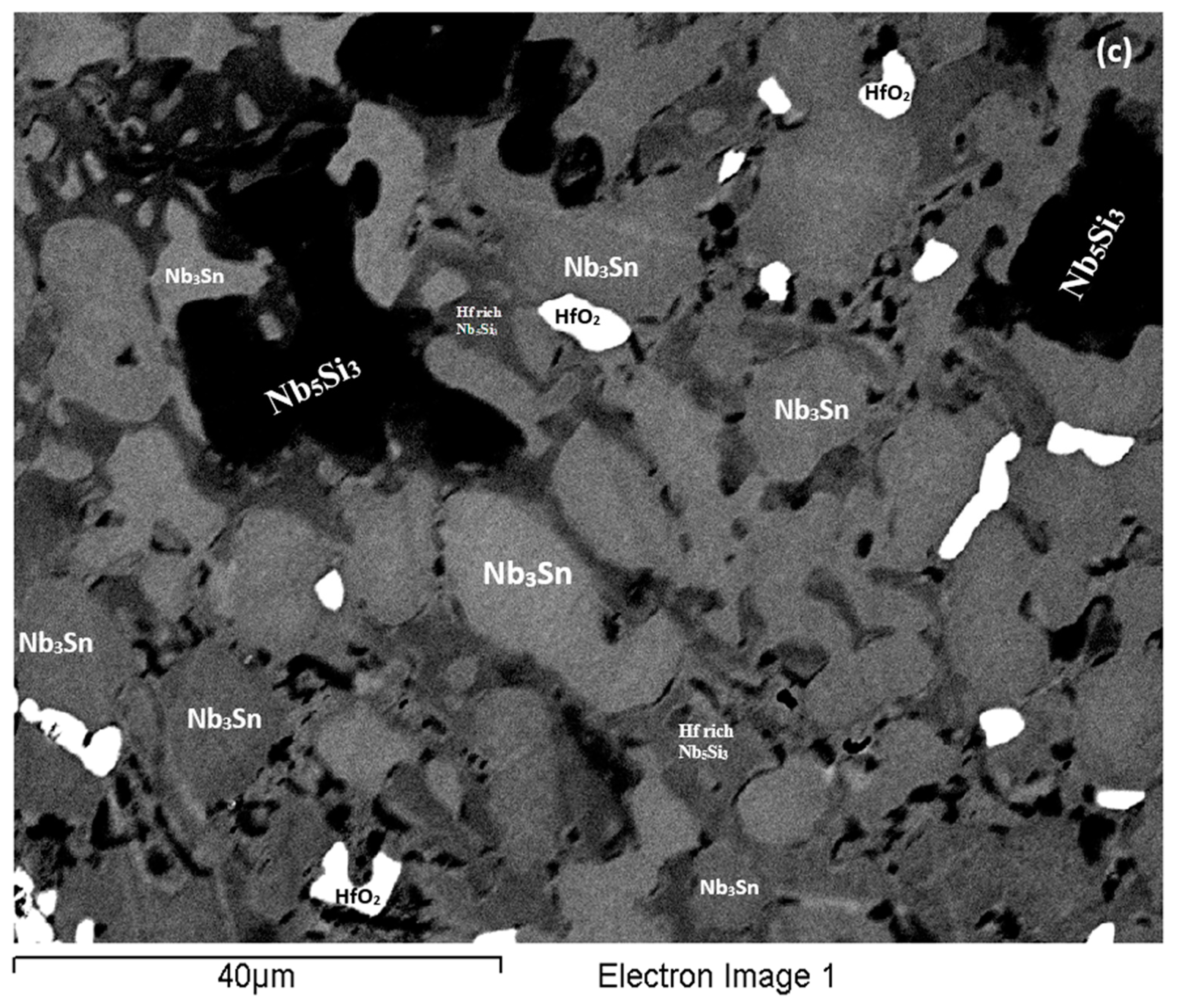
4.2. Microstructures

4.2.1. Primary Phase

In all the as-cast buttons of the alloys of this study the Nb5Si3 was the primary phase. The XRD data (Figure 1 and Figure 4) indicated that both αNb5Si3 and βNb5Si3 were present in the as-cast microstructures and after the heat treatment(s). This was also the case in the previously studied alloys without Hf (Nb-18Si-5Sn, alloy NV9 in [14]) and Sn (Nb-18Si-5Cr-5Hf and Nb-18Si-5Al-5Hf, respectively alloys YG1 and YG2 in [17]).
Which type of silicide (meaning βNb5Si3 or αNb5Si3) was the primary silicide in the as-cast buttons of the alloys EZ1, EZ7, EZ3 and EZ4? To answer this question, we need to consider the data in Table A3 in the Appendix A, which summarizes data about the type of Nb5Si3 in as-cast and heat treated Nb-silicide based alloys of different size (weight) buttons, suction cast bars and directionally solidified (DS) alloys prepared using optical float zone melting (OFZ) or liquid-metal cooled directional solidification. Large button means weight of about 0.6 kg or higher, small button means weight of about 0.03 kg or lower, suction cast means bars cast in water cooled copper crucibles with diameter of 8 mm or lower and OFZ means bars grown using optical floating zone melting with diameter about 10 mm or lower.
The Table A3 in the Appendix A shows (i) that there is only one systematic study where an alloy of a specific composition, namely the alloy CM1, was studied using the full range of experimental techniques, from 0.01 g small buttons to 6 mm and 8 mm diameter suction cast bars, to 0.6 kg large buttons to 10 mm diameter OFZ bars, (ii) that whether the βNb5Si3 does not transform to αNb5Si3 or whether the βNb5Si3 transforms to αNb5Si3 completely or partially in an as-cast Nb-silicide based alloy depends (a) on alloy composition and (b) on solidification conditions, and that the latter depend on the size of the button, as confirmed by the systematic study of the alloy CM1 [19] and (iii) that whether after the heat treatment of a given alloy the βNb5Si3 transforms to αNb5Si3 completely or partially depends on the alloy composition and the heat treatment conditions (temperature and duration of heat treatment). Furthermore, the results for the alloy CM1 that are summarized in Table A3 in the Appendix A show that if only large buttons of this alloy had been studied, the conclusion that the αNb5Si3 was the primary phase in CM1 would have been erroneous and misleading.
Areas that correspond to the βNb5Si3 and αNb5Si3 silicides appear in some of the liquidus projections that have been proposed for the Nb-Ti-Si system. They also appear in a liquidus projection for the Nb-Si-Sn system [23] (see Supplemental data). There are 7 different versions of the projection for the former system [24,25,26,27,28,29,30] and one for the latter. In the case of the Nb-Ti-Si system some projections are experimental and some are calculated. In some the type of Nb5Si3 is not specified, others indicate that only the β(Nb,Ti)5Si3 could form from the melt and others that the β(Nb,Ti)5Si3 or the α(Nb,Ti)5Si3 could form from the melt depending on alloy composition. In the latter case, in some liquidus projections the area of the αNb5Si3 is very large and in others is very small.
Considering the data in Table A3 in the Appendix A for the type of Nb5Si3 formed in as-cast Nb-silicide based alloys, the results of the systematic study of the alloy CM1 [19], the liquidus projection by Sun et al. [23] and Figure S1 in the Supplemental data, it is concluded (i) that it is highly unlikely that the αNb5Si3 was the primary phase in the alloy Nb-18Si-5Sn (alloy NV9 in [14]), and (ii) that the experimental data for the as-cast and heat treated alloy NV9 in [14] does not support the proposal by Sun et al. [23] for the invariant reaction L → (Nb) + A15 + αNb5Si3. Instead, the experimental data points to the eutectic reaction L → (Nb) + βNb5Si3.
The above discussion, the discussion of the Nb-Si-Sn liquidus projection in the Supplemental data and the microstructural data for the alloys EZ1, EZ7, EZ3 and EZ4 would suggest that the primary phase in the large buttons of all these alloys was the βNb5Si3, which then partially transformed to αNb5Si3 during solidification. The experimental data also would suggest that the βNb5Si3 to αNb5Si3 transformation was not completed, even after the longest heat treatment. The co-existence of both αNb5Si3 and βNb5Si3 in the as-cast and heat treated microstructures of the alloys EZ1, EZ3 and EZ4 also could be attributed to Hf (a group IV element) and Sn having the same effect as Ti (a group IV element) did with Sn in the alloy Nb-24Ti-18Si-5Sn (NV6 in [14]), i.e., they enhanced the aforementioned transformation. The microstructure of EZ1-AC was finer compared with that of the as-cast alloy Nb-18Si-5Sn (NV9). This effect has been attributed to the addition of Hf, and is in agreement with [16].
In all the alloys of this study the Nb3Si was not observed. This is consistent with Sn suppressing this silicide [14] and would suggest that this effect of Sn is so strong that eliminates the effect of Hf, which stabilized the Nb3Si in ternary alloys without Sn [15,16]. The Nb3Sn was stable in all the alloys of this study. The latter effect may be attributed to the concentration of Sn being higher than 2 at.% in these cast and heat treated alloys (see Tables S1–S4 in the Supplemental data). In the Nb3Sn, the Si + Sn or Si + Sn + Al sums did not vary significantly between the alloys (Table 3).

4.2.2. Eutectics

Suppression of Nb3Si in Nb-silicide based alloys is accompanied by the suppression of the L → Nbss + Nb3Si eutectic. The latter can be replaced by the L → Nbss + βNb5Si3, depending on alloy composition. For example, the addition of Al in the alloy Nb-24Ti-18Si-5Al (alloy KZ7 in [31]) suppressed the Nb3Si and stabilized the Nbss + βNb5Si3 eutectic. Lamellar microstructures reminiscent those of eutectics were observed in the alloys EZ1, EZ7, EZ3 and EZ4. In the alloys EZ1, EZ4, these lamellar microstructures had Si + Sn and Si + Sn + Al concentrations, essentially the same with that in the alloy Nb-18Si-5Sn (NV9) (Table 3).
In the as-cast alloy EZ1 the lamellar microstructure was observed in all parts of the button but the A15-Nb3Sn was observed only in the bulk of the button. Furthermore, the average composition of this microstructure did not vary along the button and was essentially the same as that of the Nbss + βNb5Si3 eutectic in the as-cast button of the alloy Nb-18Si-5Sn (NV9) (see Figure S1b in the Supplemental data). The microstructures in Figure 2 would suggest that the lamellar microstructure observed in all parts of the as-cast button of the alloy EZ1 was the binary Nbss + βNb5Si3 eutectic and not the ternary Nbss + βNb5Si3 + A15-Nb3Sn eutectic.
The Nbss was suppressed when Al was added in the alloy EZ7 and the binary βNb5Si3 + Sn rich A15-Nb3Sn eutectic was formed in all parts of the large button. In the alloy EZ3 the addition of Cr promoted the formation of C14-NbCr2 Laves phase and did not suppress the Nbss. The latter two phases participated in a lamellar microstructure with Hf-rich Nb5Si3 that was observed in all parts of the large button. The composition of this microstructure after the heat treatment moved very close to that of the Nb + NbCr2 eutectic in the Nb-Cr binary. The composition of the Laves phase in this alloy was in agreement with the literature about Laves phases in Nb-silicide based alloys [5]. It is suggested that the lamellar microstructure in the as-cast large button of the alloy EZ3 was ternary Nbss + NbCr2 + Hf-rich Nb5Si3 eutectic.
In the as-cast large button of the alloy EZ4 the Nbss was suppressed in the bottom but not in the bulk and top of the button where a very fine lamellar microstructure was observed. The partitioning of Hf in the microstructure did not allow us to determine whether this microstructure consisted of two or three phases. Given that binary Nbss + Nb5Si3 and Nb5Si3 + Nb3Sn eutectics were formed respectively in the alloys EZ1 and EZ7, it is suggested that when Al and Hf were simultaneously present in the alloy EZ4 a ternary Nbss + Nb5Si3 + Nb3Sn eutectic formed only in the parts of the button where the solid solution was not suppressed, and that the synergy of Al and Hf suppressed the binary Nb5Si3 + Nb3Sn eutectic (no lamellar microstructure was observed in the bottom of the large button of EZ4 where only Nb5Si3 and Nb3Sn were formed).

4.2.3. Solidification

The formation of the Nb3Sn and the eutectic, respectively in the alloys EZ1 and EZ4 was sensitive to cooling rate. The Nb3Sn formed only in the bulk of EZ1-AC. In the latter, as the βNb5Si3 formed, the melt became leaner in Si and Hf, and richer in Sn. Thus, close to βNb5Si3 the melt reached a composition with Si + Sn ≈ 17 at.% (Table 3) and the Nb3Sn formed; the melt continued to become leaner in Hf, and leaner in both Si and Sn and eventually reached the eutectic composition, leading to the eutectic reaction L → Nbss + βNb5Si3. In the top and bottom of EZ1-AC no Nb3Sn was formed. The scale of the microstructure was finer in the bottom of EZ1-AC. Compared with the alloy Nb-18Si-5Sn (NV9) [14], where the Nb3Sn was present everywhere in the cast microstructure, the formation of Nb3Sn only in the bulk of EZ1-AC would suggest that in the presence of Hf the formation of Nb3Sn was strongly affected by (became sensitive to) cooling rate. It is suggested that the solidification path was L → L + βNb5Si3 → L + βNb5Si3 + Nb3Sn → βNb5Si3 + Nb3Sn + (Nbss + βNb5Si3) eutectic and L → L + βNb5Si3 → βNb5Si3 + (Nbss + βNb5Si3) eutectic respectively in the bulk, and top and bottom parts of EZ1-AC, with βNb5Si3 transforming to αNb5Si3 during solid state cooling.
In the top and bulk of the large button of the alloy EZ4, as the primary βNb5Si3 formed the melt became leaner in Si and richer in Al and Sn. When the melt concentration reached Si + Sn + Al ≈ 19.0 at.% (Table 3) the Nb3Sn formed. As the melt became leaner in Al and Sn and richer in Hf the Nbss + Hf-rich Nb5Si3 eutectic formed. The βNb5Si3 transformed to αNb5Si3 during solid state cooling of the large button. In the bottom of the button the Nbss + Hf-rich Nb5Si3 eutectic was suppressed as the partitioning of solutes was affected by the high cooling rate(s) there. It is suggested that the solidification path was L → L + βNb5Si3 → L + βNb5Si3 + Nb3Sn → βNb5Si3 + Nb3Sn + eutectic + αNb5Si3 and L → L + βNb5Si3 → L + βNb5Si3 + Nb3Sn → βNb5Si3 + Nb3Sn + αNb5Si3, respectively in the top and bulk, and the bottom of EZ4-AC (see earlier discussion about the eutectic in EZ4-AC).
When the Nbss was suppressed in the alloy EZ7 by the synergy of Al, Si and Sn and the Nb3Sn was formed, the latter replaced the solid solution in the eutectic with Nb5Si3. The addition of Al affected the partitioning of Sn between βNb5Si3 and Nb3Sn during solidification. As the primary βNb5Si3 formed, the melt became leaner in Si and richer in Al and Sn, and when it reached a composition with Si+Sn+Al ≈ 20 at.% (Table 3) the Sn-rich Nb3Sn formed around the silicide. As the temperature decreased further the melt finally reached the Nb5Si3-Nb3Sn eutectic composition and the eutectic formed. It is suggested that the solidification path of EZ7-AC was L → L + βNb5Si3 → L + βNb5Si3 + Nb3Sn → βNb5Si3 + Nb3Sn + (Nb5Si3 + Nb3Sn) eutectic with some βNb5Si3 transforming to αNb5Si3 during solid state cooling.
In the alloy EZ3 the solubility of Cr in the primary Nb5Si3 was negligible (see Table S3 in the Supplemental data), thus as the βNb5Si3 formed the melt became richer in Cr and Sn and leaner in Si and Hf. When the melt reached a composition of Si + Sn ≈ 18 at.% (Table 3) the Nb3Sn phase formed. The Cr, Hf and Si were rejected into the melt, which became rich in these elements. When the Si/Sn ratio in the melt reached ≈ 0.3 (Table 3) the Nbss formed. Then the melt became richer in Si and when its composition approached that of the eutectic in the Nb-Cr binary, a eutectic that contained the C14-NbCr2 Laves phase and the Nbss grew. As the partitioning of solutes occurred between the solidifying intermetallics and the solid solution, the aforementioned eutectic formed in between these phases. It is suggested that the solidification path of the alloy EZ3 was L → L + βNb5Si3 → L + βNb5Si3 + Nb3Sn → L + βNb5Si3 + Nb3Sn + Nbss → L + βNb5Si3 + Nb3Sn + eutectic → βNb5Si3 + Nb3Sn + eutectic + αNb5Si3 (for the eutectic see earlier discussion in this section).

4.2.4. Composition of Phases and Heat Treated Microstructures

The data in the Tables S1–S4 in the Supplemental data and in [14,17] shows that the concentrations of specific elements in Nb5Si3, Nb3Sn and Nbss were related, as shown in the Figure 10 and Figure 11. For example, the concentrations of Hf and Sn in Nb5Si3, respectively decreased and increased with the concentration of Nb, see Figure 10a,b, and these trends are in agreement with the relationship between the Sn and Hf concentrations in Nb5Si3 shown in Figure 10c. The Si concentration in Nb3Sn decreased with increasing Sn in the alloys without Al, see Figure 11a. Similar relationships (not shown) exist between Al and Si, and Al and Sn in Nb3Sn, meaning the Si or Sn concentration decreases with increasing Al concentration in the Nb3Sn. In the Nbss, the Sn concentration increased with increasing Hf in the alloys without Al, see Figure 11b.
Comparison of the data for EZ1-AC with that for the as-cast alloy Nb-18Si-5Sn (NV9) [14] shows (i) that in the Nbss the Si + Sn content was higher (8.2 to 10 at.% in EZ1-AC vs. 5.9 at.% in NV9-AC) and (ii) that the Si/Sn ratio was the same (≈0.3) (Table 3). This has been attributed to the higher concentration of both Si and Sn in Nbss in the presence of Hf, and the trend for the Si concentration to decrease and that of Sn to increase with increasing Hf concentration in the solid solution (see Table S1 in the Supplemental data and Figure 11b). Regarding the Nb3Sn, the Si + Sn content was similar to that in the cast Nb-18Si-5Sn (NV9-AC, see Table 3) but the Si/Sn ratio was lower (0.43 to 0.72 vs. 0.98 in NV9-AC). This has been attributed to the Si and Sn concentrations in Nb3Sn, respectively decreasing and increasing in the presence of Hf. Finally, the Si + Sn content in Nb5Si3 was higher in EZ1-AC compared with NV9-AC (Table 3). This has been attributed to the higher concentrations of both Si and Sn in Nb5Si3 in the presence of Hf. The data for EZ1-AC would thus suggest (i) that the concentrations of Si and Sn in Nbss, Nb3Sn and Nb5Si3 respectively decrease and increase with increasing Hf concentration in these phases, and (ii) that when the Sn is in synergy with Hf the formation of Nbss and Nb3Sn during solidification is controlled respectively by the Si/Sn ratio and the Si + Sn sum. In the Nb5Si3 in the alloy EZ1 the Si + Sn concentration was ≈38.4 at.% and did not change after the heat treatments, indicating that this was the equilibrium Si + Sn concentration in Nb5Si3 in this alloy. The ratio (Nb + Hf)/(Si + Sn) = 1.6 was very close to the stoichiometric composition of the Nb5Si3 phase (Nb/Si = 1.67) in the binary Nb-Si [18,22]. Table 3 shows that the Nbss, Nb5Si3 and Nb3Sn phases in the alloys EZ1, EZ7, EZ3 and EZ4 formed with specific Si/Sn or Si/(Sn + Al) ratios and Si + Sn and Si + Sn + Al sums.
If we were to consider (i) the available phase equilibria data for the Nb-Si-Sn and Nb-Si-Al ternary systems, (ii) that both Nb3Sn and Nb3Al are A15 compounds [22] and (iii) the Si + Sn and Si/Sn, and Si + Sn + Al and Si/(Sn+Al) values in Nb3Sn, respectively in the alloys Nb-18Si-5Sn (NV9) [14] and EZ7 (Table 3) and treat Sn and Al as equivalent, then an alloy with the actual composition of EZ7-AC, namely Nb-19Si-9(Sn + Al), would be in two phase equilibrium between the Nb5Si3 and Nb3Sn phases (a) in the 1600 °C isothermal section of the Nb-Si-Sn system [32], (b) in the 1400 °C isothermal sections of the Nb-Si-Al system in [33,34] and (c) in the 1000 °C isothermal section of the Nb-Si-Al system proposed by Zhao et al. [35]. If we were to treat Sn and Al, and Nb and Hf as equivalent in the alloy EZ4, then the phases present in the heat treated alloy EZ4 can be explained by considering available phase equilibrium data. An alloy with composition 72.6(Nb + Hf)-19.8Si-7.6(Sn + Al) (=EZ4-HT1) (a) would be in two phase equilibrium (Nb5Si3 and Nb3Sn or Nb5Si3 + Nb3Al) respectively (i) in the 1600 °C isothermal section of the Nb-Si-Sn system [32] and (ii) in the 1000 °C isothermal section of Nb-Si-Al [36] or (b) just at the border between the two phase Nb5Si3 + Nb3Al and three phase Nbss + Nb5Si3 + Nb3Al areas (iii) in the 1400 °C isothermal sections of Nb-Si-Al by Brukl et al. [33], Pan et al. [34] and Shao [36] and (iv) in the 1000 °C isothermal sections of Nb-Si-Al by Zhao et al. [35] and Shao [36]. An alloy with composition 73.6(Nb + Hf)-18.9Si-7.5(Sn + Al) (=EZ4-HT2) or 73.4(Nb + Hf)-18.6Si-8(Sn + Al) (=EZ4-HT3) (c) would be just at the border between the two phase Nb5Si3 + Nb3Sn and three phase Nbss + Nb5Si3 + Nb3Sn areas in the 1600 °C isothermal section of the Nb-Si-Sn system [32] and (d) just at the border between the two phase Nb5Si3 + Nb3Al and three phase Nbss + Nb5Si3 + Nb3Al areas (v) in the 1000 °C isothermal sections of Nb-Si-Al by Zhao et al. [35] and Shao [36] and (vi) in the 1400 °C isothermal sections of Nb-Si-Al by Brukl et al. [33], Pan et al. [34] and Shao [36].
Aluminium and Sn atoms substitute for Si atoms in the Nb5Si3 silicide. Brukl et al. [33] and Murakami et al. [37] reported that the Al solubility is almost zero in Nb5Si3, while Pan et al. [34] gave a solubility of ≈10 at.%. Zhao et al. [35] reported the solubility of Al in αNb5Si3 to be ≈8 to 12 at.% depending on temperature and Zelenitsas and Tsakiropoulos [38,31] reported that the concentrations of Al in αNb5Si3 was in the range 2 to 3.8 at.%, and was lower than that in the βNb5Si3 which was in the range 3.3 to 3.8 at.% in the alloy Nb-24Ti-18Si-5Al. In the alloy EZ7 the concentration of Al in Nb5Si3 was similar to that reported in [31]. The Sn concentration in the Nb5Si3 was ≈1.5 at.% in EZ7-AC and educed after the heat-treatment to ≈1.4 at.%. These values are very close to the Sn concentration in the Nb5Si3 in the alloys EZ1 and Nb-18Si-5Sn (NV9), indicating that the addition of Al did not change the solubility of Sn in the Nb5Si3 silicide.
The increase in the Hf concentration in Hf-rich areas of Nb5Si3 in the alloy EZ4 during prolonged heat treatment at 1500 °C was attributed to the strong partitioning of Hf to the latter silicide. Indeed, the 1500 °C isothermal section proposed by Bewlay et al. [39] for the Nb-Hf-Si system shows that the measured solubility of Hf in Nb5Si3 was ≈16 at.%. Yang et al. [15] calculated this solubility to be about 17.6 at.%. The higher concentration (≈19.5 at.% Hf) measured in this work in the very Hf-rich Nb5Si3 (Table S4 in the Supplemental data) would suggest that the synergy of Hf with Sn and Al increased the Hf solubility in the latter silicide. The formation of the very Hf-rich Nb5Si3 phase in the alloy EZ4 was accompanied by an increase of the Al concentration and a decrease of the Sn concentration in Nb5Si3, compared with the Hf-rich Nb5Si3. This would suggest that the concentrations of Al and Sn in Nb5Si3, respectively increase and decease with increasing Hf concentration. The average Si + Sn + Al concentration in Nb5Si3 remained essentially the same (≈37.8 at.%) after the heat treatment, which would suggest that this was the equilibrium concentration in the EZ4. This value was higher by ≈2.4 at.% compared with EZ7-HT.
The addition of Sn in the alloy Nb-18Si-5Sn (NV9 in [14]), of Hf in the alloy EZ1 and of Al in the alloy Nb-18Si-5Hf-5Al (alloy YG2 in [17]) led to the formation of a high volume fraction of eutectic with average composition 79.3Nb-20.7(Si + Sn) in NV9-AC, 78.7Me-21.3(Si + Sn) in EZ1-AC and 79Me-21(Si + Al) in YG2-AC, where Me represents transition metals in the alloy. In the alloys EZ1 and YG2 (Hf containing alloys) the eutectic was formed in all parts of the large buttons between the Nbss and Hf-rich Nb5Si3. The data would thus suggest that Si in synergy with Sn (NV9) or Sn + Hf (EZ1) or Hf + Al (YG2) stabilizes a eutectic between the solid solution and the Nb5Si3 and this eutectic, which does not exist in the equilibrium Nb-Si system, occurs at about 79 at.% sd element and 21 at.% sp element additions. The latter concentration is in agreement with the data in [7]. In the alloy EZ7 (no Hf present) where Si was in synergy with Sn and Al, the eutectic was between Nb5Si3 and Nb3Sn with average composition 76Me-24(Si + Sn + Al), but in the alloy EZ4, where Si was also in synergy with Sn, Al and Hf, the eutectic was again stabilized with 21.7 at.% sp element addition, in agreement with [7]. Thus, the data would suggest that Hf has a strong stabilizing effect on eutectics with Nbss and βNb5Si3, which, however, can be destabilized at high cooling rates (the eutectic was not observed in the bottom of EZ4-AC) when Hf is in synergy with Sn and Al.

4.2.5. Lattice Parameter of Nbss

The effect of the alloying additions of Al, Cr and Hf on the lattice parameter of the Nbss is shown in Figure 12. Comparison of the data for the alloys Nb-18Si-5Sn (NV9) and EZ1 in Table A2 in the Appendix A shows that the addition of Hf increased the lattice parameter by 0.174 and 0.198 Å in the as-cast (AC) and heat treated (HT) conditions, respectively, while comparison of the alloys EZ3 and EZ4 with EZ1 shows that the addition of Cr or Al decreased the lattice parameter, with Cr having a stronger effect than Al.
The Nb5Si3 and Nb3Sn were stable in all alloys (Table 1 and Tables S1–S4 in the Supplemental data and Table A1 in the Appendix A). Figure 13 shows the effect of Al, Cr and Hf on the volume fractions of the two intermetallic phases. Aluminium had a strong effect on their volume fractions particularly after the heat treatment.

4.3. Hardness

The hardness values of the alloyed Nb5Si3 and Nb3Sn in the alloys EZ1, EZ7, EZ3 and EZ4 are compared with those of the unalloyed phases in Figure 14. The hardness of alloyed Nb5Si3 was reduced compared with the binary Nb5Si3 silicide. For example, Figure 14a shows that the hardness of (Nb,Cr,Hf)5Si3 was lower by 370 HV than that of the binary Nb5Si3 and that the hardness of (Nb,Hf)5(Si,Sn)3 was essentially the same as that of Nb5Si3. When Nb was substituted by Hf and Si by Al the reduction in the hardness of Nb5Si3 was the highest. The trends in the hardness data of Nb5Si3 are consistent with [4]. The hardness of alloyed Nb3Sn was increased compared with the binary Nb3Sn. For example, Figure 14b shows that the hardness of Nb3(Si,Sn,Al) and Nb3Al respectively was higher by 601 HV and 466 HV than that of the binary Nb3Sn. The trends in the hardness data of Nb3Sn are consistent with [5].
The effect of alloying addition(s) on the hardness of the alloys is shown in Figure 15. It is possible to identify the effects of alloying elements individually and simultaneously using as reference the data for the alloys Nb-18Si-5Sn (NV9) (Figure 15a), EZ1 (Figure 15b) and YG1 and YG2 (Figure 15c). Aluminium on its own or together with Hf had a stronger effect than Cr (Figure 15b) and Cr + Hf (Figure 15a). Aluminium with Sn had a stronger effect than Cr with Sn.
The hardness of the alloys was calculated as described in [14] using HV = ∑νiHνi (law of mixtures) or HV2 = ∑(νiHνi)2 (Pythagorean type addition rule) or 1/HV = ∑νi/Hνi (an inverse type addition rule), where νi is the area fraction of a phase and Hνi is its hardness. The data is given in Table 4 together with the average measured hardness values from Table A1 in the Appendix A. For these calculations the hardness of 900 HV was used for the NbCr2 Laves phase [40,41,42]. The calculated hardness values that are close to the measured ones are given in bold numbers. Better agreement between experimental and calculated values is shown with the average of the Pythagorean and inverse type addition rules or with the average of the law of mixtures, Pythagorean and inverse type addition rules.

5. Oxidation

The addition of Sn in Ti containing Nb-silicide based alloys is known to suppress pest oxidation [9,11,43,44]. The volume fraction of the Nbss also is known to be critical for the oxidation of these alloys, with high volume fractions of the solid solution expected to have a strong detrimental effect. The Nb5Si3 is known to pest. All the alloys suffered pest oxidation at 800 °C. There was no Nbss in the Al containing alloys EZ7 and EZ4. The rapid and catastrophic pest oxidation of these two alloys was attributed to their intermetallic based microstructures. The pest oxidation of the alloy EZ3 that was “slightly better” compared with the other alloys was attributed to the presence of the C14 NbCr2 Laves phase in its microstructure.

6. Conclusions

We studied large (≈0.6 kg) arc melted buttons of the Nb-18Si-5Hf-5Sn (EZ1), Nb-18Si-5Al-5Sn (EZ7), Nb-18Si-5Cr-5Hf-5Sn (EZ3) and Nb-18Si-5Al-5Hf-5Sn (EZ4) alloys in the as-cast and heat treated conditions. We found that there was macrosegregation of Si (MACSi) in all the alloys. Also we found (i) that among the single element additions, Hf had the weakest and Sn the strongest effect on MACSi, and (ii) that the synergy of Cr and Hf had the strongest effect on MACSi. In all the alloys the βNb5Si3 was the primary phase and was present after the heat treatment(s), the Nb3Si silicide was suppressed and the A15-Nb3Sn intermetallic was stable. The Nbss was not stable in the alloys EZ7 and EZ4. Very Hf-rich Nb5Si3 was stable in the alloy EZ4 after prolonged heat treatments. Eutectics were observed in all the alloys and consisted on the Nbss and βNb5Si3, and βNb5Si3 and A15-Nb3Sn phases, respectively in the alloys EZ1 and EZ7 and most likely of the Nbss, C14-NbCr2 and βNb5Si3, and Nbss, βNb5Si3 and A15-Nb3Sn phases, respectively in the alloys EZ3 and EZ4. The addition of Al increased the vol% of the Nb5Si3 and A15-Nb3Sn phases, particularly after the heat treatment(s). The lattice parameter of Nb respectively increased and decreased with the addition of Hf, and Al or Cr and the latter element had the stronger negative effect. Pest oxidation was not suppressed in the Ti-free alloys of this study.

Supplementary Materials

The following are available online at https://www.mdpi.com/1996-1944/11/12/2447/s1, Table S1: EPMA data (at.%) of the as-cast and heat treated EZ1 alloy, Table S2: EPMA data (at.%) of the as-cast and heat treated EZ7 alloy, Table S3: EPMA data (at.%) of the as-cast and heat treated alloy EZ3, Table S4: EPMA data (at.%) of the as-cast and heat treated alloy (EZ4). On the Nb-Si-Sn liquidus projection, Figure S1: Back scatter electron images of the alloy NV9 (Nb-18Si-5Sn) (a) and (b) as-cast, (c) heat treated 1500 °C for 100 h. For each part of the figure the analysis data (at.%) is given for the indicated analysis numbers. In (a) the contrast has been enhanced to show the Nbss and its different contrast from the A15-Nb3Sn phase.

Author Contributions

Experimental work EZ, CU, Supervision PT, Formal analysis EZ, CU and PT, Draft preparation EZ, Review CU and PT, Final paper EZ, CU and PT.

Funding

This research was funded by the EPSRC (EP/H500405/1, EP/L026678/1) and Rolls-Royce Plc.

Acknowledgments

The support of the University of Sheffield, EPSRC (EP/H500405/1, EP/L026678/1) and Rolls-Royce plc is gratefully acknowledged.

Conflicts of Interest

The authors declare no conflict of interest.

Appendix A

Table A1. Density, Vickers hardness (HV) of the alloys and phases and % areas of phases in their microstructures.
Alloy and ConditionDensity (g/cm3)Alloy Hardness
(HV10)
% Areas of Phases in the AlloysMicrohardness of Phases
Nb5Si3Nb3SnNbssNb5Si3Nb3SnNbss
EZ1-AC8.35 ± 0.01
8.33–8.36
693 ± 21
664–722
42 ± 528 ± 228 ± 11359 ± 68
1190–1616
819 ± 25
712–919
475 ± 20
411–538
EZ1-HT18.18
8.17–8.18
588 ± 30
533–589
19 ± 123 ± 2 1302 ± 61
1109–1481
767 ± 37
710–800
EZ1- HT28.32 ± 0.01
8.30–8.34
592 ± 15
575–627
21 ± 122 ± 1 1311 ± 54
1150–1469
760 ± 43
704–814
EZ7-AC7.59 ± 0.01
7.58–7.61
952 ± 7
919–988
51 ± 249 ± 2 1231 ± 24
1105–1317
1051 ± 24
998–1119
EZ7-HT7.75 ± 0.01
7.74–7.76
977 ± 29
933–1026
51 ± 349 ± 3 1202 ± 42
1098–1226
979 ± 13
931–1002
EZ3-AC7.91 ± 0.01
7.90–7.93
809 ± 12
743–846
47 ± 214 ± 136 ± 21187 ± 13
1063–1299
851 ± 19
762–906
677 ± 21
624–743
EZ3-HT8.19 ± 0.01
8.17–8.20
769 ± 20
736–790
40 ± 3.035 ± 2 1267 ± 51
1101–1441
909 ± 13
879–927
EZ4-AC8.05 ± 0.01
8.03–8.07
915 ± 18.9
880–939
51.0 ± 4.437.7 ± 2.411.3 ± 2.11325 ± 51
1194–1440
820 ± 24
755–833
559 ± 27
498–583
EZ4-HT18.07 ± 0.01
8.05–8.08
882 ± 25.7
842–925
61.0 ± 4.439.0 ± 3.4 1224 ± 62
996–1306
916 ± 63
825–1116
EZ4-HT2 *8.08 ± 0.01
8.06–8.09
887 ± 14.5
873–916
39.5 ± 3.860.5 ± 5.0 1230 ± 57
1001–1353
934 ± 57
814–1089
EZ4-HT3 *8.11 ± 0.02
8.08–8.013
879 ± 18.3
854–921
39.5 ± 3.860.5 ± 5.0 1217 ± 43
1015–1320
925 ± 48
854–1098
* The area fraction of the very Hf-rich Nb5Si3 phase (≈2.7%) was added to the total Nb5Si3 area.
Table A2. Lattice parameters of the Nb solid solution in the alloys NV9 * [14], EZ1, EZ3 and EZ4.
Alloy and ConditionLattice Parameter (Å)
NV9-AC3.125
NV9-HT (1500 °C/100 h)3.127
EZ1-AC3.299
EZ1-HT1 (1500 °C/100 h)3.325
EZ1-HT2 (1500 °C/200 h)3.310
EZ3-AC3.285
EZ3-HT3.298
EZ4 AC3.298
* NV9 = Nb-18Si-5Sn.
Table A3. Type of Nb5Si3 in as-cast and heat treated small buttons, suction cast bars, large buttons and DS bars (see text) of Nb-silicide based alloys with/out addition of Ti.
AlloyCodeAs CastHeat TreatedRef
100 h200 h100 h200 h
Temperature (°C)
Nominal Composition (at.%)Arc MeltedDS1200140015001500150013001400150015001500
SBSCLBOFZSBSCSBLBOFZLB
Nb-21.1Si-8.3Ti-5.4Mo-4W-0.7HfCM1ββαα αα αα [19]
Nb-18Si-5GeZF1β β, α α [45]
Nb-18Si-10GeZF2β β, α α [45]
Nb-14Si-3SnZX1β α [46]
Nb-12.5Si-7.5SnZX2β α [46]
Nb-19.1Si-1.5In β, α [47]
Nb-20.2Si-2.7Ga β [48]
Nb-20Si-xMo (x = 2, 4, 6) β [49]
Nb-18Si-5Cr-5GeZF7β β, α [50]
Nb-18Si-5Cr-5HfYG1 β, α β, α [17]
Nb-18Si-5Al-5GeZF8β β, α [51]
Nb-18Si-5Al-5HfYG2 β, α β, α [17]
Nb-17Si-10Mo-3Al ββ [52]
Nb-20Si-5Hf-5WYG5 β, α β, α [53]
Nb-20Si-5Hf-5Mo-3WYG8 β, α β, α [53]
Nb-18Si-5Al-5Cr-5MoJG1 β α α[54]
Nb-24Ti-18Si-5SnNV6 β, α α [14]
Nb-24Ti-18Si-5AlKZ7 β α [38]
Nb-24Ti-18Si-4Al-8CrKZ2 β β, αβ, α [31]
Nb-24Ti-18Si-5Al-5CrKZ5 β β, α β, α[31]
Nb-24Ti-18Si-5Al-5GeZF5β β, α [51]
Nb-24Ti-18Si-5Cr-5GeZF4β β, α [50]
Nb-24Ti-18Si-5Al-5Cr-6TaKZ6 β β, α β, α[38]
Nb-24Ti-18Si-4Al-8Cr-6TaKZ8 β β, αβ, α [38]
Nb-21Ti-16Si-3Al-7Cr-2Hf β, αβ, α [55]
Nb-22Ti-14Si-2Al-4Cr-2Hf α * α * [56]
Nb-24Ti-18Si-5Al-5Cr-5MoJG2 β β, α [54]
Nb-24Ti-18Si-5Al-5Cr-2MoJG3 β β, α [54]
Nb-24Ti-18Si-5Al-5Cr-5Hf-2MoJG4 β β, α [57]
Nb-24Ti-18Si-5Al-5Cr-5Hf-2Mo-5SnJG6 β β, α [57]
Nb-14Si-24Ti-10Cr-2Al-2Hf-0.1Y α * α *,+ [58]
SB = small button, SC = suction cast bar, LB = large button, OFZ = optical floating zone melting. β = βNb5Si3, α = αNb5Si3. * Liquid-metal-cooled directional solidification (LMC) + HT = 1450 °C/10 h.

References

  1. Bewlay, B.P.; Jackson, M.R. High-Temperature in Situ Composites: Processing and Properties, in Comprehensive Composite Materials, Editors-in-Chief Anthony Kelly and Carl Zweben; Chapter 3.22; Elsevier: Amsterdam, The Netherlands, 2003; pp. 579–615. [Google Scholar]
  2. Tsakiropoulos, P. On the Nb silicide based alloys: Part I—The bcc Nb solid solution. J. Alloys Compd. 2017, 708, 961–971. [Google Scholar] [CrossRef]
  3. Tsakiropoulos, P. On Nb silicide based alloys: Part II. J. Alloys Compd. 2018, 748, 569–576. [Google Scholar] [CrossRef]
  4. Tsakiropoulos, P. On the alloying and properties of tetragonal Nb5Si3 in Nb-silicide based alloys. Materials 2018, 11, 69. [Google Scholar] [CrossRef] [PubMed]
  5. Tsakiropoulos, P. Alloying and properties of C14-NbCr2 and A15-Nb3X (X = Al,Ge,Si,Sn) in Nb-silicide based alloys. Materials 2018, 11, 395. [Google Scholar] [CrossRef] [PubMed]
  6. Tsakiropoulos, P. On Nb silicide based alloys: Alloy design and selection. Materials 2018, 11, 844. [Google Scholar] [CrossRef] [PubMed]
  7. Tsakiropoulos, P. Alloying and hardness of eutectics with Nbss and Nb5Si3 in Nb-silicide based alloys. Materials 2018, 11, 592. [Google Scholar] [CrossRef]
  8. Jackson, M.R.; Bewlay, B.P.; Zhao, J.-C. Niobium Silicide Based Composites Resistant to High Temperature Oxidation. U.S. Patent 6,913,655 B2, 5 July 2005. [Google Scholar]
  9. Xu, Z.; Utton, C.; Tsakiropoulos, P. A study of the effect of 2 at.% Sn on the microstructure and isothermal oxidation at 800 and 1200 °C of Nb-24Ti-18Si based alloys with Al and/or Cr additions. Materials 2018, 11, 1826. [Google Scholar] [CrossRef]
  10. Zelenitsas, K.; Tsakiropoulos, P. Effect of Al, Cr and Ta additions on the oxidation behaviour of Nb-Ti-Si in situ composites at 800 °C. Mater. Sci. Eng. A 2006, 416, 269–280. [Google Scholar] [CrossRef]
  11. Geng, J.; Tsakiropoulos, P.; Shao, G. A thermo-gravimetric and microstructural study of the oxidation of Nbss/Nb5Si3 based in situ composites with Sn addition. Intermetallics 2007, 15, 270–281. [Google Scholar] [CrossRef]
  12. Jackson, M.R.; Bewlay, B.P.; Briant, C.L. Creep Resistant Nb Silicide Based Two Phase Composites. U.S. Patent 6,447,623 B1, 10 September 2002. [Google Scholar]
  13. Nelson, J.; Ghadyani, M.; Utton, C.; Tsakiropoulos, P. A study of the effects of Al, Cr, Hf and Ti additions on the microstructure and oxidation of Nb-24Ti-18Si silicide based alloys. Materials 2018, 11, 1579. [Google Scholar] [CrossRef]
  14. Vellios, N.; Tsakiropoulos, P. The role of Sn and Ti additions in the microstructure of Nb-18Si based alloys. Intermetallics 2007, 15, 1518–1528. [Google Scholar] [CrossRef]
  15. Yang, Y.; Chang, Y.A.; Zhao, J.-C.; Bewlay, B.P. Thermodynamic modelling of the Nb-Hf-Si system. Intermetallics 2003, 11, 407–415. [Google Scholar] [CrossRef]
  16. Tian, Y.X.; Guo, J.T.; Zhou, L.Z.; Cheng, G.M.; Ye, H.Q. Microstructure and room temperature fracture toughness of cast Nbss/silicide composites alloyed with Hf. Mater. Lett. 2008, 62, 2657–2660. [Google Scholar] [CrossRef]
  17. Grammenos, I.; Tsakiropoulos, P. Study of the role of Al, Cr and Ti additions in the microstructure of Nb-18Si-5Hf base alloys. Intermetallics 2010, 18, 242–253. [Google Scholar] [CrossRef]
  18. Schlesinger, M.E.; Okamoto, H.; Gokhale, A.B.; Abbaschian, R. The Nb-Si (Niobium-Silicon) system. J. Phase Equilib. 1993, 14, 502–5099. [Google Scholar] [CrossRef]
  19. McCaughey, C.; Tsakiropoulos, P. Type of primary Nb5Si3 and precipitation of Nbss in αNb5Si3 in a Nb-8.3Ti-21.1Si-5.4Mo-4W-0.7Hf (at.%) near eutectic Nb-silicide based alloy. Materials 2018, 11, 967. [Google Scholar]
  20. Cullity, B.D. Elements of X-Ray Diffraction, 2nd ed.; Addison-Wesley: London, UK, 1978. [Google Scholar]
  21. Tsakiropoulos, P. On the macrosegregation of silicon in niobium silicide based alloys. Intermetallics 2014, 55, 95–101. [Google Scholar] [CrossRef]
  22. Okamoto, H. Phase Diagrams for Binary Alloys: Desk Handbook; ASM International: Russell, OH, USA, 2000. [Google Scholar]
  23. Sun, Z.; Guo, X.; Zhang, C. Thermodynamic modelling of the Nb-rich corner in the Nb-Si-Sn system, CALPHAD: Computer coupling of phase diagrams and thermochemistry. Calphad 2102, 36, 82–88. [Google Scholar] [CrossRef]
  24. Subramanian, P.R.; Mendiratta, M.G.; Dimiduk, D.M. Microstructures and mechanical behaviour of Nb-Ti base beta + silicide alloys. Mat. Res. Soc. Symp. Proc. 1994, 322, 491–502. [Google Scholar] [CrossRef]
  25. Liang, H.; Chang, Y.A. Thermodynamic modelling of the Nb-Si-Ti ternary system. Intermetallics 1999, 7, 561–570. [Google Scholar] [CrossRef]
  26. Yang, Y.; Bewlay, B.P.; Chang, Y.A. Liquid–solid phase equilibria in metal-rich Nb-Ti-Hf-Si alloys. J. Phase Equil. Diffus. 2007, 28, 107–114. [Google Scholar] [CrossRef]
  27. Geng, T.; Li, C.; Bao, J.; Zhao, X.; Du, Z.; Guo, C. Thermodynamic assessment of the Nb-Si-Ti system. Intermetallics 2009, 17, 343–357. [Google Scholar] [CrossRef]
  28. Bulanova, M.; Fartushna, I. Niobium-Silicon-Titanium, in Landolt-Börnstein New Series IV/11E3; Springer: Berlin, Germany, 2010; pp. 505–522. [Google Scholar] [CrossRef]
  29. Li, Y.; Li, C.; Du, Z.; Guo, C.; Zhao, X. As cast microstructures and solidification paths of the Nb-Si-Ti ternary alloys in Nb5Si3-Ti5Si3 region. Rare Metals 2013, 32, 502–511. [Google Scholar] [CrossRef]
  30. Gigolotti, J.C.J.; Coelho, G.C.; Nunes, C.A.; Suzuki, P.A.; Joubert, J. Experimental evaluation of the Nb-Si-Ti system from as-cast alloys. Intermetallics 2017, 82, 76–92. [Google Scholar] [CrossRef]
  31. Zelenitsas, K.; Tsakiropoulos, P. Study of the role of Al and Cr additions in the microstructure of Nb-Ti-Si in situ composites. Intermetallics 2005, 13, 1079–1095. [Google Scholar] [CrossRef]
  32. Waterstrat, R.M.; Muller, J. Ternary A15-phase regions in the Nb-Sn-Si and Nb-Sn-As systems. J. Less Common. Met. 1977, 52, 271–277. [Google Scholar] [CrossRef]
  33. Brukl, C.; Nowotny, H.; Benesovsky, F. Untersuchungen in den Dreistoffsys-temen: V-Al-Si, Nb-Al-Si, Cr-Al-Si, Mo-Al-Si bzw. Cr(Mo)-Al-Si. Monatsh. Chem. 1961, 92, 967–980. [Google Scholar] [CrossRef]
  34. Pan, V.M.; Latysheva, V.L.; Kulik, O.G.; Popov, A.G.; Litvinenko, E.N. The Nb-Nb3Al-Nb5Si3 Phase Diagram. Russian Metall. 1984, 4, 233–235. [Google Scholar]
  35. Zhao, J.-C.; Peluso, L.A.; Jackson, M.R.; Tan, L. Phase Diagram of the Nb-Si-Al ternary system. J. Alloys Compd. 2003, 360, 183–188. [Google Scholar] [CrossRef]
  36. Shao, G. Thermodynamic assessment of the Nb-Si-Al system. Intermetallics 2004, 12, 655–666. [Google Scholar] [CrossRef]
  37. Murakami, T.; Sasaki, S.; Ichikawa, K.; Kitahara, A. Microstructure, mechanical properties and oxidation behaviour of Nb-Si-Al and Nb-Si-N powder compact prepared by spark plasma sintering. Intermetallics 2001, 9, 621–627. [Google Scholar] [CrossRef]
  38. Zelenitsas, K.; Tsakiropoulos, P. Study of the role of Ta and Cr additions in the microstructure of Nb-Ti-Si-Al in situ composites. Intermetallics 2006, 14, 639–659. [Google Scholar] [CrossRef]
  39. Bewlay, B.P.; Zhao, J.-C.; Jackson, M.R.; Bishop, R.R. Determination of the effect of Hf additions on phase stability in Nb silicide based in-situ composites. MRS Online Proc. Libr. Arch. 1999, 552, KK6.8.1. [Google Scholar] [CrossRef]
  40. Zhu, J.H.; Liu, C.T.; Liaw, P.K. Phase stability and mechanical behaviour of NbCr2-based Laves phases. Intermetallics 1999, 7, 1011–1016. [Google Scholar] [CrossRef]
  41. Thoma, D.J.; Nibur, K.A.; Chen, K.C.; Cooley, J.C.; Dauelsberg, L.B.; Hults, W.L.; Kotula, P.G. The effect of alloying on the properties of (Nb,Ti)Cr2 C15 Laves phases. Mater. Sci. Eng. A 2002, 331, 408–415. [Google Scholar] [CrossRef]
  42. Nie, X.W.; Lu, S.Q.; Wang, K.L. Effect of mechanical alloying on the structure and properties of NbCr2 Laves phase fabricated by hot pressing. Powder Technol. 2008, 184, 333–336. [Google Scholar] [CrossRef]
  43. Knittel, S.; Mathieu, S.; Pertobois, L.; Vilasi, M. Effect of tin addition on Nb-Si based in situ composites. Part II: Oxidation behaviour. Intermetallics 2014, 47, 43–52. [Google Scholar]
  44. Jackson, M.R.; Bewlay, B.P.; Zhao, J.-C. Niobium Silicide Based Composites Resistant to Low Temperature Pesting. U.S. Patent 6,419,765, 16 July 2002. [Google Scholar]
  45. Zifu, L.; Tsakiropoulos, P. Study of the effects of Ge addition on the microstructure of Nb-18Si in situ composites. Intermetallics 2010, 18, 1072–1078. [Google Scholar] [CrossRef]
  46. Xu, Z.; Utton, C.; Tsakiropoulos, P. Nb-Silicide Based Alloys with Sn Additions; Unpublished Research; University of Sheffield: Sheffield, UK, 2016. [Google Scholar]
  47. Tiwari, C.S.; Kashyap, S.; Chattopadhyay, K. Effect of indium addition on microstructural, mechanical and oxidation properties of suction cast Nb-Si eutectic alloy. Mater. Sci. Techn. 2013, 29, 702–709. [Google Scholar] [CrossRef]
  48. Kashyap, S.; Tiwari, C.S.; Chattopadhyay, K. Effect of gallium on microstructure and mechanical properties of Nb-Si eutectic alloy. Intermetallics 2011, 19, 1943–1952. [Google Scholar] [CrossRef]
  49. Wang, F.; Luo, L.; Meng, X.; Xu, Y.; Wang, L.; Su, Y.; Guo, J.; Fu, H. Morphological evolution of primary βNb5Si3 phase in Nb-Mo-Si alloys. J. Alloys Compd. 2018, 741, 51–58. [Google Scholar] [CrossRef]
  50. Li, Z.; Tsakiropoulos, P. Study of the effect of Cr and Ti additions in the microstructure of Nb-18Si-5Ge based in-situ composites. Intermetallics 2012, 26, 18–25. [Google Scholar] [CrossRef]
  51. Li, Z.; Tsakiropoulos, P. The microstructures of Nb-18Si-5Ge-5Al and Nb-24Ti-18Si-5Ge-5Al in situ composites. J. Alloys Compd. 2013, 550, 553–560. [Google Scholar] [CrossRef]
  52. Li, Y.; Miura, S.; Ohsasa, K.; Ma, C.; Zhang, H. Ultrahigh temperature Nbss/Nb5Si3 fully-lamellar microstructure developed by directional solidification in OFZ furnace. Intermetallics 2011, 19, 460–469. [Google Scholar] [CrossRef]
  53. Grammenos, I.; Tsakiropoulos, P. Study oif the role of Hf, Mo and W additions in the microstructure of Nb-20Si silicide based alloys. Intermetallics 2011, 19, 1612–1621. [Google Scholar] [CrossRef]
  54. Geng, J.; Tsakiropoulos, P.; Shao, G. The effects of Ti and Mo additions on the microstructure of Nb-silicide based in situ composites. Intermetallics 2006, 14, 227–235. [Google Scholar] [CrossRef]
  55. Huang, Q.; Guo, X.; Kang, Y.; Song, J.; Qu, S.; Han, Y. Microstructures and mechanical properties of directionally solidified multi-element Nb-Si alloy. Prog. Nat. Sci. Mater. Int. 2011, 21, 146–152. [Google Scholar] [CrossRef]
  56. Yuan, S.; Jia, L.; Su, L.; Ma, L.; Zhang, H. The microstructure evolution of directionally solidified Nb-22Ti-14Si-4Cr-2Al-2Hf alloy during heat treatment. Intermetallics 2013, 38, 102–106. [Google Scholar]
  57. Geng, J.; Tsakiropoulos, P.; Shao, G. A study of th effects of Hf and Sn additions on the microstructure of Nbss/Nb5Si3 based in situ composites. Intermetallics 2007, 15, 69–76. [Google Scholar] [CrossRef]
  58. Fei, D.; Lina, J.; Sainan, Y.; Linfen, S.; Junfei, W.; Hu, Z. Microstructure evolution of a hypereutectic Nb–Ti–Si–Cr–Al–Hf alloy processed by directional solidification. Chin. J. Aeronaut. 2014, 27, 438–444. [Google Scholar]
Figure 1. X-ray diffractograms of the as-cast and heat-treated alloys (a) EZ1 and (b) EZ7.
Materials 11 02447 g001
Figure 2. BSE images of the microstructure of the top (a) and bulk (b) of the as-cast and (c) bulk of the heat treated (1500 °C/100 h) alloy EZ1.
Materials 11 02447 g002aMaterials 11 02447 g002b
Figure 3. BSE images of the microstructure of the top (a) and bulk (b) of the cast and (c) bulk of the heat treated (1500 °C/100 h) alloy EZ7.
Materials 11 02447 g003aMaterials 11 02447 g003b
Figure 4. X-ray diffractograms of the as-cast and heat-treated alloys (a) EZ3 and (b) EZ4.
Materials 11 02447 g004
Figure 5. BSE images of the microstructure of the bulk (a) and (c) and bottom (b) of the as-cast alloy EZ3.
Materials 11 02447 g005aMaterials 11 02447 g005b
Figure 6. BSE images of the EZ3-HT (1200 °C/100 h) of (a) of the bulk with X-ray elemental maps and (b) details of an area with the C14-NbCr2 Laves phase.
Materials 11 02447 g006
Figure 7. BSE images of the microstructure (a) in the bulk (b) bottom and (c) top of the button of the as-cast alloy EZ4.
Materials 11 02447 g007aMaterials 11 02447 g007b
Figure 8. BSE images of the bulk (a) of the EZ4-HT (1500 °C/100 h), (b) of the EZ4-HT2 (1500 °C/200 h), (c) of the EZ4-HT3 (1500 °C/300 h).
Materials 11 02447 g008aMaterials 11 02447 g008b
Figure 9. Effect of alloying additions on the macrosegregation of Si (MACSi).
Materials 11 02447 g009
Figure 10. (a) Hf (ordinate) versus Nb (abscissa) in Nb5Si3 and Hf rich Nb5Si3 for the alloys EZ1, EZ3, EZ4 (red data points) and Nb-18Si-5Cr-5Hf (YG1 [17]) and Nb-18Si-5Al-5Hf (YG2 [17]) (blue data points), (b) Sn (ordinate) versus Nb (abscissa) in Nb5Si3 in the Al containing alloys EZ4 and EZ7. Data for alloy EZ4 is shown in red. All data R2 = 0.8539, data for the alloy EZ4 R2 = 0.8884, (c) Sn (ordinate) versus Hf (abscissa) in Nb5Si3 in the Al containing alloy EZ4.
Materials 11 02447 g010
Figure 11. (a) Si (ordinate) versus Sn (abscissa) in Nb3Sn in alloys without Al, red data points for the alloy NV9 [14], (b) Sn (ordinate) versus Hf (abscissa) in Nbss in alloys without Al.
Materials 11 02447 g011
Figure 12. Effect of alloying addition on the change Δα (Å) of the lattice parameter of Nbss. Data for the heat treated condition is shown in red.
Materials 11 02447 g012
Figure 13. Effect of alloying addition on vol% of Nb5Si3 (a) and Nb3Sn (b) in the alloys, with reference the alloy EZ1. Al/Hf means Al substitutes Hf (i.e., alloy EZ7 compared with the alloy EZ1). Blue and red colour respectively for the AC and HT condition. Brown colour for longer (200 h) heat treatment.
Materials 11 02447 g013
Figure 14. The hardness of alloyed Nb5Si3 (a) and Nb3Sn (b). Part (a) shows the reduction of the hardness of alloyed Nb5Si3 compared with the hardness of the unalloyed Nb5Si3. Part (b) shows the increase of the hardness of alloyed Nb3Sn compared with that of the unalloyed Nb3Sn. Blue and red colour respectively for the AC and HT condition.
Materials 11 02447 g014
Figure 15. Effect of alloying addition on alloy hardness using as reference (a) the alloy Nb-18Si-5Sn (NV9 [14]), (b) the alloy EZ1 and (c) the alloys Nb-18Si-5Cr-5Hf (YG1 [17]) and Nb-18Si-5Al-5Hf (YG2 [17]). Blue and red colour respectively for the AC and HT condition.
Materials 11 02447 g015
Table 1. Phases in the cast and heat treated alloys EZ1, EZ3, EZ4 and EZ7. See the Tables S1–S4 in the Supplemental data for actual compositions.
AlloyAs CastHeat Treated
1500 °C1200 °C
Time (h)
100200300100
EZ1Nbss,
Hf rich Nbss
Nb3Sn,
Hf rich Nb3Sn
α, β Nb5Si3,
Hf rich Nb5Si3
(Nbss + Nb5Si3)eut
HfO2
Nbss
Nb3Sn
α, β Nb5Si3,
Hf rich Nb5Si3
HfO2
Nbss
Nb3Sn
α, β Nb5Si3,
Hf rich Nb5Si3
HfO2
EZ7Nb3Sn,
Sn rich Nb3Sn
α, β Nb5Si3
(Nb3Sn + Nb5Si3)eut
Nb3Sn
α, β Nb5Si3
EZ3Nbss
Nb3Sn
α, β Nb5Si3
C14-NbCr2
(Nbss + NbCr2 + Nb5Si3)eut
HfO2
Nbss
Nb3Sn
α, β Nb5Si3,
Hf rich Nb5Si3
C14 NbCr2 HfO2
EZ4Nbss
Nb3Sn
α, β, γ Nb5Si3,
Hf rich Nb5Si3
(Nbss + Nb5Si3)eut
HfO2
Nb3Sn
α, β, γ Nb5Si3,
Hf rich Nb5Si3
HfO2
Nbss
Nb3Sn
α, β, γ Nb5Si3,
Hf rich Nb5Si3
Very Hf rich Nb5Si3
HfO2
Nb3Sn
α, β, γ Nb5Si3,
Hf rich Nb5Si3
Very Hf rich Nb5Si3
HfO2
Table 2. Effect of Al or Cr addition on the macrosegregation of Si in Nb-18Si based alloys with Hf and Sn and without Ti. The arrows indicate increase of corresponding parameter.
Materials 11 02447 i001
Table 3. Comparison of compositions (at.%) of Nbss, Nb3Sn, Sn rich Nb3Sn, Nb5Si3 and Hf rich Nb5Si3 in the as-cast Nb silicide based alloys EZ1, EZ7, EZ3, EZ4 and NV9 (=Nb-18Si-5Sn [14]).
PhaseSolute FunctionAlloy
EZ1EZ3EZ4EZ7NV9
NbssSi/Sn0.30.3 0.3
Si/(Sn + Al) 0.21
Nb3SnSi + Sn17.218.2 17.8
Si + Sn + Al 19.519.6
Sn rich Nb3SnSi + Sn + Al 19.9
Hf rich Nb3SnSi + Sn18.1
Nb5Si3Si + Sn38.438.6 36.2
Si + Sn + Al 37.736.7
Hf rich Nb5Si3Si + Sn38.438.8
Si + Sn + Al 38.3
Eutectic with Nbss and Nb5Si3 Si + Sn21.3 20.5
Si + Sn + Al 21.7
Table 4. Measured and calculated hardness values of the alloys.
Alloy and ConditionHardness
Measured aCalculated b
ABC(A + B)/2(B + C)/2(A + C)/2(A + B + C)/3
EZ1 AC693944635824790730884801
EZ1 HT1588702412605557509654573
EZ1 HT2592715421610568516663582
EZ7 AC9521143812113697797411391030
EZ7 HT977109377910819369381087984
EZ3 AC809948626888787757918830
EZ3 HT769975602915788759945830
EZ4 AC91510487469558978501002916
EZ4 HT1882110480810829569451068998
EZ4 HT2887105174510328988891042943
EZ4 HT3879104073810228898801031933
a see Table A1 in the Appendix A. b A—Law of mixtures, B—Pythagorean type additional rule, C—Inverse type addition rule (see text).

