Article

Power Control Strategies of On-Road Charging for Electric Vehicles

1
Department of Electrical Engineering, Southeast University, Nanjing 210096, Jiangsu, China
2
Jiangsu Key Laboratory of Smart Grid Technology and Equipment, Zhenjiang 212009, Jiangsu, China
*
Author to whom correspondence should be addressed.
Energies 2016, 9(7), 531; https://doi.org/10.3390/en9070531
Submission received: 6 May 2016 / Revised: 15 June 2016 / Accepted: 7 July 2016 / Published: 11 July 2016

Abstract

:
On-road charging systems for electric vehicles (EVs) have shown revolutionary potential in extending driving range and reducing battery capacities. The optimal equivalent load resistances to maximize receiving power of each EV according to different EV amounts are investigated. This paper introduces a typical on-road charging system with a single transmitting coil and multiple receiving coils. The equivalent circuit models according to different numbers of EVs are built. Power control strategies with regard to a varying number of EVs are then presented. Specifically, self-adaptive source voltage based on primary current detection is utilized to charge EVs, while the source can support enough EVs by providing the rated power. Otherwise, the source voltage is regulated to its maximum value and the charging energy of each EV is suggested to be controlled by adjusting the individual driving speed. A remarkable feature of the power control strategies is that the charging power for each EV is stable and can compensate for energy losses efficiently. As for urgent power demand from a particular EV with a low battery capacity, the adjustment of the corresponding load resistance is applied to alter the power distribution. The proposed technique has been verified in an experimental prototype.

1. Introduction

Wireless power transfer (WPT) has become an alternative to conventional electric vehicles (EV) charging systems. Compared with traditional charging systems with power cables, WPT provides a cord-free and contactless approach. Due to the significant simplification of WPT, EVs can, therefore, be charged on the road and large batteries are no longer necessary, which will undoubtedly increase the popularity of EVs [1,2,3,4,5,6]. Attempts have been made to validate the feasibility of WPT in on-road charging for EVs. For instance, the effect of on-road charge replenishment on driving range of an EV for varying levels of power transfer is analyzed, and a considerable enhancement of driving range is achieved [7].
There are many research areas in on-road charging for EVs, such as coil design [8,9,10], compensation optimization [11,12,13], control methods [14,15,16,17], and real-time detection of EV positions [18]. These studies have laid solid foundations for commercialization of on-road charging systems. However, most work is carried out on the basis of a system with a single receiver (RX) while several EVs are expected to be charged simultaneously for the sake of higher efficiency and practical considerations. Therefore, it is necessary to analyze the performance of WPT systems with multiple RXs.
In some other engineering applications, WPT systems with multiple RXs are of great interest. Reference [19] presents the WPT system characteristics by using capacitive impedance matching networks according to load variations in multi-device WPT systems. Reference [20] investigates the effect of multiple devices on the WPT system efficiency. Reference [21] utilizes an intermediate-coil structure to transfer the same power to multiple loads over various distances. Reference [22] investigates an impedance matching method of providing adjustable power distribution among receivers. These studies are carried out on the similar assumption, which is that all of the RX positions remain unchanged. However, a typical feature of an on-road charging system is that receivers keep moving. In addition, the number of charging EVs will change according to different traffic conditions. As a result, both the speed and the number of variations of RXs should be taken into consideration, which are rarely considered in the works mentioned above. In this paper, the performance of an on-road charging system with multiple moving RXs is shown with the proposed power control strategy.
The rest of the paper is arranged as follows. In Section 2, the framework of an on-road charging system with a single transmitter (TX) and multiple RXs is introduced. Based on the equivalent circuit model, the impacts of different loads and the amount of EVs on transfer power are analyzed. Optimized load impedance to achieve maximum receiving power of each EV is then deduced for a system whose loads can be regulated to the same. In Section 3, systems with different numbers of EVs are divided into three categories by considering the primary current and charging power. Accordingly, self-adaptive source voltage and constant source voltage are selected to provide identical power for EVs. To meet the large power demand of a particular EV with very low battery capacity, the power control strategy by adjusting load impedance is proposed. In Section 4, testing of an experimental prototype is presented and measured results validate the correctness and feasibility of the method. Further discussions and conclusions are finally drawn in Section 5 and Section 6, respectively.

2. Fundamental Analysis

In order to realize the on-road charging for EVs, roads should be transformed by burying transmitting coils and corresponding receiving coils are supposed to be attached to the chassis of EVs. Only when EVs pass by the transformed road can power be transferred through magnetic resonance from the transmitting side to the receiving side. A typical schematic illustration of an on-road charging system is shown in Figure 1, including power supply, inverter, resonators, AC/DC module, and impedance matching network (IMN). It has been demonstrated by a number of studies that the variations of load impedance have a large influence on WPT system performance [23,24,25]. In an on-road charging system including several EVs, the system will be uncontrollable if all of the load impedances change randomly. As a result, to realize timely control of receiving power of each EV, the IMN is used to ensure a constant reflected load resistance, which can be set as a standard value. In specific, different topologies, like DC/DC convertors [26,27], variable inductances and capacitors [28,29] can be employed as the IMNs.
It is assumed that all receiving coils are identical, which is reasonable for commercialized applications. According to the schematic in Figure 1, the equivalent circuit model can be derived and displayed in Figure 2. U 0 represents the voltage of power source. I 0 denotes the current in the transmitter, and I i denotes the current in each receiver. M i is used to represent the mutual inductance between each receiver and the transmitter. C 0 is the compensated capacitor of the transmitter and C i is the compensated capacitor of each receiver. L 0 and L i are the inductances of the transmitter and each receiver, respectively.
The Kirchhoff’s voltage law (KVL) equation [24] can then be derived:
{ U 0 = Z 0 I 0 i = 1 N j ω M i I i j ω M i I 0 = Z i I i ( i = 1 , 2 , ... , N )
where the impedance of the transmitting loop is Z 0 = j ω L 0 + 1 j ω C 0 + R 0 . The impedance of each receiving loop is Z i = j ω L i + 1 j ω C i + R L i + R i . R i and R 0 represent the resistances of receiving coils and that of the transmitting coil respectively. R L i denotes the equivalent resistance of the load seen from the receiving coil and can be adjusted by impedance matching network on the receiving side. In an ideal analysis, the system is set to work at a frequency which deviates slightly from the resonant frequency. When all of the receivers are designed to be the same ( R i = R 1 ), the primary and the secondary impedances can be expressed by Z 0 = R 0 , Z i = R L i + R 1 .
The current of transmitting and receiving coils can be calculated by:
I 0 = U 0 Z 0 + i = 1 n ω 2 M i 2 Z i , I i = j ω M 0 I 0 Z i
A safe distance between moving cars is necessary for safety. Thus, the receiving coils are separate from each other with a relatively long distance, which means the mutual inductance among receiving coils is nearly close to zero. There is a relationship among the mutual inductances between the long transmitting coil and the short receiving coils, which is indicated by M 1 = ... = M i = ... = M N = M 0 = k 0 L 0 L 1 . This can be implemented by having time-, phase-, and frequency-synchronized inverters feed transmitting coils that carry currents in the opposite directions [30]. Inserting the derived mutual inductances into Equation (2), the current of different coils can then be expressed by:
I 0 = U 0 Z 0 + ω 2 M 0 2 i = 1 N 1 Z i , I i = j ω M 0 U 0 Z i ( Z 0 + ω 2 M 0 2 i = 1 N 1 / Z i )
The receiving power of a single charging EV is calculated by:
P i = ω 2 M 0 2 U 0 2 R L i Z i 2 ( Z 0 + ω 2 M 0 2 i = 1 N 1 / Z i ) 2
If all of the reflected impedances are regulated to the same value R L by self-IMNs, Equation (4) can be written as:
P i = ω 2 M 0 2 U 0 2 R L ( R 0 ( R 1 + R L ) + N ω 2 M 0 2 ) 2
Taking the derivative of P i with respect to T :
P R L = ω 2 M 0 2 U 0 2 R L ( N ω 2 M 0 2 + R 0 R 1 ) 2 R L + R L R 0 2 + 2 R 0 ( N ω 2 M 0 2 + R 0 R 1 )
Receiving power is maximized when Equation (6) equals to zero and it can be derived that the optimal resistance is determined by:
R L O = ( N ω 2 M 0 2 + R 0 R 1 ) / R 0

3. Power control Strategy and Simulation Analysis

3.1. System Design Considering Practical Applications

In order to determine the sizes of sectional tracks and receiving coils factors, such as safe following distance, specific size of EV, and maximum amount of EVs charged by a single sectional track, are taken into consideration. A minimum safe following distance d 0 can be guaranteed according to the two-second-rule. Specifically, the safe following distance is calculated by d 0 = v × t 0 ( t 0 = 2 s ) [31]. Driving speed v on urban streets should not exceed v max = 50 km/h according to the traffic safety laws and regulations. Thus, the safe following distance is supposed to be 22 m. The sectional track is designed to charge N 0 EVs simultaneously at most ( N 0 = 6 in the paper). Taking the BYD e6 vehicle, for instance [32], the size of the pure electric vehicle L × W is approximate 4.5 m × 1.8 m. The length of the sectional track is, thus, designed to l 1 = N 0 × ( d 0 + L ) = 6 × (22 + 4.5) = 160 m. The width of the sectional track should be no larger than the width of urban streets and, therefore, is designed to a width of 3 m. The size of the receiving coil should be smaller than that of the chassis and a receiving coil of 1 m × 1 m is used, of which the feasibility has been validated by [33]. Power is transferred through an air-gap separation of 200 mm to meet practical applications.
The battery capacity and driving range of the BYD e6 is 57 kWh and 300 km respectively. Accordingly, approximate energy consumption per km can be calculated through dividing battery capacity by driving range, namely, Q 0 = 57 / 300 = 0.19 kWh/km. An ideal on-road charging system can compensate for the total energy consumption. The working frequency is set to 85 kHz by taking the Society of Automotive Engineers (SAE) J2954 standard as a reference. Specific parameters of the designed system are tabulated in Table 1.

3.2. Power Control Strategy

In order to transfer identical power to each EV, the load impedance is adjusted to be the same with the impedance matching networks. Specifically, parameters in Equation (1) should satisfy Z = Z i , R L = R L i ( i = 1 , 2... , N ) . For the designed system, both source voltage and the amount of charging EVs have a dominant impact on output power. In engineering applications, there is a maximum limit of primary current and a minimum demand of charging power. As a result, the relationship between primary current and the number of charging EVs, and the relationship between the receiving power per EV and the number of charging EVs are investigated. System features in accordance with Equations (3) and (5) are specifically shown in Figure 3 when the source voltage is 700 V.
It can obviously be seen that both primary current and receiving power per EV will decline with the increase of the number of charging EVs. The current limit of 3 AWG wire is 120 A and the lowest power demand is assumed to 5 kW. Thus, the system working statuses regarding different numbers of EVs can be categorized into three regions: (1) the working region where the primary current is larger than 120 A is defined as the dangerous working region. Though electrical wire with larger current tolerance can be used to avoid damaging the system, the excessive current is supposed to result in too large a power loss caused by cables and power electronic switches. Thus, this region should be avoided by decreasing the source voltage; (2) the working region where the primary current is smaller than 120 A and charging power is larger than 5 kW is defined as the adjustable working region. This region can provide rated power for each EV and is the most suitable; and (3) the region where charging power is smaller than 5 kW is defined as the compensated working region. This region can only compensate for part of the energy losses.
It should be noted that the results shown in Figure 3 represent the system with maximum source voltage. The boundary of working regions varies in accordance with different source voltages. For instance, if there is still a redundancy of the voltage source, the compensated working region can be transformed into the adjustable working region by increasing the source voltage. Additionally, the dangerous working region can be transformed into the adjustable working region by decreasing the source voltage. To deal with different working statuses, different power control strategies with respect to the amount of charging EVs are proposed. In detail, a self-adaptive source voltage is applied for dangerous and adjustable working regions and a constant source voltage is used for the compensated working region. Comparatively, a self-adaptive source voltage can guarantee a rated charging power, while the constant source voltage, which is subject to source power constraints, serves as an efficient method of power compensation. Optimal resistances are used to maximize the output power on the basis of the analysis in Section 2.

3.2.1. Strategy with Self-Adaptive Source Voltage

When an additional EV in need of charging enters the sectional track, if the source voltage remains unchanged, this will lead to the decrease of primary current and insufficient charging power. On the contrary, the decrease in the number of EVs will result in excessive primary current, which is likely to result in a large power loss, and even system damage. Thus, a strategy with a self-adaptive source voltage is used. Specifically, the source voltage is adjusted according to the varying number of charging EVs. In order to determine the suitable source voltages, charging power per EV as a function of source voltage is calculated on the basis of Equation (4) and depicted in Figure 4.
We assume that the lowest power demand is 5 kW so that the corresponding source voltages for different numbers of EVs can be determined. The source voltage should be adjusted to point ①, ②, ③, and ④, respectively, when the number of charging EVs changes from 3–6. It is noted that if the number continues increasing beyond the designed value (seven EVs), the rated charging power cannot be provided. Furthermore, a control strategy of source voltage based on the detection of primary current is presented.
Before the number of EVs changes, the charging power is calculated by:
P = I 0 ( N ) 2 R L = ω 2 M 0 2 U 0 ( N ) 2 R L Z 2 ( Z 0 + ω 2 M 0 2 i = 1 N 1 / Z ) 2
When the number of EVs changes, the charging power with source voltage adjustment changes to:
P = I 0 ( N ) 2 R L = ω 2 M 0 2 ( U 0 ( N ) ) 2 R L Z 2 ( Z 0 + ω 2 M 0 2 i = 1 N 1 / Z ) 2
In order to provide rated charging power, Equation (8) should be equal to Equation (9), therefore:
U 0 ( N ) Z 0 + ω 2 M 0 2 i = 1 N 1 Z = U 0 ( N ) Z 0 + ω 2 M 0 2 i = 1 N 1 Z
Equation (10) is equivalent to I 0 ( N ) = I 0 ( N ) , indicating that constant primary current is needed to keep the charging power stable. Primary current without source voltage adjustment can be expressed by I 0 ( N ) = U 0 ( N ) Z 0 + ω 2 M 0 2 i = 1 N 1 Z .
Since I 0 ( N ) and I 0 ( N ) can be detected, the source voltage should be adjusted to:
U 0 ( N ) = U 0 ( N ) I 0 ( N ) I 0 ( N )
The working principle of the presented control strategy can be illustrated in Figure 5a. Primary current is monitored and compared with the rated value. Deviations between detected and rated values indicate that the amount of EVs changes. Then the source voltage should be regulated with reference to Equation (11). Take the number variation from N = 4 to N = 5 for instance; the changing of the source voltage and primary current are depicted in Figure 5.

3.2.2. Strategy with Constant Source Voltage

Considering a system designed to charge the rated number of EVs, sufficient power cannot be provided when there are too many charging EVs, which is more likely to happen when traffic is congested. If all charging requests are permitted without enhancing the source power, the receiving power of each EV will decrease drastically. As a result, a feasible solution is to maintain the maximum number of charging EVs at N max (the case where seven EVs, as described by the compensated working region defined in Figure 3, are allowed to be charged simultaneously) by following the first come, first serve rule.
Receiving energy per EV when traffic is heavy can be calculated by:
Q = P ( U max , N max ) × t = P ( U max , N max ) × l 1 v = P ( U max , N max ) × N max ( d E V v + t 0 )
where l 1 represents the length of transmitting coil. v denotes the driving speed U max represents the maximum source voltage.
For different source voltages (U1 = 700 V, U2 = 800 V), the charging energy per kilometer as a function of driving speed, according to Equation (12), is shown in Figure 6.
One can intuitively say from Figure 6 that slow driving speeds will contribute to more charging energy, which coincides with Equation (9). The relationship between charging energy and the energy loss per km defined above can be expressed by:
{ Q > Q 0 ( v < v 0 ) Q = Q 0 ( v = v 0 ) Q < Q 0 ( v > v 0 )
where v 0 is defined as the balanced speed where charging energy equals to the consumed energy. If driving speed is smaller than the balanced speed, charging energy not only makes up for the energy loss, but also provides extra energy for the battery, which is preferred in practical applications. If driving speed is greater than the balanced speed, charging energy can compensate for just part of the energy loss. V01 and V02 shown in Figure 6 represent the balanced speeds of U1 and U2, respectively. V02 is bigger than V01 so that the acceptable range of driving speed is wider. This indicates that a corresponding balanced speed can be enhanced by increasing the source voltage.
Though sufficient charging power cannot be provided when the system works in the compensated working region, the driver can be guided to adjust their driving speeds to extend charging time and, thus, receive more charging energy. The guidance of balanced speed provided by the control center should be determined by the source voltage.

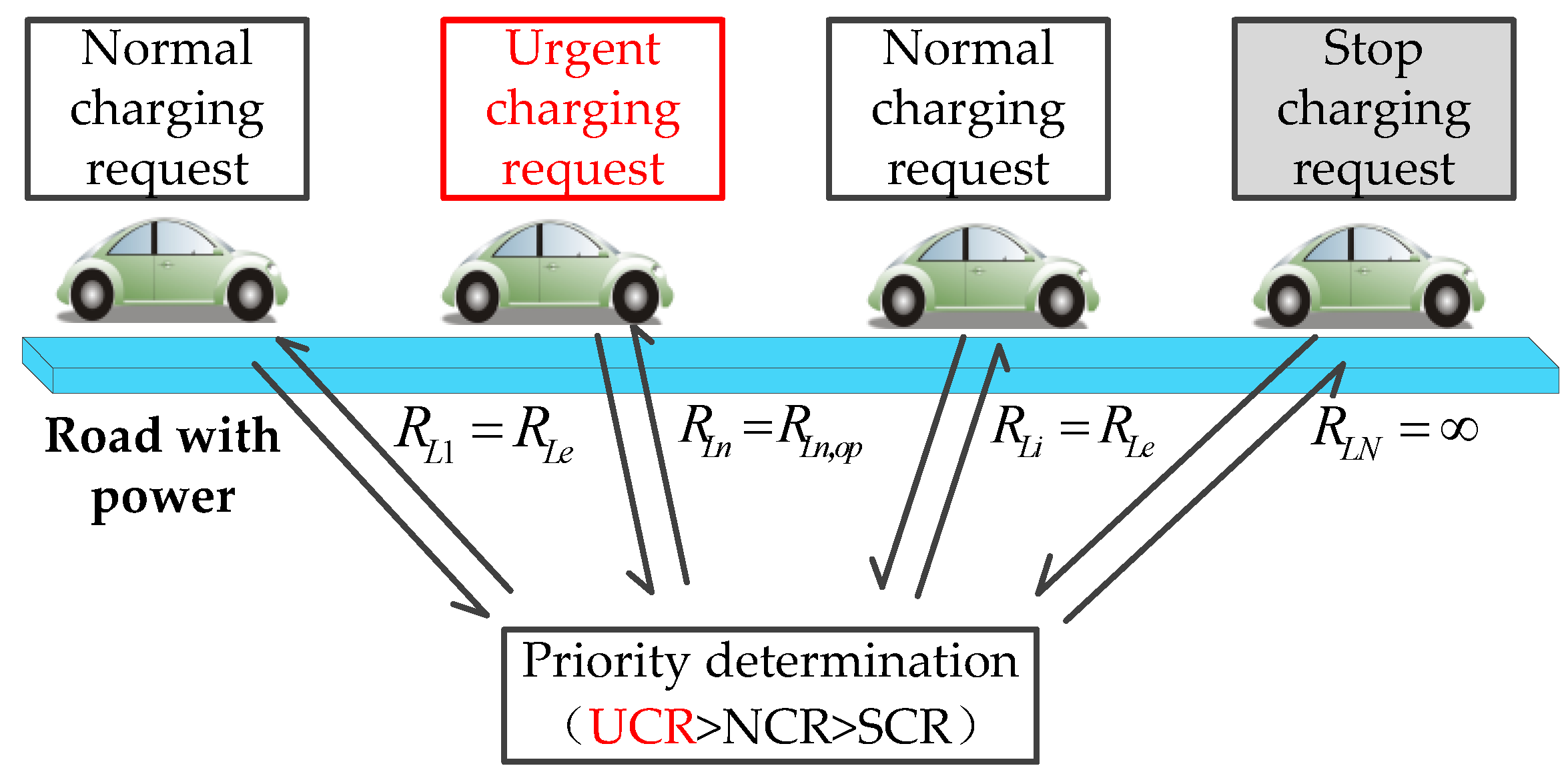
3.2.3. Particular Power Demand

The main premise of the power control strategy discussed above is that all of the equivalent load resistances are identical. This strategy can not only achieve high transfer efficiency, but also maximize the utilization of the sectional track. Nevertheless, some urgent charging requests should be taken into account for a particular EV whose battery capacity is pretty low. As a consequence, a power control strategy by adjusting load resistance is presented to regulate the power distribution.
In circumstances where there are no urgent charging requests, all of the equivalent load resistances are adjusted to the optimal resistance expressed by Equation (10). In the case of a particular power demand, the receiving power of the EV with low battery capacity is expressed by:
P n = ω 2 M 0 2 U 0 2 R L n ( R L n + R 1 ) 2 ( R 0 + ω 2 M 0 2 i = 1 N 1 / ( R L i + R 1 ) ) 2
By substituting D for R 0 + ω 2 M 0 2 i = 1 , i n N 1 / ( R L i + R 1 ) , Equation (14) is simplified into:
P n = ω 2 M 0 2 U 0 2 R L n ( R L n + R 1 ) 2 ( D + ω 2 M 0 2 R L n + R 1 ) 2 = ω 2 M 0 2 U 0 2 ( ω 2 M 0 2 + R 1 D ) 2 R L n + R L n D 2 + 2 R 1 D 2 + 2 D ω 2 M 0 2
It can be deduced that P n at first increases, but then decreases with R L n increasing, and will achieve a peak value when R L n , o p = ( ω 2 M 0 2 + R 1 D ) / D . The maximum receiving power is:
P n , max = ω 2 M 0 2 U 0 2 4 D ( R 1 D + ω 2 M 0 2 )
The adjustment of load resistance does have a significant impact on power distribution, providing a feasible way to deal with particular power demand. Different charging requests can be met by corresponding adjustment of load resistance. The working principle of the control strategy is illustrated in Figure 7 and a brief introduction of working steps are as follows: (1) the upcoming EV will send a charging request (urgent charging request, normal charging request) to the control center on the primary side in advance. The leaving EV will also send a charging request (stop charging request) to the control center; (2) after the control center receives the charging requests, the corresponding adjustment of IMNs will be examined firstly to check whether it will bring a significant fluctuation to other EVs. If not, the permission will then be delivered to the corresponding EV. Otherwise no adjustments are carried out.

4. Experimental Verifications

To validate the correctness of the proposed control strategy, a scaled-down experimental prototype is set up. The system works at 85 kHz, which is also the resonant frequency of the transmitting coil and receiving coils. Specific parameters are tabulated in Table 2. Receiving coils are placed with separated distances to represent the safe following distance, as shown in Figure 8. The measured mutual inductance between each receiving coil and transmitting coil, and that between each two receiving coils, is 4.425 μH and 5 × 10⁻³ μH, respectively. As a result, the mutual inductance between each two receiving coils can be ignored, indicating inefficient coupling. The voltage is measured with a voltage probe Tektronix TPP0500B (Beaverton, OR, USA) and the current is measured with a current sensor Agilent N2783A (Santa Clara, CA, USA), which transforms current to voltage according to the proportion 0.1 V/1 A. Source voltage can be controlled by adjusting the radio frequency power amplifier, while the receiving power of each load can be calculated on the basis of the detected voltage and current.

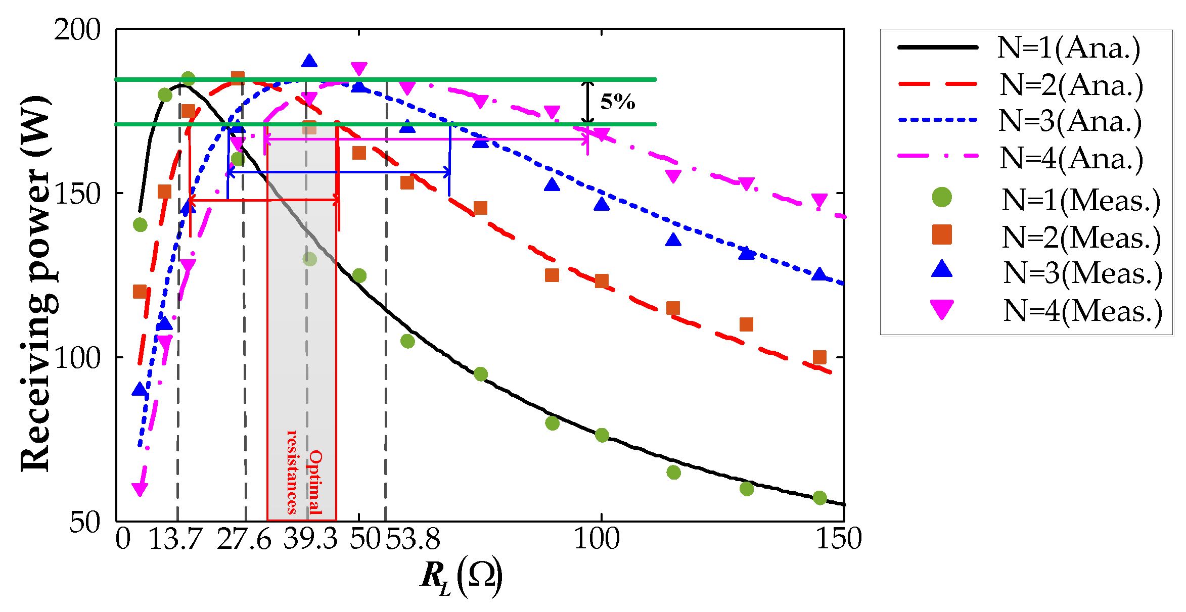
4.1. Output Power Optimization

Figure 9 compares four cases with different amounts of receivers to investigate the relationship between receiving power of each receiver and load resistances. When the number of receivers is constant, maximum receiving power can be achieved at a certain load resistance, as predicted in Equation (7). The optimal resistances of a system with N (N = 1,2,3,4) receivers are 13.7 Ω, 27.6 Ω, 39.3 Ω, and 53.8 Ω, respectively. Corresponding measured results are 10 Ω, 25 Ω, 40 Ω, and 50 Ω, keeping approximately consistent with the theoretical analysis.
It can be seen that there is a deviation between optimal resistances of different numbers of receivers, which is not convenient enough for practical applications. The paper then suggests that part of the transfer power can be sacrificed to achieve a broader range of optimal resistances. Take the case when the receiver numbers vary between two and four, for instance; if a 5% decrease of transfer power is acceptable, the optimal resistances for different numbers of receivers can be determined by the coordinate interval indicated by the same color, as shown in Figure 9. There is an overlap of the coordinate intervals for different numbers of receivers, obviously, as presented by the solid shadow. Thus, this part of the optimal resistances can be chosen to set the rated load resistance for each receiver.

4.2. Receiving Power Control with Self-Adaptive Source Voltage

This part of the experiment is performed to verify the feasibility of a power control strategy with self-adaptive source voltage. Specifically, the number of receiving coils is varied from N = 2 to N = 4. With reference to Figure 9, all of the load resistances are set to 40 Ω since the receiving power varies least for different EV numbers (N = 2 to N = 4). Both the source voltage and the voltage of load ① are monitored with voltage probes. If there is any variation of the voltage of load ①, the source voltage will be adjusted until the voltage of load ① reaches the rated value.
Figure 10 displays the measured results of source voltages and the load voltage ① for different numbers of receivers. The red curve and blue curve represent the source voltage and load voltage ①, respectively. To maintain the load voltage ① around 40 W, effective values of the source voltage should be adjusted to 20.5 V, 23.6 V, and 26.4 V for different numbers of receivers, as explained in Equation (14). Compared with theoretical results, experimental results show that when peak values of the source voltage are set to 29.0 V, 33.4 V, and 37.4 V, respectively, output power of about 43.5 W can be maintained stably when the number of receiving coils changes from N = 2 to N = 4, proving the correctness of the theoretical analysis.

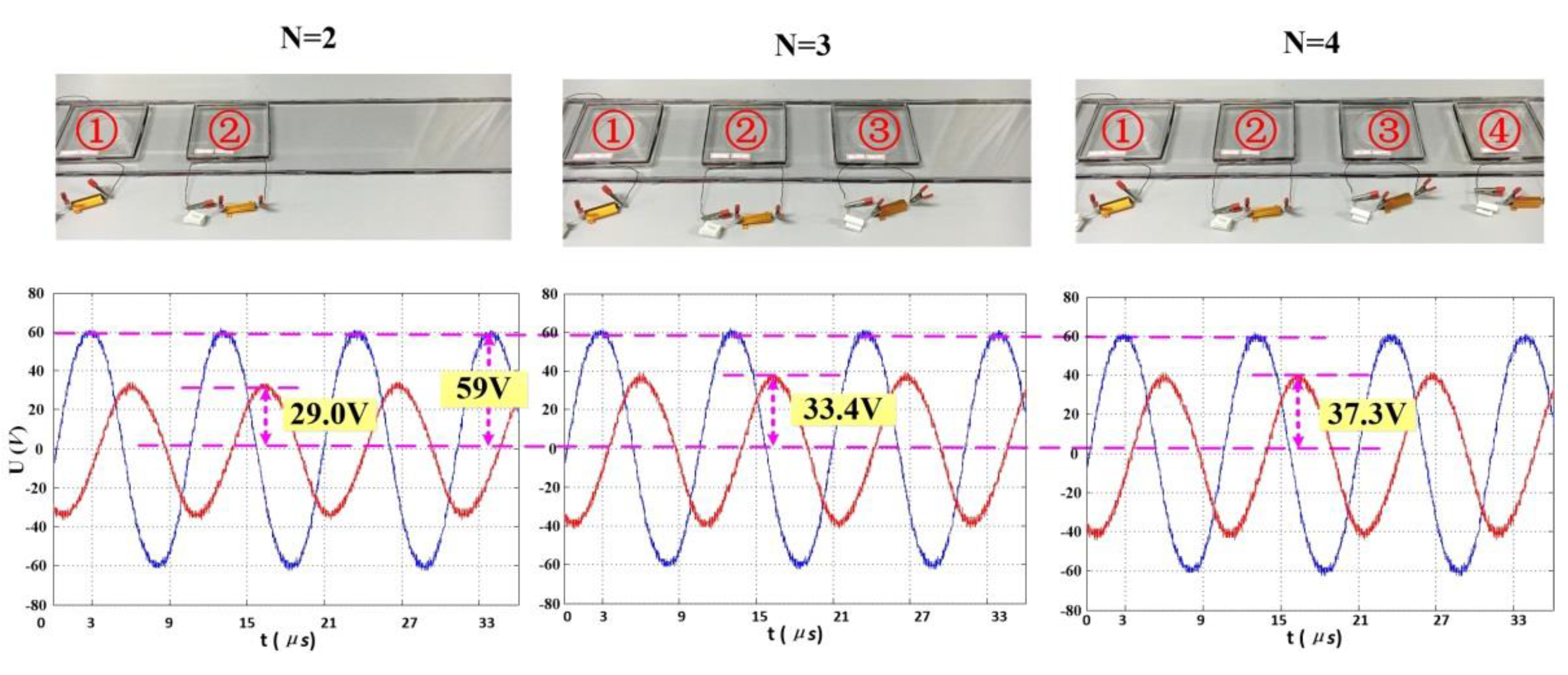
4.3. Receiving Power Control with Adjustment of Load Resistance

Four identical receiving coils are used to verify the control of receiving power with an adjustment of load resistance. Source voltage is fixed at U 0 = 20 V and load resistances are set as 40 Ω. It is assumed that load ① is in dire need of quick charging and is defined as an adjustable load, and other loads with fixed resistance are defined as fixed loads. The receiving power of each fixed load and that of adjustable load are defined as P f and P a , respectively. Figure 11 compares P f and P a when the resistance of load ① R L 1 is adjusted from 1 Ω to 100 Ω.
It shows that P f increases with R L 1 increasing, while P a increases first, and then decreases with R L 1 increasing. The intersection of P f and P a is represented by point 1, indicating that all loads receive equal power. Point 2 in Figure 11 represents the corresponding resistance where P a achieves its maximum value. To meet the urgent charging request of load ①, a feasible method is to regulate the resistance from point 1 to point 2. Measured results show that P a increases from 28.6 W to 69.1 W by regulating R L 1 from 40 Ω to 5 Ω, which is consistent with theoretical values. It is also noted that, despite the receiving power increase of load ①, the receiving power of each other load drops from 28.6 W to 9.2 W. As a result, this power control strategy can only serve in emergent cases.
System efficiency is also measured and results are specifically displayed in Figure 12. Power loss is caused mainly by the coil inner resistances and can be reduced by designing coils with a high quality factor. It is noted that system efficiency is enhanced from 49.4% to 71.9% by adjusting R L 1 from point 1 to point 2. The reason why point 1 presents a relatively low efficiency is that the system is designed on the basis of a maximum power transfer criteria [23]. Efficiency can be improved by adjusting the impedance according to a maximum energy efficiency criteria, which should also be considered in a practical application.

5. Discussion

Wireless charging for EVs presents a potential in extending driving range and reducing battery capacity, especially when on-road charging can be implemented. In the paper, the problem of charging several EVs simultaneously is analyzed thoroughly. The optimal resistance, which can be regulated by the impedance matching network, is first derived according to different EV numbers to guarantee maximum receiving power for each charging EV. Taking the practical applications into consideration, self-adaptive source voltage is proposed to deal with the cases when the number of EVs in the charging section changes. In addition, for congested traffic conditions where EV charging numbers exceed the designed value, a feasible power supply method is introduced to compensate for power consumption. It is also noted that several other issues are of great concern. On the one hand, primary power control and battery management regarding different charging statuses, such as the misalignment between coils, various charging demands should be further assessed. On the other hand, impedance matching based on maximum energy efficiency should also be taken into consideration in a practical application. In particular, the problem of the electromagnetic environment of on-road charging systems with such a dimension is what we need to tackle in the future. The feasibility to mitigate electromagnetic forces to satisfy safety constraints is of great interest. Furthermore, the prospect of on-road charging technology is promising, considering its convenience and its significant role in promoting the mass applications of EVs.

6. Conclusions

This paper has proposed an on-road charging system with a single transmitting coil and multiple receiving coils. For maximum receiving power of each EV for a system with identical loads, the resistances should be adjusted according to the number of charging EVs. Avoiding excessive primary current and satisfying a minimum charging demand are taken into consideration to determine the power control strategy. Specifically, self-adaptive source voltage and constant source voltage are applied to charge different numbers of EVs, respectively, due to different traffic conditions. To charge each EV with rated power when the voltage source can support enough charging EVs, adjustment of the source voltage based on primary current detection is proposed. As for congested traffic with too many EVs, the source is regulated to maximum output and EVs are permitted to charge according to the first come, first serve rule. In addition, a balanced speed is used as guidance for drivers to adjust the individual driving speed to acquire efficient energy compensation. In the case of a particular power demand, the corresponding resistance is adjusted from the point of the average power distribution to the point of maximum power. We show by experiments that the proposed optimization of efficiency and power control strategies perform close to the theoretical analysis, applying to systems with different topologies or parameters. As a concluding remark, an on-road charging system including a single TX and multiple RXs can serve as an efficient way to make up for EV power loss.

Acknowledgments

This work was supported in part by National Nature Science Youth Foundation of China (No. 51507032), Nature Science Youth Foundation of Jiangsu Province (No. BK20150617) and the Fundamental Research Funds for the Central Universities.

Author Contributions

Linlin Tan proposed the research topic and designed the model. Jinpeng Guo performed the calculation and analyzed the data. Xueliang Huang, Han Liu helped to organize the paper and carry out the experimental measurement. Changxin Yan and Wei Wang took part in validating the idea and revising the paper. All authors contributed to the writing of the manuscript, and have read and approved the final manuscript.

Conflicts of Interest

The authors declare no conflict of interest.

References

  1. Choi, S.Y.; Gu, B.W.; Jeong, S.Y.; Rim, C.T. Advances in Wireless Power Transfer Systems for Roadway-Powered Electric Vehicles. IEEE J. Emerg. Sel. Top. Power Electron. 2015, 3, 18–36. [Google Scholar] [CrossRef]
  2. Onar, O.C.; Miller, J.M.; Campbell, S.L.; Coomer, C.; White, C.P.; Seiber, L.E. A novel wireless power transfer for in-motion EV/PHEV charging. In Proceedings of the 2013 Twenty-Eighth Annual IEEE Applied Power Electronics Conference and Exposition (APEC), Long Beach, CA, USA, 17–21 March 2013.
  3. Covic, G.A.; Boys, J.T. Modern Trends in Inductive Power Transfer for Transportation Applications. IEEE J. Emerg. Sel. Top. Power Electron. 2013, 1, 28–41. [Google Scholar] [CrossRef]
  4. Chen, Z.; Jing, W.W.; Huang, X.L.; Tan, L.L.; Chen, C.; Wang, W. A Promoted Design for Primary Coil in Roadway-Powered System. IEEE Trans. Magn. 2015, 51, 1–4. [Google Scholar] [CrossRef]
  5. Li, S.; Mi, C.C. Wireless Power Transfer for Electric Vehicle Applications. IEEE J. Emerg. Sel. Top. Power Electron. 2015, 3, 4–17. [Google Scholar]
  6. Miller, J.M.; Jones, P.T.; Li, J.; Onar, O.C. ORNL Experience and Challenges Facing Dynamic Wireless Power Charging of EV’s. IEEE Circuits Syst. Mag. 2015, 15, 40–53. [Google Scholar] [CrossRef]
  7. Chopra, S.; Bauer, P. Driving Range Extension of EV with On-Road Contactless Power Transfer—A Case Study. IEEE Trans. Ind. Electron. 2013, 60, 329–338. [Google Scholar] [CrossRef]
  8. Nagendra, G.R.; Covic, G.A.; Boys, J.T. Determining the Physical Size of Inductive Couplers for IPT EV Systems. IEEE J. Emerg. Sel. Top. Power Electron. 2014, 2, 571–583. [Google Scholar] [CrossRef]
  9. Bosshard, R.; Kolar, J.W.; Muhlethaler, J.; Stevanovic, I.; Wunsch, B.; Canales, F. Modeling and η-α-Pareto Optimization of Inductive Power Transfer Coils for Electric Vehicles. IEEE J. Emerg. Sel. Top. Power Electron. 2015, 3, 50–64. [Google Scholar] [CrossRef]
  10. Tan, L.L.; Huang, X.L.; Zhao, J.F.; Zhao, J.M.; Wang, W.; Zhou, Y.L. Optimization Design for Disc Resonators of a Wireless Power Transmission System. Trans. China Electrotech. Soc. 2013, 28, 1–6. [Google Scholar]
  11. Li, W.H.; Zhao, H.; Li, S.Q.; Deng, J.J.; Kan, T.Z.; Mi, C.C. Integrated LCC Compensation Topology for Wireless Charger in Electric and Plug-in Electric Vehicles. IEEE Trans. Ind. Electron. 2015, 62, 4215–4225. [Google Scholar] [CrossRef]
  12. Zhu, Q.W.; Wang, L.F.; Liao, C.L. Compensate Capacitor Optimization for Kilowatt-Level Magnetically Resonant Wireless Charging System. IEEE Trans. Ind. Electron. 2014, 61, 6758–6768. [Google Scholar] [CrossRef]
  13. Li, S.Q.; Li, W.H.; Deng, J.J.; Nguyen, T.D.; Mi, C.C. A Double-Sided LCC Compensation Network and Its Tuning Method for Wireless Power Transfer. IEEE Trans. Veh. Tech. 2015, 64, 2261–2273. [Google Scholar] [CrossRef]
  14. Hao, H.; Covic, G.A.; Boys, J.T. An Approximate Dynamic Model of LCL-T-Based Inductive Power Transfer Power Supplies. IEEE Trans. Power Electron. 2014, 29, 5554–5567. [Google Scholar] [CrossRef]
  15. Wu, H.H.; Gilchrist, A.; Sealy, K.D.; Bronson, D. A High Efficiency 5 kW Inductive Charger for EVs Using Dual Side Control. IEEE Trans. Ind. Inform. 2012, 8, 585–595. [Google Scholar] [CrossRef]
  16. Madawala, U.K.; Neath, M.; Thrimawithana, D.J. A Power–Frequency Controller for Bidirectional Inductive Power Transfer Systems. IEEE Trans. Ind. Electron. 2013, 60, 310–317. [Google Scholar] [CrossRef]
  17. Gao, Y.; Farley, K.B.; Tse, Z.T.H. A uniform voltage gain control for alignment robustness in wireless EV charging. Energies 2015, 8, 8355–8370. [Google Scholar] [CrossRef]
  18. Nagendra, G.R.; Chen, L.; Covic, G.A.; Boys, J.T. Detection of EVs on IPT Highways. IEEE J. Emerg. Sel. Top. Power Electron. 2014, 2, 584–597. [Google Scholar] [CrossRef]
  19. Kim, J.; Kim, D.; Park, Y. Analysis of Capacitive Impedance Matching Networks for Simultaneous Wireless Power Transfer to Multiple Devices. IEEE Trans. Ind. Electron. 2014, 62, 2807–2813. [Google Scholar] [CrossRef]
  20. Kurs, A.; Moffatt, R.; Soljacic, M. Simultaneous mid-range power transfer to multiple devices. Appl. phys. Lett. 2010, 96, 044102. [Google Scholar] [CrossRef]
  21. Zhang, Y.M.; Lu, T.; Zhao, Z.M.; Chen, K.N.; He, F.B.; Yuan, L.Q. Wireless Power Transfer to Multiple Loads Over Various Distances Using Relay Resonators. IEEE Microw. Wirel. Compon. Lett. 2015, 25, 337–339. [Google Scholar] [CrossRef]
  22. Lee, K.; Cho, D. Analysis of Wireless Power Transfer for Adjustable Power Distribution among Multiple Receivers. IEEE Antennas Wirel. Propag. Lett. 2015, 14, 950–953. [Google Scholar] [CrossRef]
  23. Hui, S.Y.R. Magnetic Resonance for Wireless Power Transfer [A Look Back]. IEEE Power Electron. Mag. 2016, 3, 14–31. [Google Scholar] [CrossRef]
  24. Chen, C.J.; Chu, T.H.; Lin, C.L.; Jou, Z.C. A Study of Loosely Coupled Coils for Wireless Power Transfer. IEEE Trans. Circuits Syst. II: Express Briefs 2010, 57, 536–540. [Google Scholar] [CrossRef]
  25. Fu, M.; Zhang, T.; Ma, C.; Zhu, X. Efficiency and Optimal Loads Analysis for Multiple-Receiver Wireless Power Transfer Systems. IEEE Trans. Microw. Theory Tech. 2015, 63, 801–812. [Google Scholar] [CrossRef]
  26. Pantic, Z.; Lukic, S.M. Framework and Topology for Active Tuning of Parallel Compensated Receivers in Power Transfer Systems. IEEE Trans. Power Electron. 2012, 27, 4503–4513. [Google Scholar] [CrossRef]
  27. Kusaka, K.; Itoh, J. Experimental verification and analysis of AC-DC converter with an input impedance matching for wireless power transfer systems. In Proceedings of the 2013 15th European Conference on Power Electronics and Applications (EPE), Lille, France, 2–6 September 2013.
  28. Lim, Y.; Tang, H.; Lim, S.; Park, J. An Adaptive Impedance-Matching Network Based on a Novel Capacitor Matrix for Wireless Power Transfer. IEEE Trans. Power Electron. 2013, 29, 4403–4413. [Google Scholar] [CrossRef]
  29. Duong, T.P.; Lee, J. A dynamically adaptable impedance-matching system for midrange wireless power transfer with misalignment. Energies 2015, 8, 7593–7617. [Google Scholar] [CrossRef]
  30. Prasanth, V.; Bauer, P. Study of misalignment for On Road Charging. In Proceedings of the 2013 IEEE Transportation Electrification Conference and Expo (ITEC), Detroit, MI, USA, 16–19 June 2013.
  31. Zhang, W.; Wong, S.; Tse, C.K.; Chen, Q.H. A study of sectional tracks in roadway inductive power transfer system. In Proceedings of the 2011 IEEE Energy Conversion Congress and Exposition, Phoenix, AZ, USA, 17–22 September 2011.
  32. Byd Electric Vehicles, Photovoltaic, LED Lighting, Energy Storage. Available online: http://bydauto.com/ (accessed on 10 June 2016).
  33. Budhia, M.; Covic, G.A.; Boys, J.T. Design and Optimization of Circular Magnetic Structures for Lumped Inductive Power Transfer Systems. IEEE Trans. Power Electron. 2011, 26, 3096–3108. [Google Scholar] [CrossRef]
Figure 1. Diagram of an on-road charging for EVs.
Energies 09 00531 g001
Figure 2. Equivalent circuit of an on-road charging system.
Energies 09 00531 g002
Figure 3. Primary current and receiving power according to EV numbers.
Energies 09 00531 g003
Figure 4. Receiving power per EV versus source voltage when the number of EV varies from 3–7.
Energies 09 00531 g004
Figure 5. (a) Flowchart of source voltage adjustment. (b) I0 and U0 according to time (t1 represent the time when the number of charging EVs changes and t2 represents the time when output voltage of the source is adjusted.)
Energies 09 00531 g005
Figure 6. Charging energy of each EV according to driving speeds per km.
Energies 09 00531 g006
Figure 7. Communication of charging requests and control order of an on-road charging system.
Energies 09 00531 g007
Figure 8. Configuration of the designed scaled-down experimental prototype.
Energies 09 00531 g008
Figure 9. Receiving power versus load resistance for different numbers of EVs.
Energies 09 00531 g009
Figure 10. Voltages of source and load ① for different numbers of EVs.
Energies 09 00531 g010
Figure 11. Receiving power versus adjustable loads when N = 3.
Energies 09 00531 g011
Figure 12. Transfer efficiency versus adjustable loads when N = 3.
Energies 09 00531 g012
Table 1. Specific parameters of the designed on-road charging system.
Parameters Value
Source voltage 100V ~ 700V
Working frequency85 kHz
Wire radius5.89 mm
Size of transmitter160 m × 1.2 m
Inductance of transmitter14.5 mH
Size of receiver1 m × 1 m
Inductance of receiver153 μH
Table 2. Specific parameters of the designed prototype.
Parameters Value
Working frequency85 kHz
Size of transmitter1 m × 0.2 m
Inductance of transmitter74.8 μH
Compensated capacitor of transmitter47 nF
Size of receiver0.2 m × 0.2 m
Inductance of receiver21.4 μH
Compensated capacitor of receiver168 nF

