1. Introduction
The penetration of wind energy increases rapidly with the in-depth study and technical progress on wind power generation in recent years, however, large-scale penetration of wind power will change the damping characteristics of grid, thus the low signal stability of the network under high wind power penetration level is more sensitive than that of the traditional grid [
1,
2,
3].
The doubly fed induction generator (DFIG) has gained increasing popularity in wind power generation recently due to its flexible controllability and relatively low price. Although the impact of power system oscillation on DFIG can be inhibited by power electronic converter, the volatility of wind power and the tripping of wind generators without low voltage ride through (LVRT) capability increase the oscillation power suffered by synchronous machines in the regional grid, thus making power systems more likely to suffer chronic oscillation. Therefore, it is of great significance for the secure and stable operation of regional grid with high wind power penetration to increase the inhibitive capability of power system oscillation by improving the existing control strategies of variable speed wind turbines [
4,
5,
6,
7,
8].
In fact, current PSS control strategies to enhance operational stability of grids cannot have had full effect since the operation of traditional synchronous generators needs to consider other control demands such as voltage regulation and frequency regulation except for stability control, which is always contradiction with aims and instructions of PSS. However, wind generators normally have less output control demand, and can respond to the damping control effectively, which is very suitable for the project implementation of small signal stability optimal control strategy in power grid with high wind penetration.
References [
9,
10,
11,
12,
13,
14] have studied the controller design for DFIG to increase the damping of the system. In reference [
9], pitch control is utilized to design a damping controller based on P/f droop control, in which the deviation of frequency is used to adjust pitch angle and change the amount of captured wind energy, thus adjusting the power of wind turbine based on oscillation of frequency. However, the response speed of pitch control is too slow to suppress the oscillation of the system effectively. In [
10], the auxiliary signal derived from ω
r is added to the rotor phase angle control, which can enhance not only the low-frequency damping of the system, but also the LVRT capability of the wind generator. Reference [
11] reduces the impact of a DFIG wind turbine on a regional grid through the control of rotor flux amplitude and the phase of DFIG, which is similar to dynamic excitation and power angle characteristics of a gel synchronous generator. [
12,
13] proposes a control mechanism aimed at designing the power system stabilizer (PSS) for a DFIG, whose input signal is the DFIG terminal voltage, system oscillation power, and deviation of rotational speed of synchronous generator, respectively. Reference [
14] investigates the principle of improving the system damping through the power regulation of the PMSG-based wind turbines, and proposes the active and the reactive power damping control strategies, which enhances system damping by adding proportional control based on the deviation of system frequency to rotor speed of MPPT control. However, only proportional control would produce some steady-state error to power the angle of a synchronous generator.
Aiming at the small signal stability problem in large-scale penetration of wind power into power systems, in this paper, the dynamic model of the doubly fed induction generator (DFIG) is established firstly, to analyze the impact of wind generation on power oscillation damping. Then, based on the conventional maximum power point tracking control of variable speed wind turbine, a supplementary control scheme is proposed to increase the damping of power system. To achieve best performance, parameters of the damping control are tuned by using a genetic algorithm. Results of eigenvalue analysis and simulation on Western Systems Coordinating Council (WSCC) three-machine nine-bus system with an integrated DFIG demonstrate that the proposed supplementary control scheme can effectively suppress the oscillation of the system in fixed wind speeds.
Finally, the above damping control is improved by making the additional active power constant with the variation of operational point of wind generator, due to the problem that varying power output of the wind generator caused by randomness of wind speed would cause the control effect unstable, which is not only contributive to the system power oscillation, but also counterproductive to the whole system. Results of contrast simulation verify the insensitivity of new damping control schemes to the change of wind speed and significant enhancement of system stability.
2. DFIG Model and Control System
The sketch diagram [
15] in
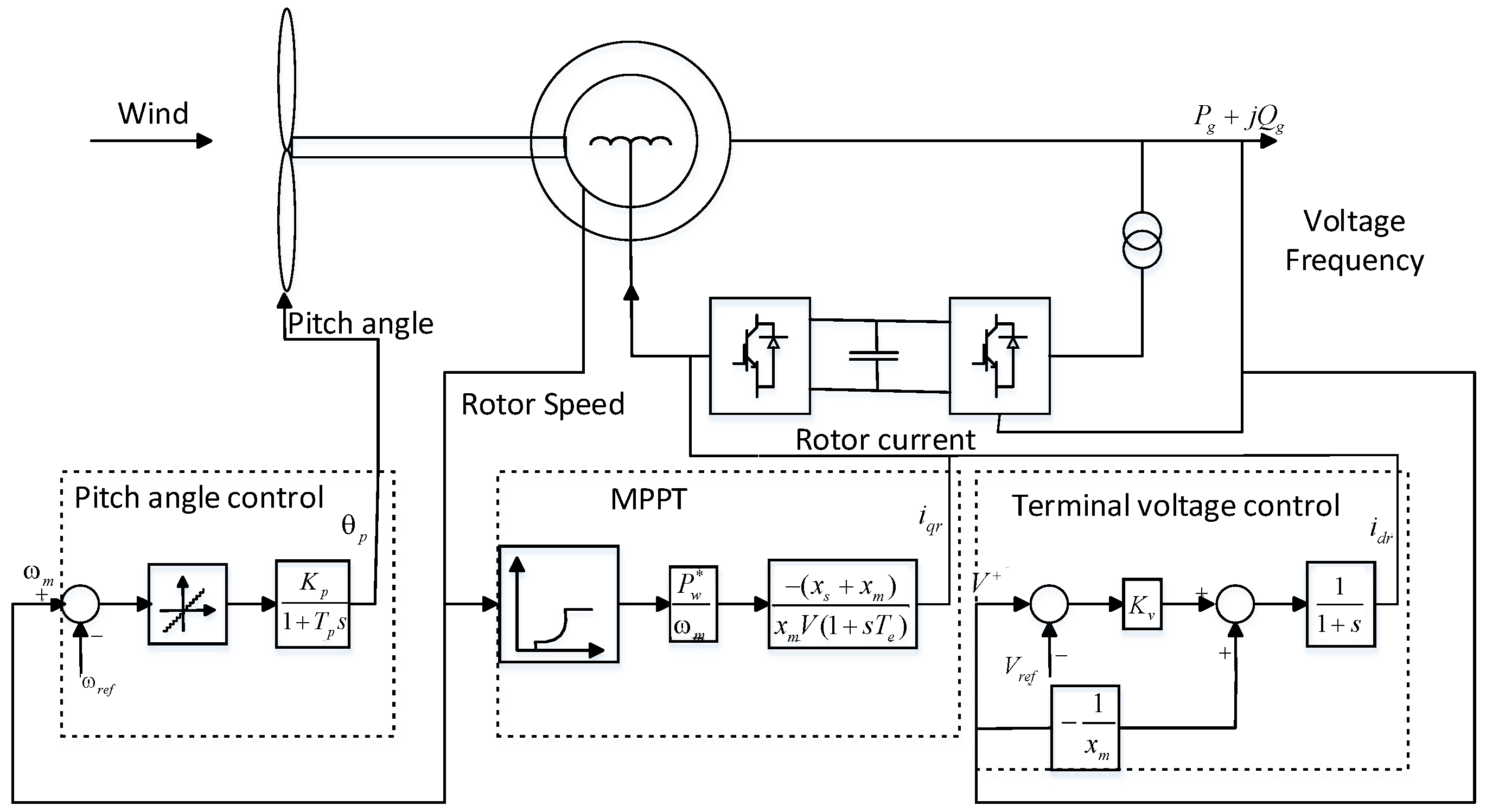
Figure 1 shows a DFIG-based wind power generation system. As shown in
Figure 1, stator side of DFIG connects to the grid through a transformer, while the rotor side connects to the grid through back to back convertor, which achieves the decoupling of rotor speed and grid frequency and the convertor compensates the difference between mechanical and electrical frequency by injecting variable frequency rotor current. DFIG dynamic modeling is mainly divided into three parts: the mechanical part, doubly-fed generator, and controller [
16].
The doubly-fed generator rotor is driven by the rotating of wind turbine blades through a gear box, whose electromechanical equation is modeled in (1):
Ignore the stator
Figure 1, and assume d-axis is consistent with the direction of maximum value of stator flux, then the electromagnetic torque equation can be simplified as (2):
Mechanical torque equation is shown in (3):
Neglect rotor transients, then the convertor model can be simplified properly. Model the back to back voltage convertor with current loop as an ideal current source, then the relationship of voltage and current of generator rotor and stator are shown in Equation (4), where subscript ‘
s’ represents parameters related to stator and subscript “
ν” represents parameters in grid side of convertor. The
rs,
xs,
rR, and
xR are resistance and leakage reactance of stator and rotor,
wb is the angular velocity of the DFIG rotor when frequency and
xm is the excitation reactance of DFIG.
With stator resistance being neglected and the direction of maximum value of stator flux, determining the position of d axis, the power injected to the grid can be equivalent to Equations (5) and (6):
As shown in
Figure 1, DFIG adjusts the speed of wind turbine blades by maximum power point tracking to achieve active power control. First, get theoretical maximum power output
Pw according to the angular speed-output power curve by measured rotor speed, then, achieve control objective by adjusting inverter current. The control equation is shown in (7):
As shown in
Figure 1, DFIG changes the terminal voltage by controlling the reactive power in exchange with the grid. The control equation is in (8):
As shown, in lower left part of
Figure 1 is the pitch control. Once wind speed is higher than rated speed, variable pitch control can effectively regulate the pitch angle to limit the aerodynamic efficiency of the wind turbine blades to prevent wind wheel speed from getting too high and causing mechanical damage. The control equation is shown in (9):
3. Theory of Power System Low Frequency Oscillation
Small signal stability is the ability of power system to keep pace in the case of small perturbations which means that the effect caused by disturbance is too small to affect the structure of analysis model. The power system experiences small disturbance every time, such as random fluctuation of loads, slow change of some parameters and so on. Therefore, the ability of small signal stability is a necessity for a well-designed power system.
Power system generally can be described by nonlinear differential algebraic equations (DAE) as follows [
17]:
The first equation of DAE is state equation, and the second one is algebraic equation.
The above non-linear model can be linearized at the operating point and can be represented by incremental differential algebraic equations in the case of small perturbations as shown in Equation (11)
Then the eigen matrix of system is shown in Equation (12)
As it is well known, the stability of linear systems depends on the eigenvalues of state matrix As. Based on the first law of Lyapunov, if all eigenvalues of state matrix As have negative real parts, the system is asymptotically stable; conversely, if the system has at least one positive real part eigenvalues, the system is unstable; and the system is critical stable if the real part of at least one eigenvalue is zero when other eigenvalues have negative real parts. In addition, the eigenvectors and participation factors corresponding to eigenvalues can provide more system information for the inhibition of low frequency oscillation and the design of a small signal stability controller.
From state matrix
As, a certain number of eigenvalues can be calculated out and each eigenvalue corresponds to a mode: real eigenvalues correspond to non-oscillation mode, complex eigenvalues with negative real parts correspond to decay mode, and it is compared with its positive real part corresponding to aperiodic instability. Complex eigenvalues are as follows:
Real part of complex eigenvalue describes the system oscillation damping and imaginary part means the oscillation frequency. The oscillation frequency and damping ratio can be expressed as follows:
Damping determines the stability characteristics of system and the system can provide sufficient damping to keep the system stable only if damping is bigger than zero.
4. Optimal DFIG Control under Fixed wind Speed
4.1. Supplementary Damping Control of DFIG
As it is well known, synchronous generators and constant speed wind turbines are integrated with the grid and their stability is easily affected by the status of power system. On the contrary, the rotor speed of DFIG whose rotor side is excited by a power electronic convertor does not couple with the frequency of the grid. The active power output of variable speed wind generator is only controlled by wind speed, thus DFIG has no inhibitory effect on low frequency oscillation, and the dynamic process of power system will inevitably lack power support in areas under the high penetration level.
Once disturbance or failure occurs, the volatility of wind power in the area of high wind power penetration will increase the oscillation power such that a synchronous machine suffers in the case of insufficient damping in synchronous machine, which is more likely to cause the system to remain volatile.
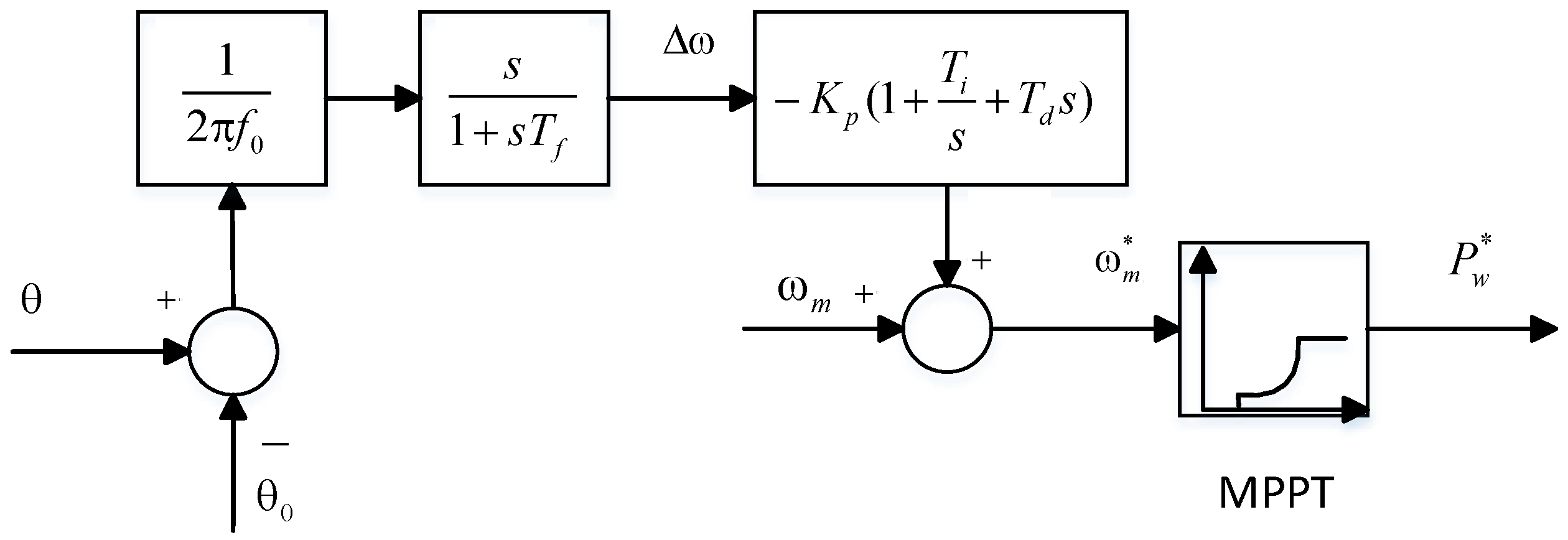
The block diagram of supplementary control is shown in
Figure 2. It is proved in [
14] that the adjustment of active power of DFIG can generate an additional damping torque for the swing of power angle of synchronous generators, thus increasing the damping of system. θ is the phase angle of terminal voltage of the bus DFIG connected, compare it with its initial value. Δω is the deviation of synchronous speed, and ω
m is the measured rotational speed.
4.2. Achievement of GA Optimization
To ensure dynamic performance of the system, especially for suppressing power oscillation, DFIG controller parameters should be well tuned. A genetic algorithm (GA) is used in this paper to tune parameters of damping control.
GA is a search heuristic that mimics the process of natural selection. This heuristic is routinely used to generate useful solutions to optimize and search for problems [
18]. Genetic algorithm belongs to the larger class of evolutionary algorithms (EA), which generate solutions to optimize problems using techniques inspired by natural evolution, such as inheritance, mutation, selection, and crossover.
Wind Power optimization control is a multi-variable, multi-constrained non-linear programming problem. A genetic algorithm (GA) with strong robustness and adaptive searching capabilities on wind power optimization control can search the optimal solutions based on all continuous and discrete control variables so that the complexity of calculation is reduced; GA can also avoid a premature local optimum, and reduce the corresponding amount of calculation to get globally optimal solution faster.
As described in
Section 4.1, damping ratio is an important index that measures the dynamic performance of system. In order to satisfy certain transient performance of system dynamics, it is more reasonable to set the damping ratio as optimization objective.
where
is the damping ratio of the
ith electromechanical mode, and
J is the smallest damping ratio among all the electromagnetic damping oscillation modes in some operating mode.
Constraint condition is:
where
p is the parameter vector defined as
p = [
Kp,
Ti,
Td] and
pmax and
pmin are the upper and lower limits, respectively, of the parameter vector. By using GA, the optimal controllers can be derived from the solution of optimization problem (16).
To minimize the objective function, the following classic GA procedure is employed:
Initialization of the population. N individuals represented by parameter vector “p” can be randomly generated. Minimum damping ratio of system electromechanical oscillation modes calculated according to the initial parameters of individual is defined as the fitness of the individual and the individuals are sorted based on the fitness in descending order.
Crossover and mutation. New individuals are generated by the exchange of different parts of gene of two parents selected by hybrid probability and then mutation operation is carried out on the new generated individuals.
Fitness value assessment. Calculate the minimum damping ratio of electromechanical oscillation mode as fitness of individual to assess all the descendants.
Choice. The top N individuals with maximum fitness values are chosen from the population after hybridization for breeding the next generation.
Stop. The algorithm stops when damping ratio of the best individual of the population can meet the requirements or genetic calculation exceeds the maximum algebra, otherwise goes back to step (2).
4.3. Simulation Studies
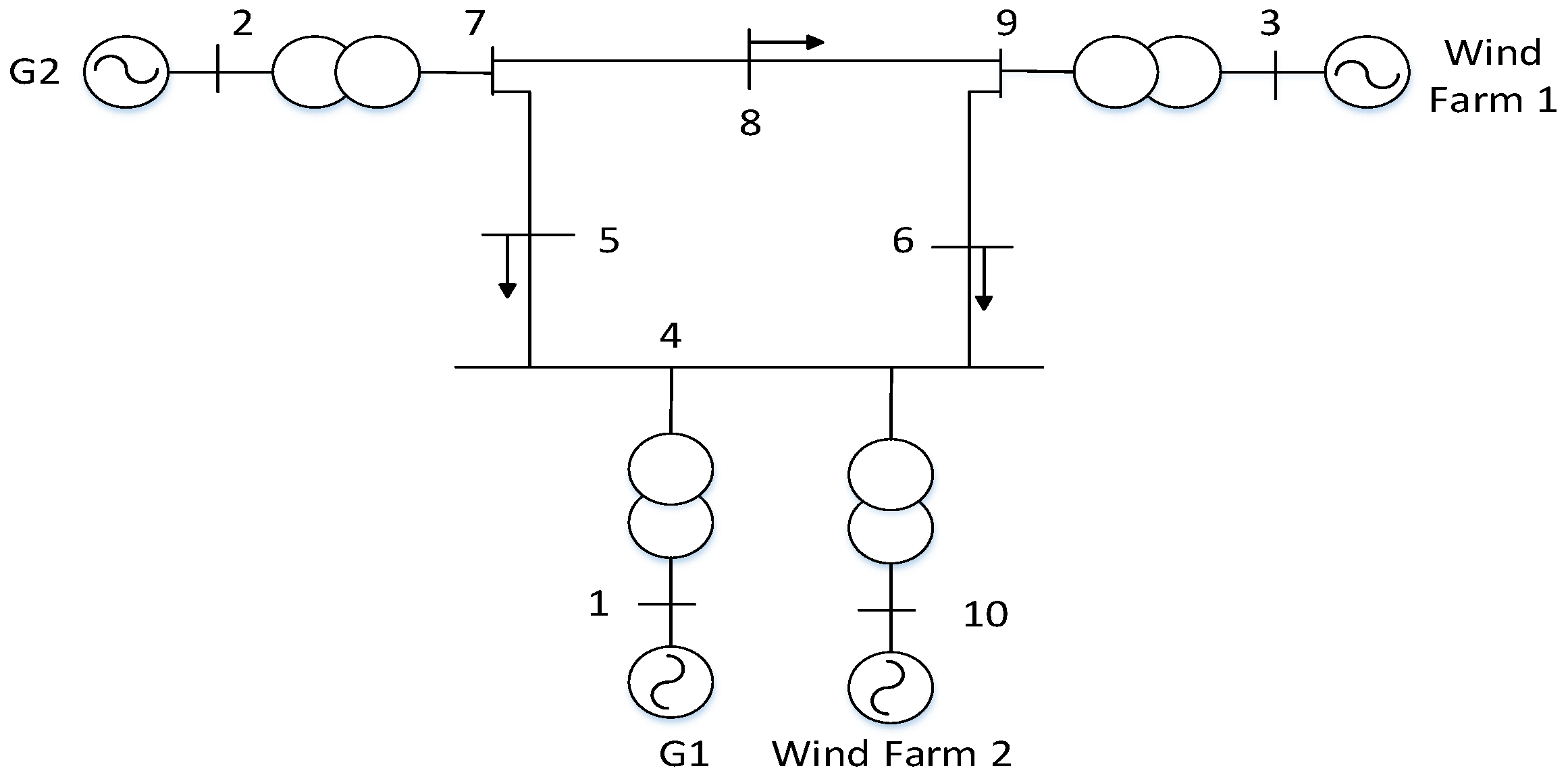
The case study system, as shown in
Figure 3, is the WSCC three-machine nine-bus system. There are two synchronous generators, with rated power of G1 100 MVA, and that of G2 300 MVA. All two synchronous generators are identical and equipped with turbine governors. The parameters of the synchronous generators are shown in
Table 1 of Appendix along with turbine governor control blocks and parameters. Two wind farms based on DFIG are connected to the grid in Bus 3 and Bus 10. Wind farm1 and wind farm2 are composed of 60 and 40 wind turbines (unit capacity 1.5 MW), and are respectively represented by one aggregated DFIG. Nodes 5, 6, and 8 are loads with constant power model, whose capacity is 160 + 80
j MVA, 200 MVA and 80 + 60
j MVA, respectively.
To verify the effectiveness of proposed DFIG supplementary damping control, GA is used to tune the damping control parameters. The population number is usually set as 10 times larger than the variable numbers, so it is set as 60 in this case. It is clear that the objective function can reach zero after about 30 generations of evolution. The optimization results are presented in
Table 1.
Electromechanical oscillation modes of system in
Figure 3 with and without DFIG damping control are shown in
Table 2.
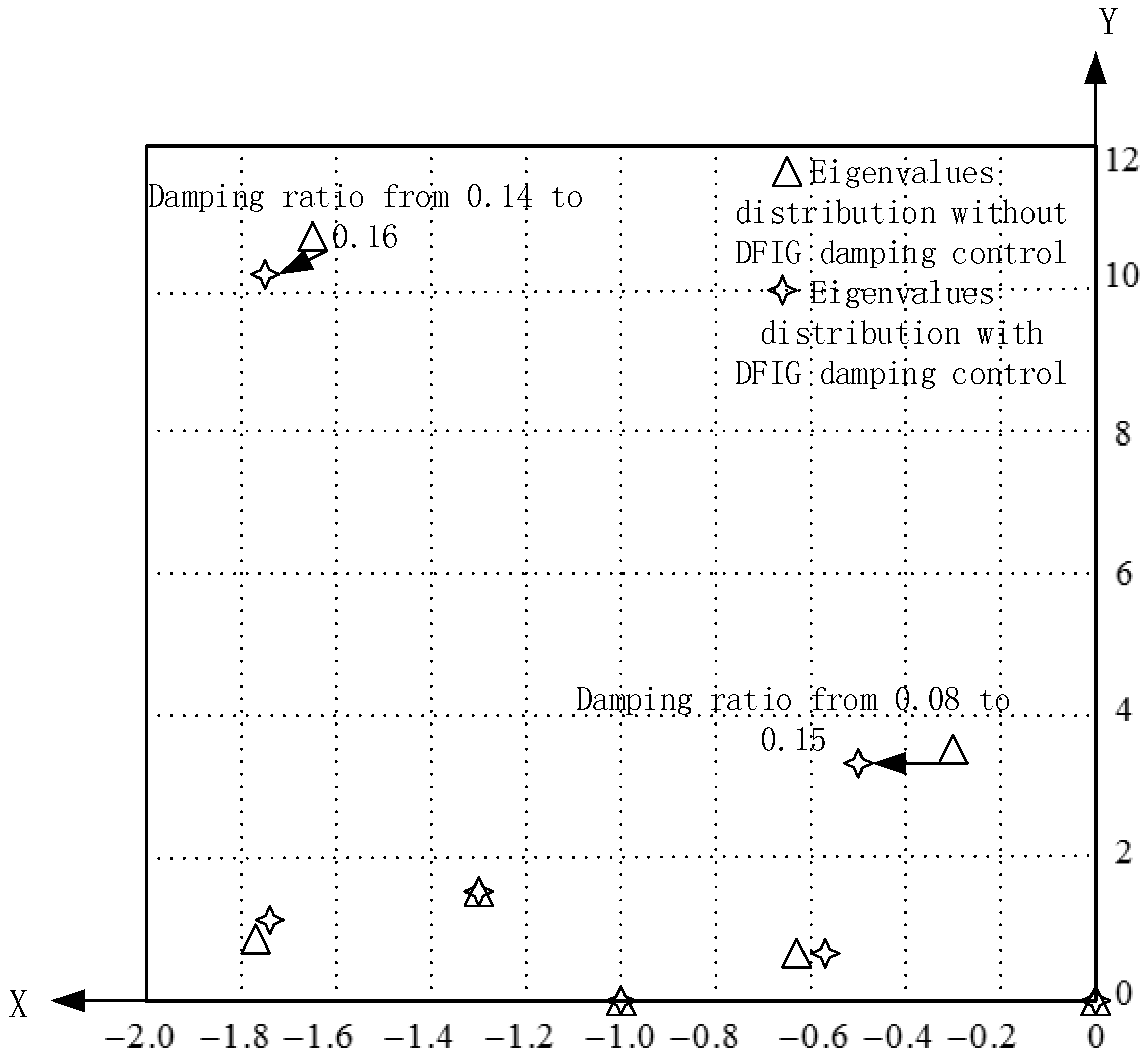
Distribution of partial eigenvalues for the two experiments is shown in
Figure 4. The triangles are eigenvalues of system without supplementary damping control (no damping control), which is the basic model described in
Section 2, and quadrangles are eigenvalues of systems with supplementary damping control, which is described in
Section 3. The arrows from triangles to quadrangles show the change of eigenvalues of electromagnetic oscillation modes. It is rather obvious that when there is no damping controller for the DFIG, the interarea oscillation is poorly damped. In contrast, the coordinately tuned supplementary damping controllers can make all the eigenvalues move to the desired region.
To further demonstrate the effectiveness of the proposed control scheme, several simulations are conducted. Add a power system stabilizer (PSS) in generator 1 [
18], then run a time-domain simulation in the case of adding supplementary damping control and no damping control in DFIG at Bus 2. Load at Bus 8 increases to 110% times of original value at 5 s, which means a small perturbation occurs at 5 s.
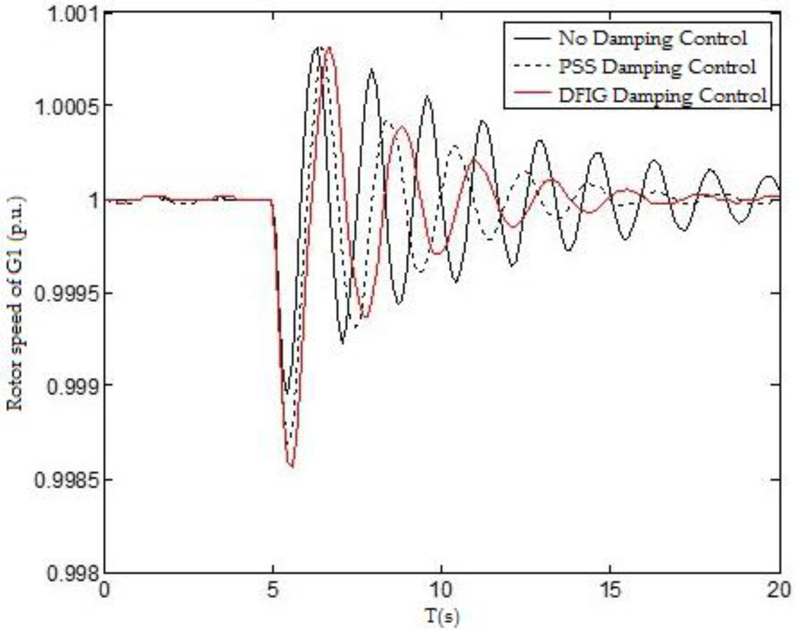
The rotor speed curves of the synchronous generator 1 under small perturbation in the case of PSS damping control, DFIG damping control, and no damping control are illustrated in
Figure 5. It can be seen that the rotor speed fluctuates on a small scale under small perturbation, and oscillation settles down much faster when adopting damping controls. Damping effect added in synchronous machine and DFIG with the same active power output can achieve approximately the same effectiveness, proving the performance of supplementary damping control of DFIG.
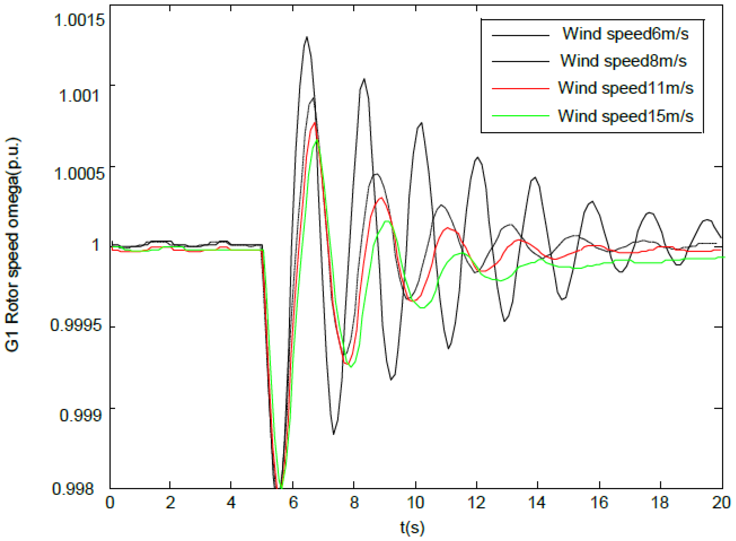
Observe from
Figure 5 that the oscillation suppression effect of DFIG supplementary damping control is not inferior to that of PSS in synchronous generator with the same active power output. In fact, active power output of DFIG is variable due to the volatility of wind speed. The response of rotor speed of generator 1 in the case of only DFIG damping control under small perturbation is illustrated in
Figure 6. Obviously, the oscillation suppression effect of DFIG damping control varies with different wind speeds, having a great impact on its practical application.
5. Optimal DFIG Control under Mutative Wind Speed
5.1. DFIG Supplementary Damping Control Scheme Considering Wind Speed Variation
Different from PSS in synchronous generator, the effect of wind generator supplementary damping control is not constant in fixed operation mode and varies as the change of wind speed. Namely, in areas where wind speed is volatile, utilization of wind generator supplementary damping control cannot inhibit the power oscillation effectively.
In
Section 3, the method of variable speed wind turbine to inhibit oscillation is to inject active power to the grid quickly to change the power angle of synchronous generator, thus enhancing low signal stability of system. Additional active power injected into the grid can reflect the control effect of wind generator supplementary damping control, and observe from the maximum power point the tracking scheme of
Section 1, mostly,
K is the optimal power output coefficient of a wind turbine. Simplify above polynomial on the right side, then the equation can be as follows:
where
K × ω
m3 is normal output of wind turbine generator, the polynomial in the right side is the supplementary output of the damping control. As ω
m is considerably larger than Δω
m, Equation (20) can be equivalent to
We can make Δω
m1 = Δω
m/ω
m2 and set Δ
P nearly constant, then the diagram of the improved DFIG damping control scheme is shown in
Figure 7.
5.2. Time-Domain Simulation Analysis
While considering the effect of actual damping corrective control, it is necessary to simultaneously perform time-domain simulation and verification for the overshoot, oscillation period, and decay time of the damping control.
We tuned the parameters of the optimized damping ratio control in
Figure 7 by GA described in
Section 3, then added Power system stabilizer (PSS) in generator 1, and then ran time-domain simulation in the case of adding supplementary damping control and no damping control in the DFIG at Bus 2. Increased load at Bus 8 to 110% times of original value at 5 s, means a small perturbation occurs at 5 s.
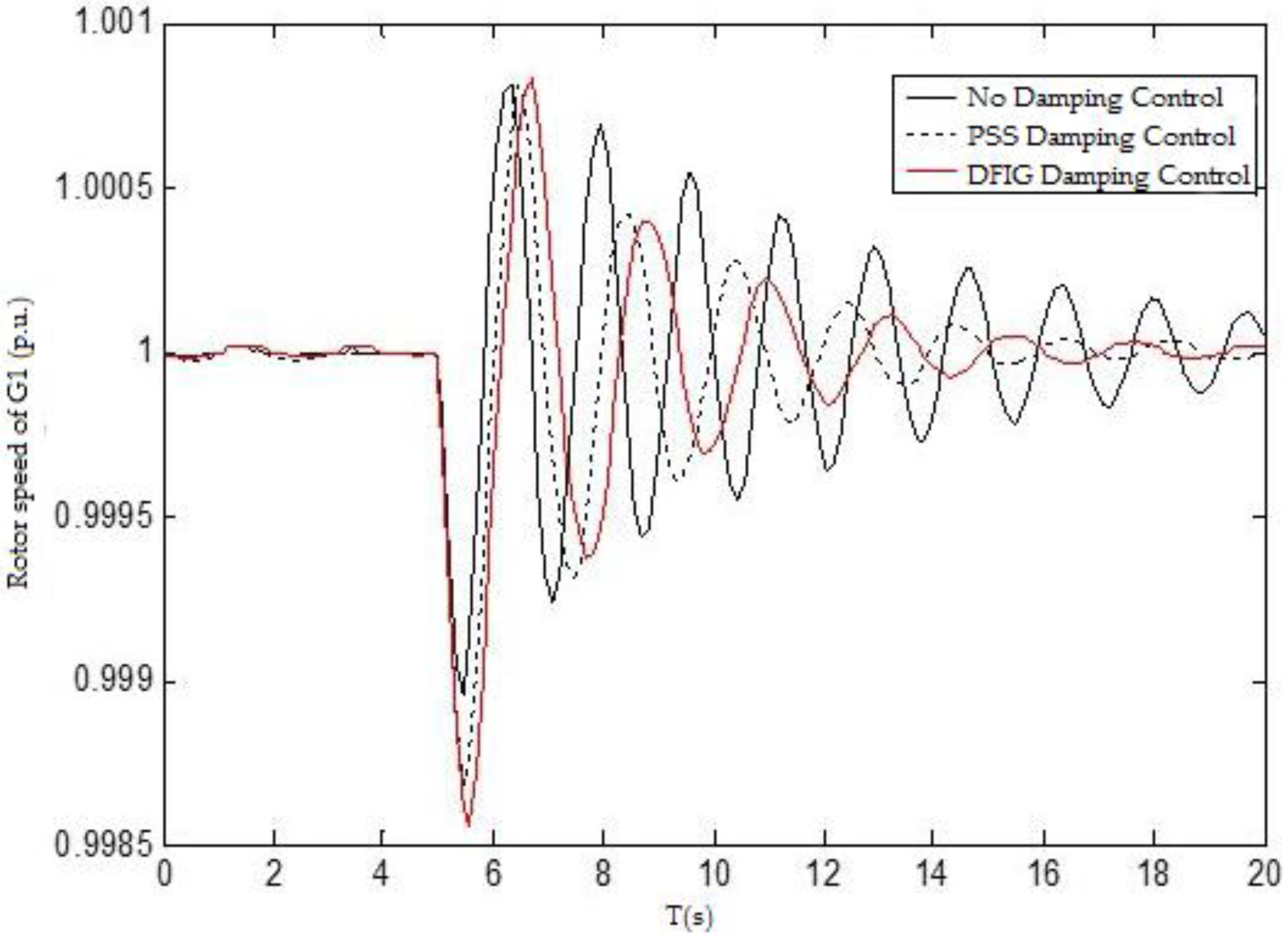
The rotor speed curves of the synchronous generator1 were under little perturbation in the case of PSS damping control, DFIG damping control, and no damping control as illustrated in
Figure 8 and
Table 3. It can be seen that the rotor speed fluctuates on a small scale under small perturbation, and oscillation settles down much faster when adopting damping control. Damping effect adding in synchronous machine and DFIG with the same active power output can achieve approximately the same effectiveness, proving the performance of supplementary damping control of DFIG.
The scenarios that the wind speed fluctuates in a considerable varying range are taken to validate the proposed method compared with the damping control method of the wind turbine proposed in [
19]. The comparative simulation results and the analysis in terms of time domain characteristics are shown in
Figure 9 and
Table 4.
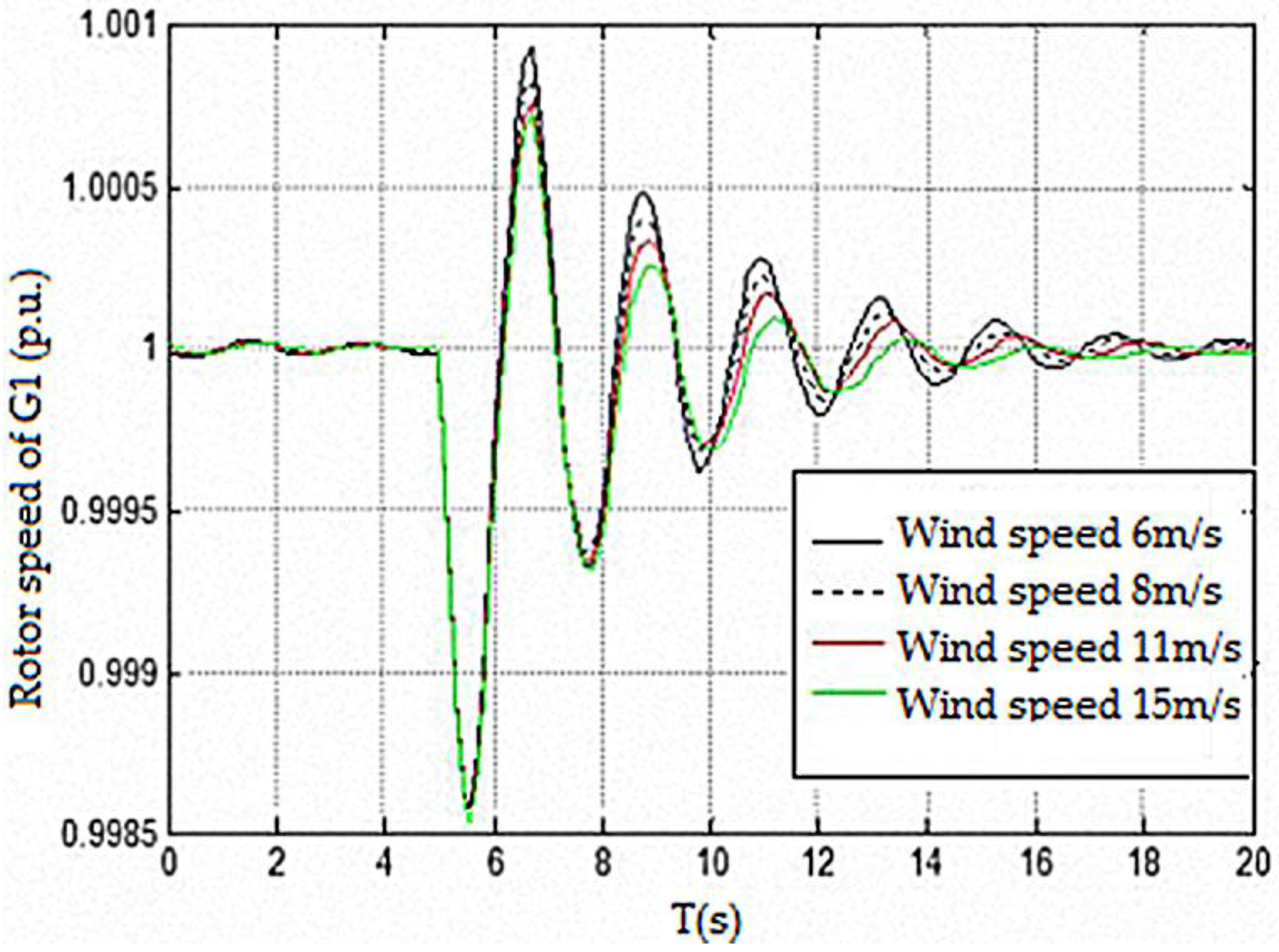
While the novel system oscillation resulted in little perturbation in the case of adding DFIG damping control and without PSS control is shown in
Figure 10. It is obvious that oscillation suppression effects of improved DFIG damping control tend to be less volatile in different wind speeds and is more practical.
By comparing the simulation results of the proposed method and the method proposed in [
19], it can be found that the control effects of both methods are satisfactory while in high wind speeds. From
Table 4 and
Table 5, it can be found that when wind speed is at its rated value, i.e., 15 m/s, the performance of the two control strategies are very close except that the first overshoot resulting from of the control strategy in [
19] is 2‰, while this index resulting from the control strategy proposed in this paper is only up to 1.5‰, which is slightly better. However, when wind speed decreases, the method proposed in this paper is still capable of maintaining a relatively good control effect, while the control effect of the compared method deteriorates. From
Table 4, it can be found that when wind speed decreases to 6 m/s, the second overshoot resulting from the control method in [
19] reaches 1.5‰, while this index resulting from the proposed method is below 1‰. Furthermore, in the follow-up periods, the damping process of oscillation is slow when utilizing the control method in [
19]. The fifth oscillation peak value is only attenuated to 25% of the first peak value under the control method proposed in [
19]. In contrast, by using the proposed method, this index can be attenuated below 5% of the first peak value. As a result, the consistency and the reliability of the damping control effect cannot be ensured unless the impact brought by various wind speeds, which can be eliminated by introducing a targeted negative feedback, is fully considered in the control strategy.
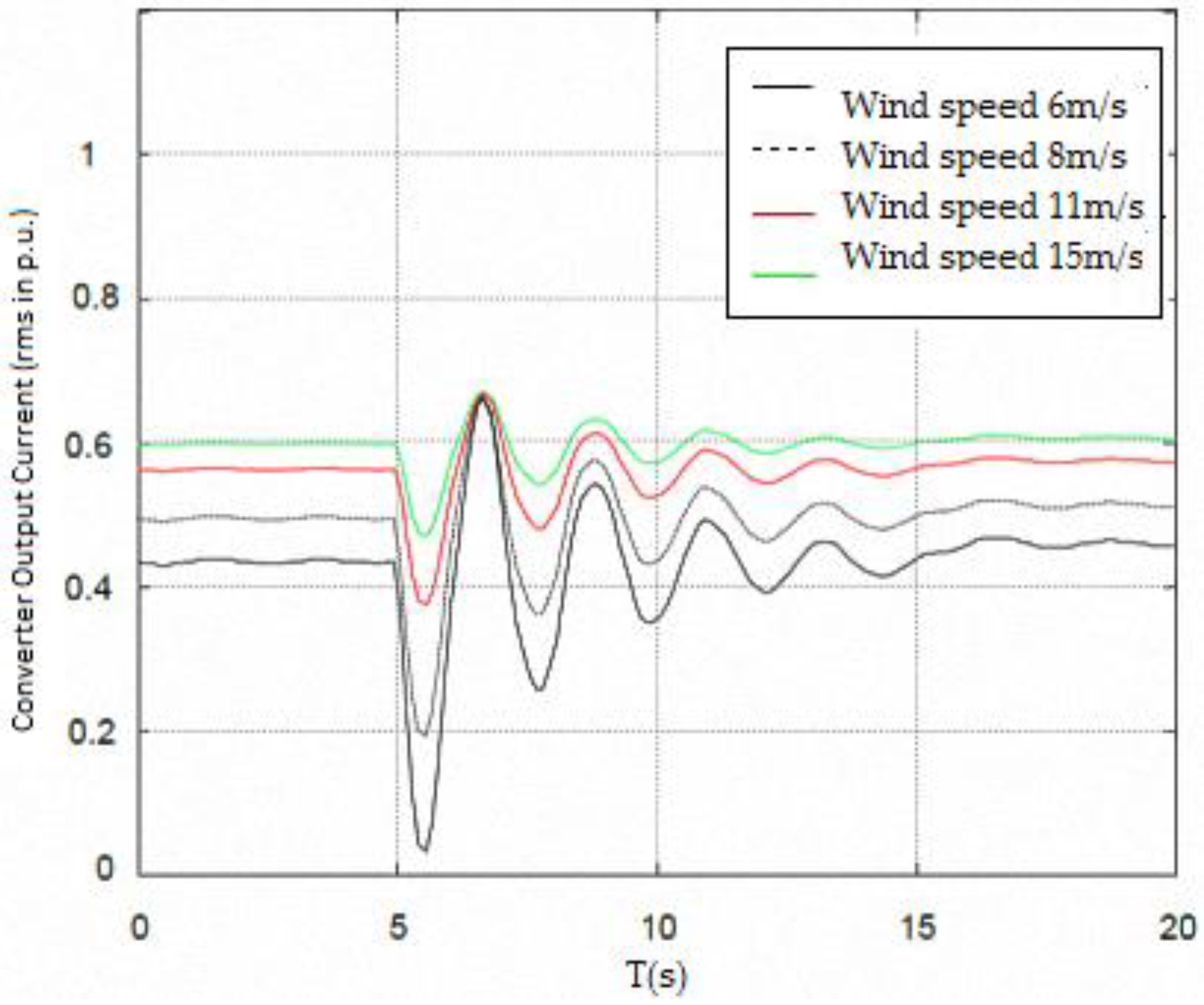
Converter rated capacity is determined by the maximum allowed slip power of the DFIG, usually 30%–40%, and most DFIGs nowadays have a converter capacity between 30% and 40% of the rated capacity of the DFIG. The output converter current of DFIG involved in damping control strategy and case study (
Figure 10) has been provided in
Figure 11. During our whole simulation study, the output current is always within the converter capacity limit.
The simulation results shows that, in any case, the maximum rise in the converter rms per-unit current is only 0.7, which is still within the operational thresholds. As long as the magnitude of converter output current does not exceed the threshold during the whole control process and under various wind speeds, it can be considered that the output converter current during damping action is within allowed limits. In this case, we consider our strategy effective and feasible.
6. Conclusions
In this paper, a supplementary control scheme for one of the most commonly used variable speed wind turbines DFIG is proposed to increase the damping of power system. Simultaneous tuning of parameters of these controllers is accomplished by using GA. The simulation results on a WSCC system demonstrate the effectiveness of the proposed control scheme in fixed wind speed.
Furthermore, In order to mitigate the problem of existing DFIG damping control strategies, that is, their effects are sensitive to wind speed and result in volatile system damping ratio, an improved damping control scheme based on the feedback regulation of wind turbine rotor speed is proposed to implement novel DFIG self-adaptive damping control under different wind speeds. Comparative simulation results show that the proposed strategy is able to maintain consistent and satisfactory control effects and ensure a stable power system damping ratio even with significant fluctuations of wind speed, which is the main advantage of the proposed method.
Acknowledgments
This work is supported by National Natural Science Foundation of China (NSFC) (51537003).
Author Contributions
This work was leaded by Aiguo Tan. The modeling process has been performed by Ran Lyu, Zhengtian Li, Long Peng and Muhammad Shoaib Khalid. Simulation and analysis of the results have been performed by Xiangning Lin and Jinwen Sun.
Conflicts of Interest
The authors declare no conflict of interest.
Symbol and Acronym
| DFIG | Doubly Fed Induction Generator |
| WT | Wind Turbine |
| PSS | Power System Stabilizer |
| PMSG | Permanent magnet Synchronous Generator |
| GA | Genetic Algorithm |
| MPPT | Maximum Power Point Tracking |
| LVRT | Low Voltage Ride Through |
| DAE | Differential Algebraic Equation |
| WSCC | Western Systems Coordinating Council |
| Pw | Input mechanical power of DFIG |
| Tm | Mechanical torque applied to the generator shaft |
| ωm | Mechanical angular velocity of DFIG rotor |
| p | Number of poles of the DFIG |
| Ps, Pr | Active power of DFIG stator and rotor, respectively |
| Qs, Qr | Reactive power of DFIG stator and rotor, respectively |
| s | Slip ratio of DFIG |
| f1 | Frequency of the DFIG stator current |
| f2 | Frequency of the DFIG rotor excitation current |
| xm | Excitation reactance of DFIG |
| ωb | angular velocity of DFIG rotor when frequency is 60 Hz |
References
- Gautam, D.; Vittal, V.; Harbour, T. Impact of increased penetration of dfig-based wind turbine generators on transient and small signal stability of power systems. IEEE Trans. Power Syst. 2009, 24, 1426–1434. [Google Scholar] [CrossRef]
- Yoon, M.; Yoon, Y.; Jang, G. A Study on maximum wind power penetration limit in island power system considering high-voltage direct current interconnections. Energies 2015, 8, 14244–14259. [Google Scholar] [CrossRef]
- Gómez-Lázaro, E.; Bueso, M.; Kessler, M.A. Probability density function characterization for aggregated large-scale wind power based on weibull mixtures. Energies 2016, 9, 91. [Google Scholar] [CrossRef]
- Chen, W.; Shi, L.; Yao, L.; Wang, L. Small signal stability analysis of the large-scale wind farm with DFIGs. Proc. CSEE 2010, 4, 63–70. [Google Scholar]
- Carlos, F.; Gallardo, Q.; Ledesma, L.P. Damping of inter-area mode oscillations with high penetration of the Power System in Wind. In Proceedings of the 34th Annual Conference of IEEE Industrial Electronics, IECON 2008, Orlando, FL, USA, 10–13 November 2008; pp. 2137–2142.
- Muljadi, E.; Butterfield, C.P.; Parsons, B.; Ellis, A. Effect of variable speed wind turbine generator on stability of a weak grid. IEEE Trans. Energy Convers. 2007, 22, 29–36. [Google Scholar] [CrossRef]
- Miao, Z.; Fan, L.; Osborn, D.; Yuvarajan, S. Control of DFIG-based wind generation to improve interarea oscillation damping. IEEE Trans. Energy Convers. 2009, 24, 415–422. [Google Scholar] [CrossRef]
- Tsourakis, G.; Nomikos, B.M.; Vournas, C.D. Effect of wind parks with doubly fed asynchronous generators on small-signal stability. Electr. Power Syst. Res. 2009, 79, 190–200. [Google Scholar] [CrossRef]
- Li, P.; Keung, P.K.; Ooi, B.T. Development and simulation of dynamic control strategies for wind farms. Renew. Power Gener. IET 2009, 3, 180–189. [Google Scholar] [CrossRef]
- Mishra, Y.; Mishra, S.; Tripathy, M.; Senroy, N.; Dong, Z.Y. Improving stability of a DFIG-based wind power system with tuned damping controller. IEEE Trans. Energy Convers. 2009, 24, 650–660. [Google Scholar] [CrossRef]
- Hughes, F.M.; Anaya-Lara, O.; Jenkins, N.; Strbac, G. A power system stabilizer for DFIG-based wind generation. IEEE Trans. Power Syst. 2006, 21, 763–772. [Google Scholar] [CrossRef]
- Ke, D.P.; Chung, C.Y.; Xue, Y. Controller design for DFIG-based wind power generation to damp interarea oscillation. In Proceedings of the IEEE 5th International Conference on Critical Infrastructure (CRIS), Beijing, China, 20–22 September 2010; pp. 1–6.
- Gautam, D.; Vittal, V.; Ayyanar, R.; Harbour, T. Supplementary control for damping power oscillations due to increased penetration of doubly fed induction generators in large power systems. In Proceedings of the IEEE Power Systems Conference and Exposition (PSCE), Phoenix, AZ, USA, 20–23 March 2011; pp. 1–6.
- Wang, Y.; Zhang, X.; Li, H.; Zhu, X. Damping control of PMSG-based wind turbines for power system oscillations. Trans. China Electrotech. Soc. 2012, 27, 162–171. [Google Scholar]
- Slootweg, J.G.; de Haan, S.W.H.; Polinder, H.; Kling, W.L. General model for representing variable speed wind turbines in power system dynamics simulations. IEEE Trans. Power Syst. 2003, 18, 144–151. [Google Scholar] [CrossRef]
- Muller, S.; Deicke, M.; de Doncker, R.W. Doubly fed induction generator systems for wind turbines. IEEE Ind. Appl. Mag. 2002, 8, 26–33. [Google Scholar] [CrossRef]
- Ilic, M.D.; Zaborszky, J. Dynamics and Control of Large Electric Power Systems; Wiley: New York, NY, USA, 2000. [Google Scholar]
- Jiang, P.; Yan, W.; Gu, W. PSS parameter optimization with genetic algorithm. In Proceedings of the Third International Conference on Electric Utility Deregulation and Restructuring and Power Technologies, DRPT 2008, Nanjing, China, 6–9 April 2008; pp. 900–903.
- Tossaporn, S.; Ngamroo, I. Hierarchical Co-ordinated wide area and local controls of DFIG wind turbine and PSS for robust power oscillation damping. IEEE Trans. Sustain. Energy 2016. [Google Scholar] [CrossRef]
© 2016 by the authors; licensee MDPI, Basel, Switzerland. This article is an open access article distributed under the terms and conditions of the Creative Commons Attribution (CC-BY) license (http://creativecommons.org/licenses/by/4.0/).


