1. Introduction
Fossil-fuel shortages and environmental concerns have strongly impacted the energy industries during the last decades. As one of the promising solutions to reduce the usage of the fossil fuel and carbon emissions, electric vehicles (EVs) are receiving much attention. Various infrastructures and charging standards for EVs have been presented considering different power levels as well as charging fields [
1]. Among them, the direct-current charging standard, which is defined to deliver high power and high current charging capability, normally requires an off-board charger. Traditionally, a unidirectional dc converter is able to satisfy the requirement of refreshing battery energy. Recently, various economical and technical issues about using EVs to support the power grid have been discussed [
2,
3]. In this sense, power has to be delivered between the utility and EVs to meet demand response and/or take advantage of time-of-use electricity rates. On the other hand, EVs should be able to act as a standalone backup power in emergency situations [
4,
5,
6]. Regarded as distributed energy resources, in this scenario EVs require an interface dc converter with both charging and discharging capabilities.
The dual active bridge (DAB) dc converter is a widely used circuit topology intended for bidirectional power flow, due to its soft-switching characteristic, high efficiency and low volume [
7]. The DAB converter is typically controlled by using so-called phase-shifted modulating method, in which two-level square waves with a designated phase shift are applied to the isolated transformer. In this sense, power flow and its direction can be controlled by the phase difference. However, this control method suffers from low conversion efficiency under light-load condition due to high conduction and switching losses. In order to improve the efficiency of the DAB converter, various modulating schemes have been presented. In [
8,
9], one of voltage pulses across on the transformer was replaced by a three-level pulse. In this sense, the DAB converter can operate in a wide-range soft-switching mode and its conduction loss can also be reduced by considering the reactive power of the converter [
10]. However, the required algorithm needs heavy computation to determine the operating point of the converter. The so-called triangular and trapezoidal modulations were proposed by imposing two three-level voltage pulses on the transformer [
11,
12]. By shaping the transformer current, both modulations can provide zero-current switching and reduce the circulating current under light-load conditions at the cost of voltage gain and power rating. Moreover, various optimization modulations have been proposed to reduce the peak current [
10] or reactive power [
13,
14], but they are not suitable for real-time applications due to their complexity.
In order for high-power applications, the bidirectional three-phase DAB (3ΦDAB) converter has been presented [
15]. The 3ΦDAB converter features higher power density compared with the single-phase DAB (1ΦDAB) converter. It is worth noting that the current frequency of the 3ΦDAB converter is three times of that of the 1ΦDAB converter. Thus the volume of the switching-ripple filters can be significantly reduced in the 3ΦDAB converter. However, similarly to 1ΦDAB converter, the 3ΦDAB converter with phase-shifted modulation still performs poor efficiency at low-power operation [
16,
17,
18,
19,
20,
21]. In [
20], a hybrid modulation strategy was proposed for the 3ΦDAB converter, including phase-shifted, triangular and trapezoidal modulations. The converter is able to operate at the highest efficiency with a changeable modulating scheme according to the operating point. This study was focused on the estimations and analysis of the various modulations, but no information was provided on how to determine optimizing modulation, which may be very difficult in real-time implementation. Furthermore, the considered triangular modulation may substantially increase the complexity of the modulation scheme.
The authors have presented the 3ΦDAB converter with hybrid modulation in previous research [
21]. The converter is able to switch its modulation between phase-shifted and trapezoidal modes autonomously to maintain efficiency even in the light-load condition. In this paper, we further focused on theoretical analysis of the mode transition based on loss analysis of the circuit. The condition of when the modulation modes switch is pre-determined based on efficiency analysis. Design considerations of the modulation are also proposed and the corresponding suggested control progress with flowchart for hybrid modulation is also provided. A lab-scale platform consisting of a 1.2 kW 3ΦDAB converter with a 48V/20Ah LiFePO
4 battery was established to verify the proposed method.
3. Hybrid Modulation Design
In this paper, a hybrid modulating strategy was proposed to allow the converter to be able to autonomously switch between phase-shift and trapezoidal modes according to output current. The turning point for mode transition is pre-determined based on efficiency analysis, which includes device loss and magnetic loss. The former part consists of both conduction and switching losses. The latter one is estimated based on the datasheet of core material.
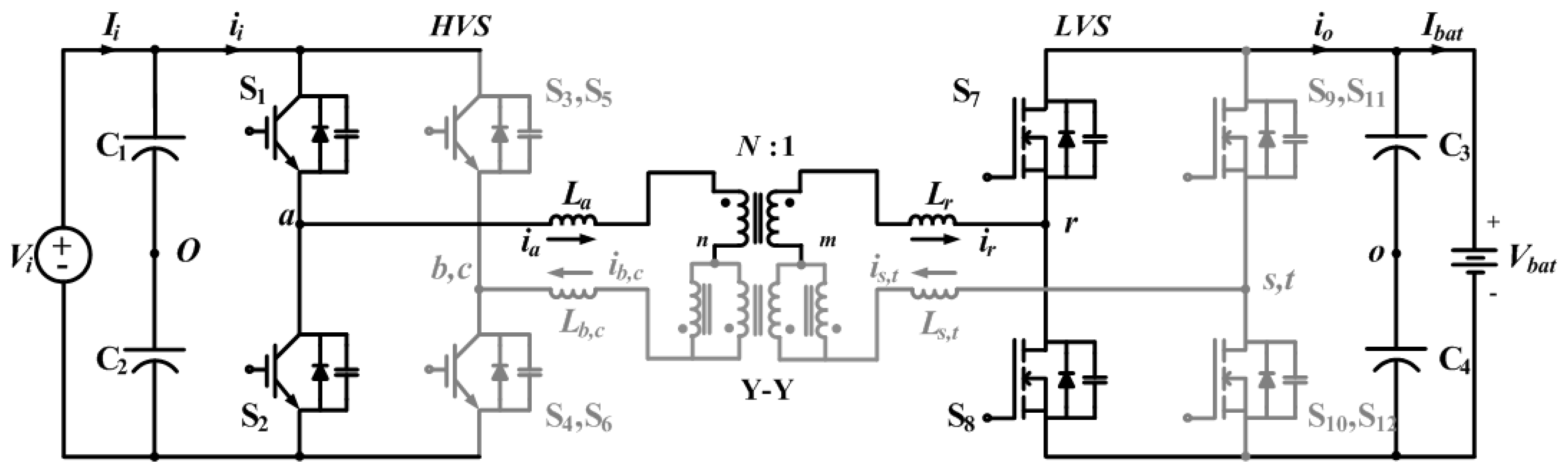
Table 1 shows the circuit parameters used in this paper. The primary-side and secondary-side switches are IGBTs (IXGK60N60BsD1, 600 V, 75 A, IXYS Co., Ltd., Milpitas, CA, USA) and MOSFETs (IXFK120N20P, 200 V, 120 A, IXYS Co., Ltd., Milpitas, CA, USA), respectively.
3.1. Loss and Efficiency
For EV application, the charging operation with adjustable charging current according to the operator is the main focus. That is why we design the converter for high efficiency from light load to heavy load. The power flow of the proposed DAB circuit can be controlled between the primary and secondary sides, so the theoretical analysis has addressed dual operation for both charging and discharging behavior.
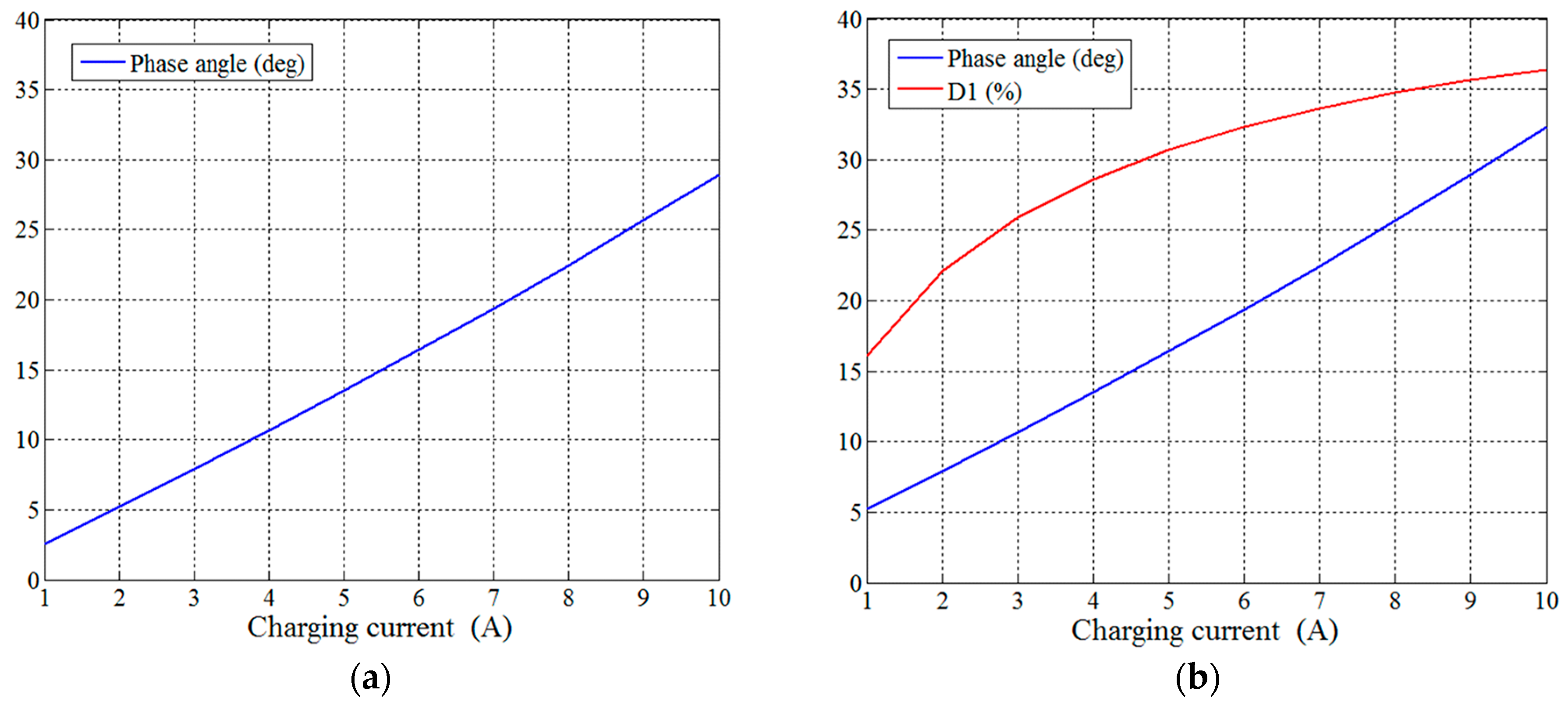
Figure 4 shows phase-shifted angle and duty ratio with respect to output current for both modulating modes, which were calculated by adjusting phase-shifted angle. Based on the modulation parameters in
Figure 4, converter loss and its efficiency can be derived.
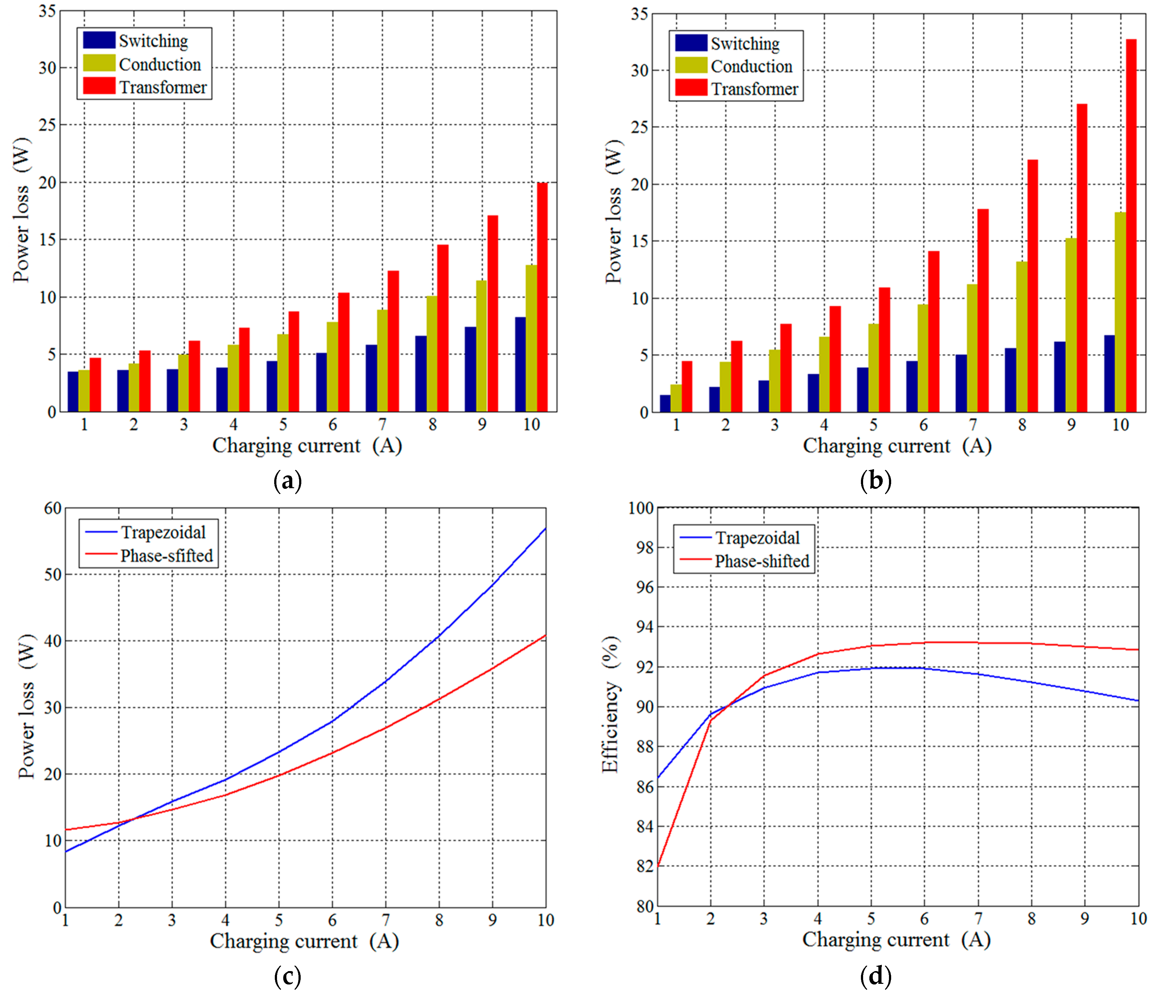
The 50% duty ratio makes phase-shifted modulation less loss in high current operation in
Figure 5a. However, the phase-shifted modulation suffers from high switching loss in low current range due to loss of ZVS. On the other hand, the trapezoidal modulation benefits in low current range due to reduced circulating current in
Figure 5b, but the conduction loss significantly increases with increasing output current. Therefore, the crossover point of the efficiency curves in
Figure 5d is located around 2 A, which is a preferred selection of the mode-switching current
Imode. Despite the power loss equations and simulation results, we still use the trial-and-error method to locate the crossover point of the efficiency curves and select 2 A as the mode-switching current
Imode in the experiment. The efficiency curves and the preferred mode-switching current
Imode is measured and verified in the experimental results in a later section.
Because the experimental platform is over-designed for protection, the operation range where the trapezoidal modulation provides better efficiency is limited. If the 600V/40A IGBTs and 200V/50A MOSFETs are chosen, the crossover point will up to 3 A but the platforms will have higher risk.
3.2. Control Scheme
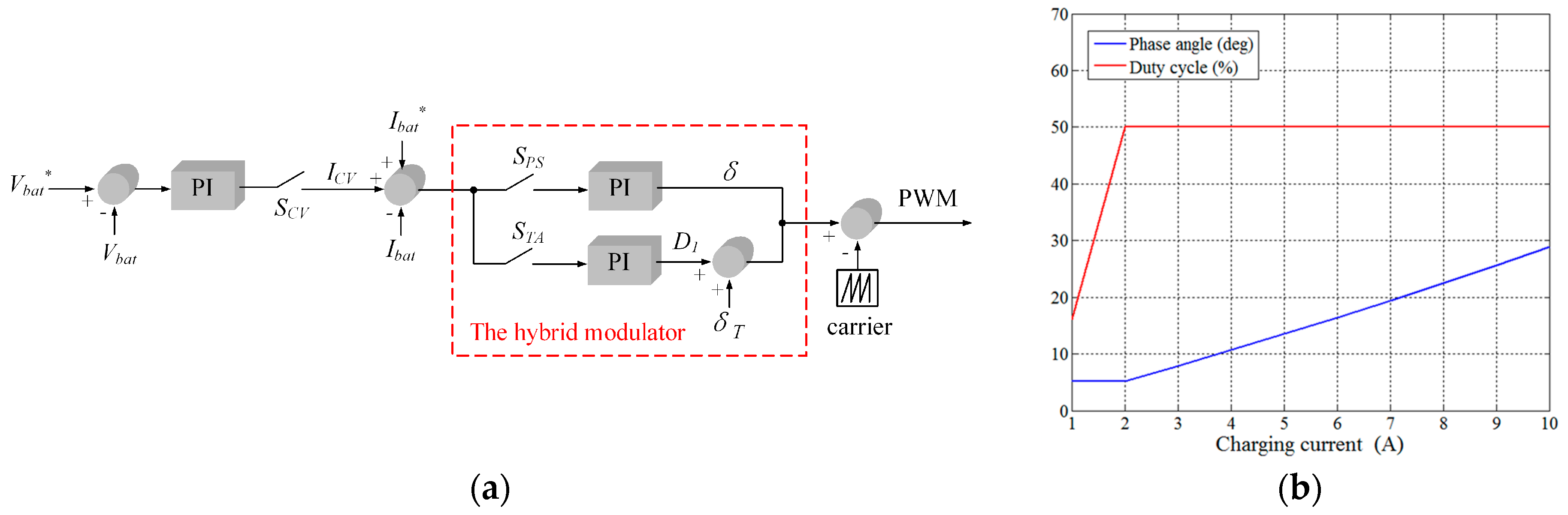
Figure 6a shows the proposed control block diagram, including battery charging scheme and hybrid modulator. The logical switches shown are to explain control flow only. Both constant-current (CC) and constant-voltage (CV) modes are designed in the battery charging algorithm. In the CC mode, logic switch
SCV is set at off-state so that the modulator input is simply determined by current command
Icomd only. On the other hand, battery voltage
Vbat is required for CV operation. As shown, logic switch
SCV is changed to on-state to produce the modified current I
CV that is added to
Icomd for the hybrid modulator.
Based on the pre-determined current turning-point
Imode, a suitable modulation, phase-shifted or trapezoidal mode, is selected to generate a phase-shifted angle and/or duty ratio. As shown, in phase-shifted modulation, the logic switch
SPS is turned on to allow a PI controller generating phase angle command δ according to the current command
Icomd. On the other hand, duty ratio command
D1 can be produced by turning on
STA for the trapezoidal mode. The required phase angle δ
T is the phase-shifted angle at current turning-point
Imode.
Figure 6b shows the mode transition of the hybrid modulator, where
Imode is set as 2 A. As shown, δ and
D1 are controllable variables for the current command larger and less than 2 A, respectively.
There are two variables, duty cycle
D1 and phase angle δ
T in trapezoidal modulation. When switching from phase-shift to trapezoidal modulation, the phase angle δ generated by phase-shift modulation is sent to trapezoidal modulation as a fixed variable. During the trapezoidal modulation, the phase angle won’t be changed by the PI because the
SPS in
Figure 6a is off. This hybrid modulator design reduces the bouncing problem between modulations.
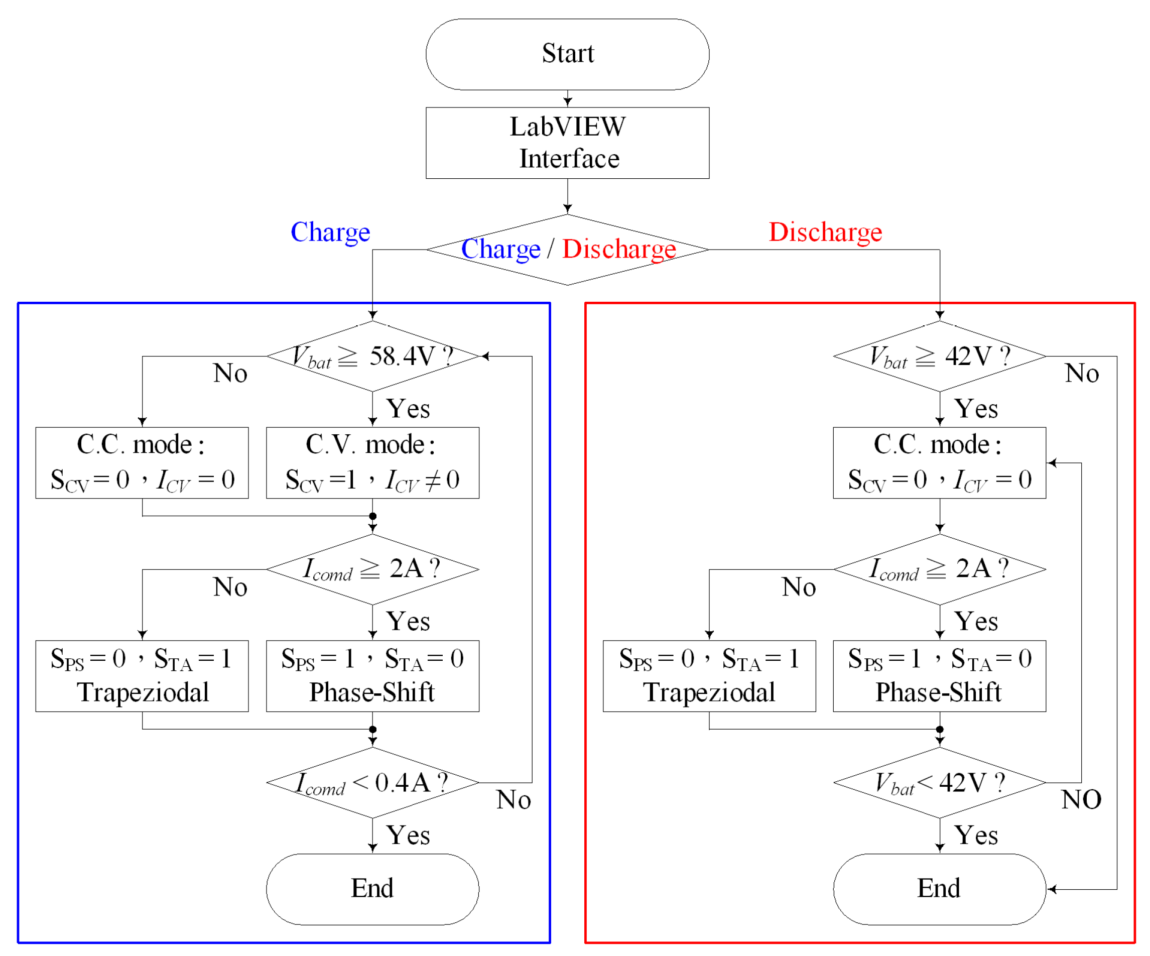
Figure 7 shows the flowchart of the proposed control scheme. After obtaining a battery charging or discharging command, the converter determines its operation based on battery voltage. In charging case, CC mode is normally chosen and the hybrid modulator determines the modulating strategy according to
Imode. At the end of charging, CV is started instead to decrease charging current. The charging process is ended as the charging current is less than 0.4 A. For discharging requirement, only current command is needed. A low-voltage limitation 42 V is considered in this case for preventing battery from over-discharging.
4. Experimental Results
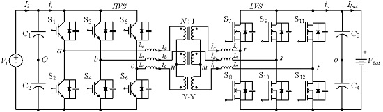
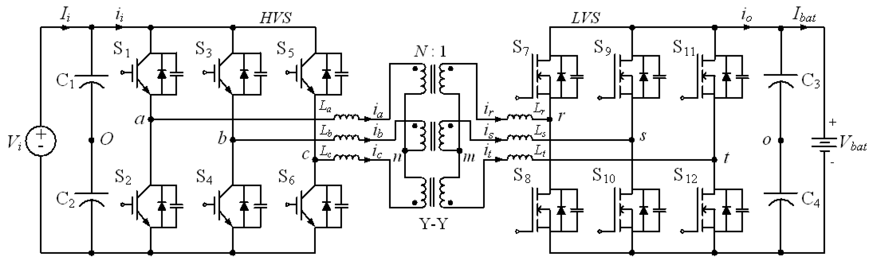
An experimental prototype is established to measure efficiency of the three-phase DAB converter with the hybrid modulation, and experimental parameters are shown in
Table 1. Considering power rating, voltage rating and over-design for protection, the converter circuit use IGBTs (IXGK60N60BsD1, 600 V, 75 A) as primary-side switches and MOSFETs (IXFK120N20P, 200 V, 120 A) as secondary-side switches. A DC power supply is applied to theprimary side while the LiFePO
4 battery (TY-D 20-48, 20AH, Ty Dynamic Co., Ltd., New Taipei City, Taiwan) is applied to the secondary side. A three-phase transformer is composed by three single-phase ferrite-core transformers (ferrite core, EE55-28-21-MB3, New Favor Industry Co., Ltd., Taipei, Taiwan). The leakage inductance of the transformer is referred to the high-voltage side. The control strategy of the converter is accomplished via usage of a digital signal processors (DSPs, TMS320C28335, Texas Instruments, Dallas, TX, USA).
4.1. Steady State
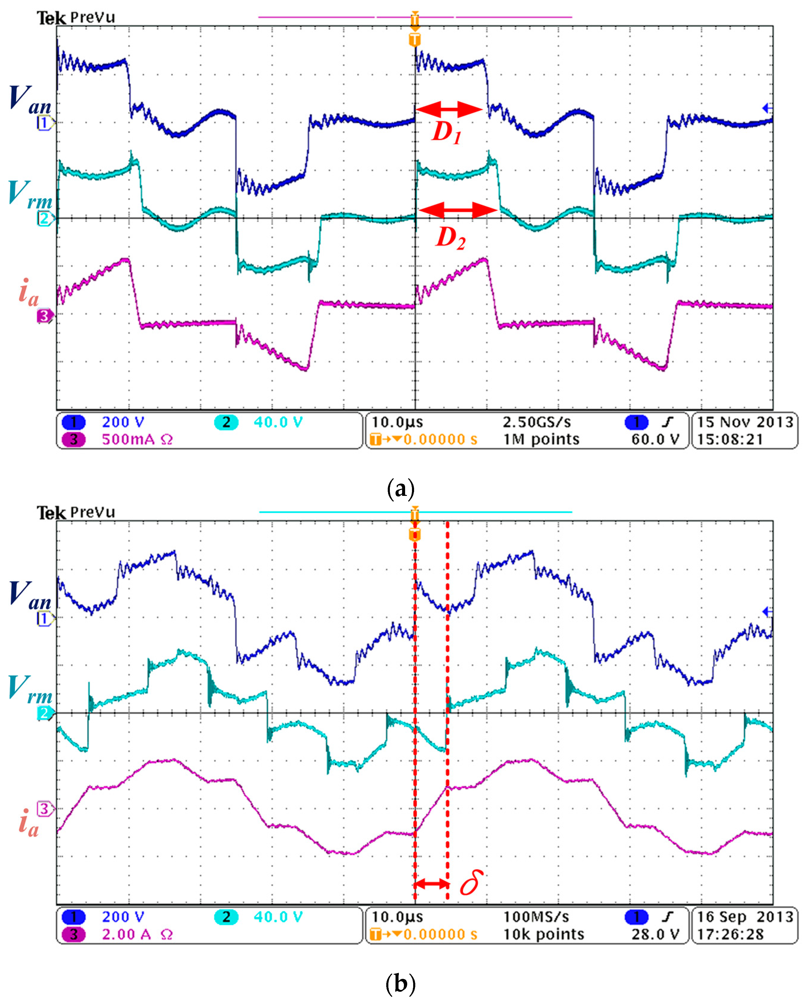
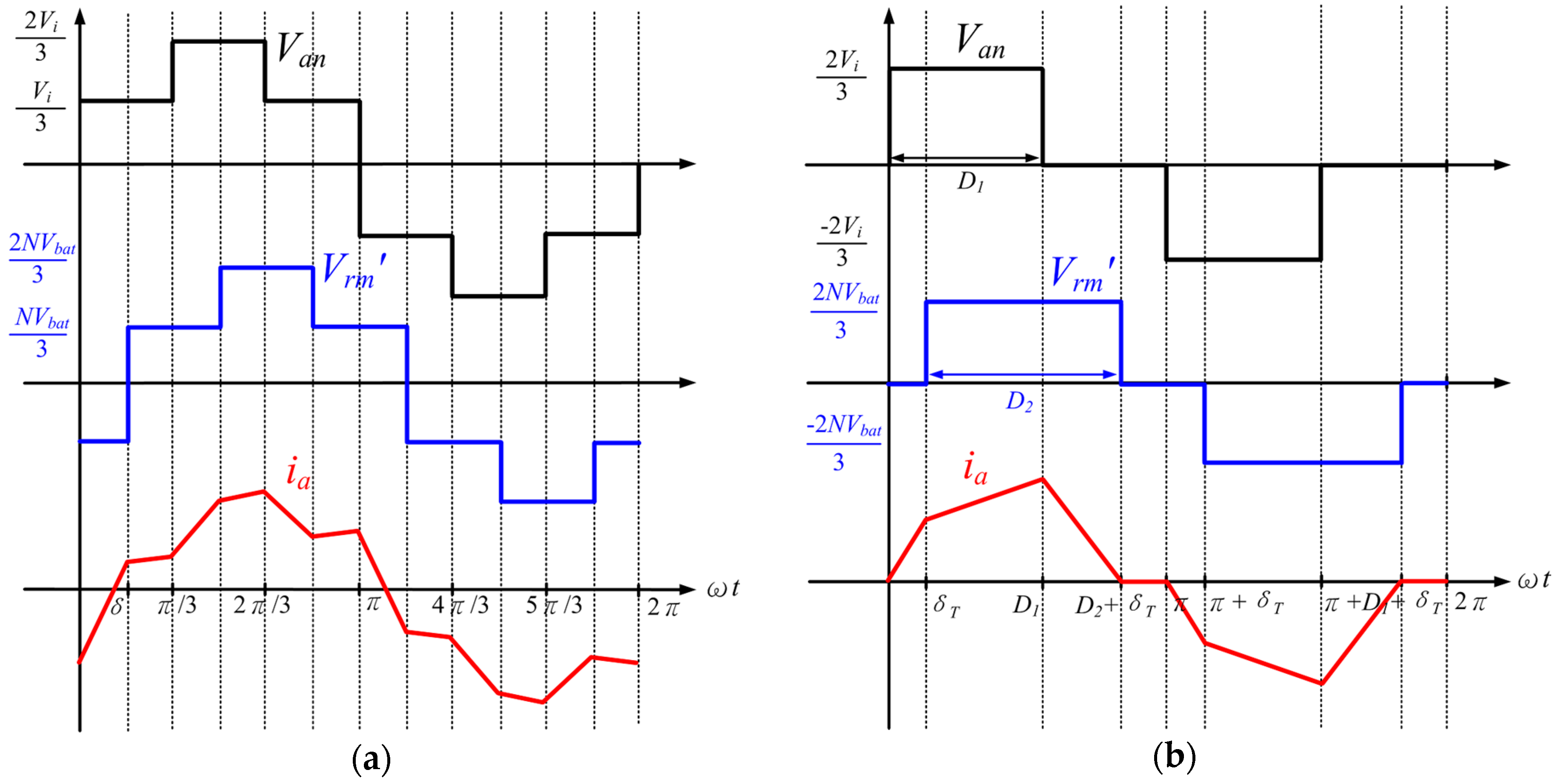
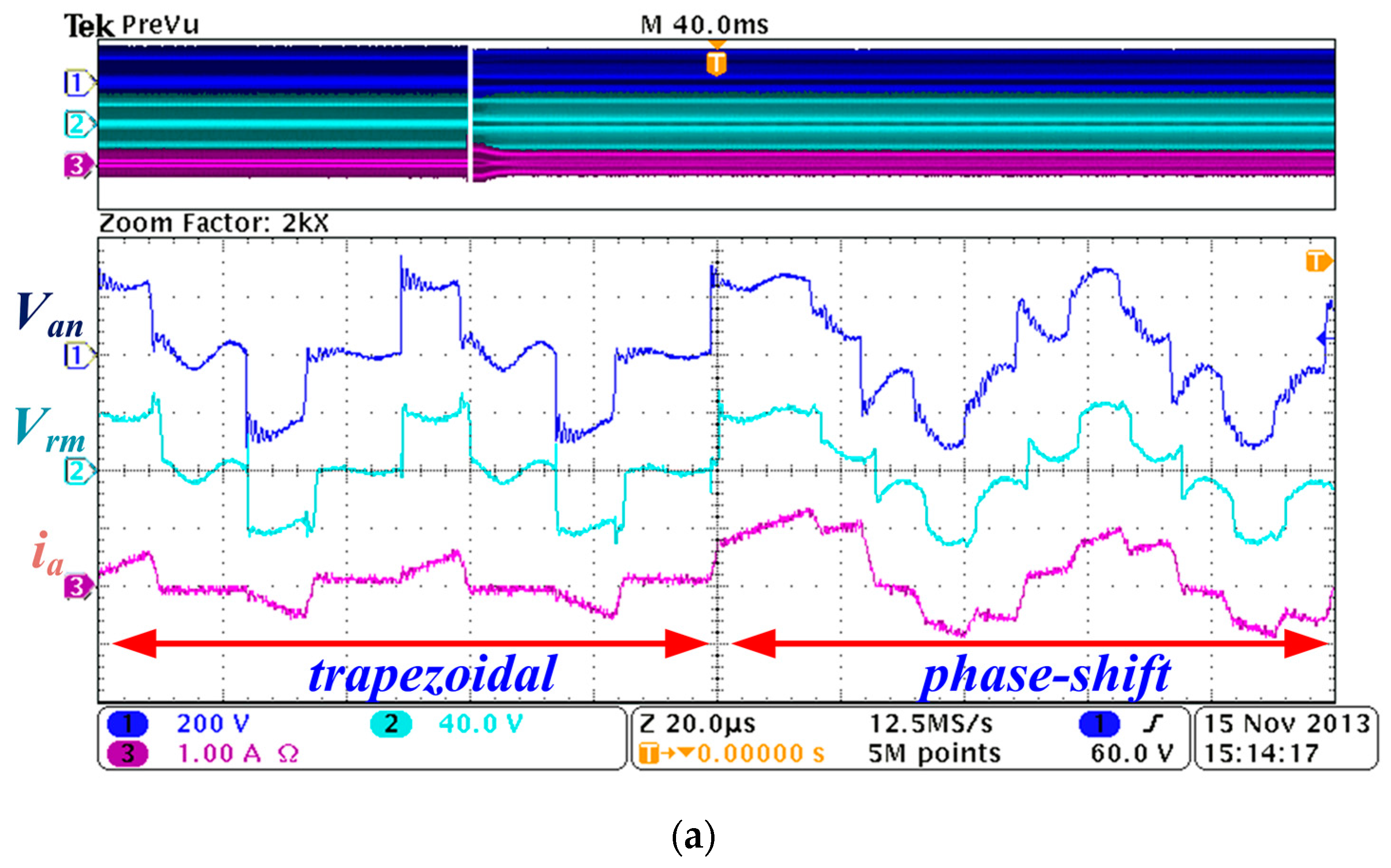
Figure 8a shows
Van,
Vrm,
ia waveforms when the converter is operated at
IB* = 1 A. Obviously, trapezoidal modulation is enabled with parameters
D1 = 23.5% (11.75 μs),
D2 = 25.86% (11.75 μs) and δ
T = 5.2° (0.72 μs). Note that the transformer current
ia is approximately equal to 0.1 A due to dead time.
Figure 8b shows key waveforms in phase-shifted modulation at
IB* = 10 A, in which the phase angle δ is 30°.
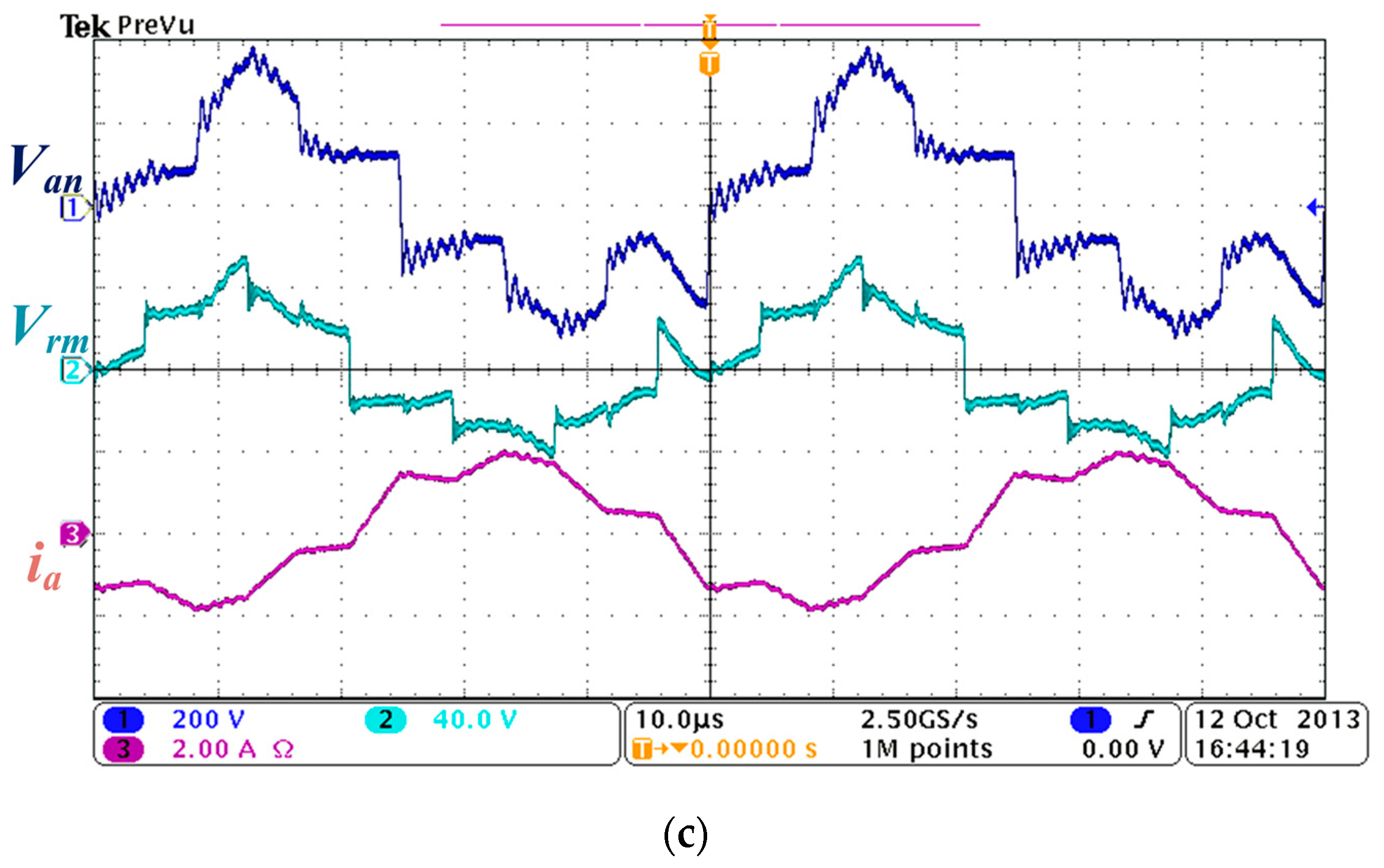
Figure 8c shows the waveforms also in phase-shifted modulation but with
IB* = −10 A discharging current.
4.2. Transient Behaviour
Figure 9a illustrates the transient waveform when the charging current command
Ibat* increases from 1 to 4 A. As expected, the modulation is successfully switched from trapezoidal mode to phase-shifted mode.
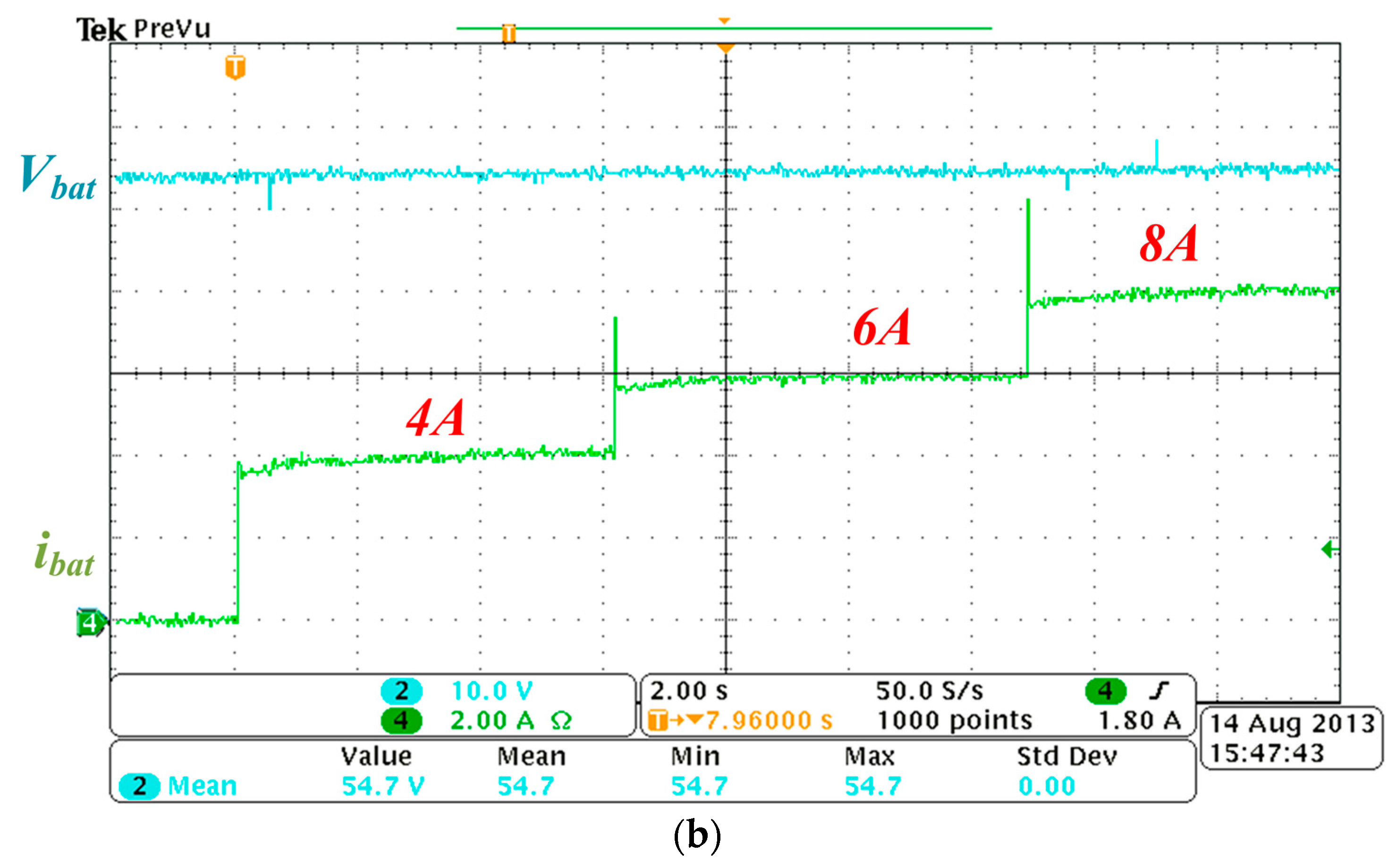
Figure 9b shows the transient behavior when the charging current command
Ibat* is increased from 0 to 4, 6 and 8 A, respectively. As shown, the charging current
Ibat can is able to follow the current command
Ibat*.
In normal operation, the current command
Icomd is tuned slowly in constant-voltage mode, so the PI controller in the hybrid modulator can be designed for fast-tracking ability with hard-to-notice overshoot transient. Since the transient experiments are extreme case of current-command-
Icomd adjustment, the current spikes in
Figure 9b actually is the overshoot expressed in terms of 2 s/div, which is induced by the fast-tracking PI controller.
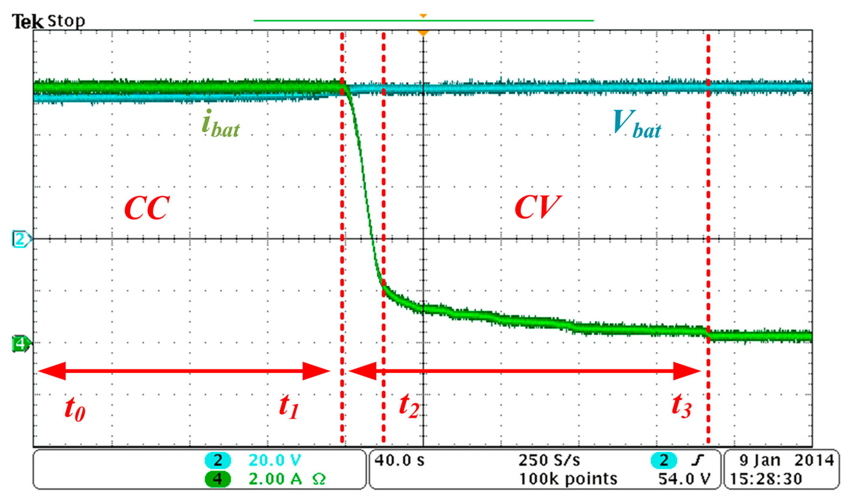
4.3. CV Operation
Figure 10 shows battery voltage
Vbat and battery current when the operation of the converter changes from CC mode to CV mode. The converter runs in CC mode at
Ibat* = 10 A during
t0–
t1 period, which is modulated by the phase-shifted scheme. When the battery voltage is equal to 58.4 V at
t1, the charging mode switches to CV mode. During the CV mode, the converter still operates in phase-shifted modulation during
t1–
t2 period since the charging current
Ibat is larger than
Imode = 2 A. When
Ibat is less than 2 A, the converter changes its modulation to the trapezoidal mode during the
t2–
t3 period. After
Ibat is smaller than 0.4 A at
t3, the battery charging is terminated.
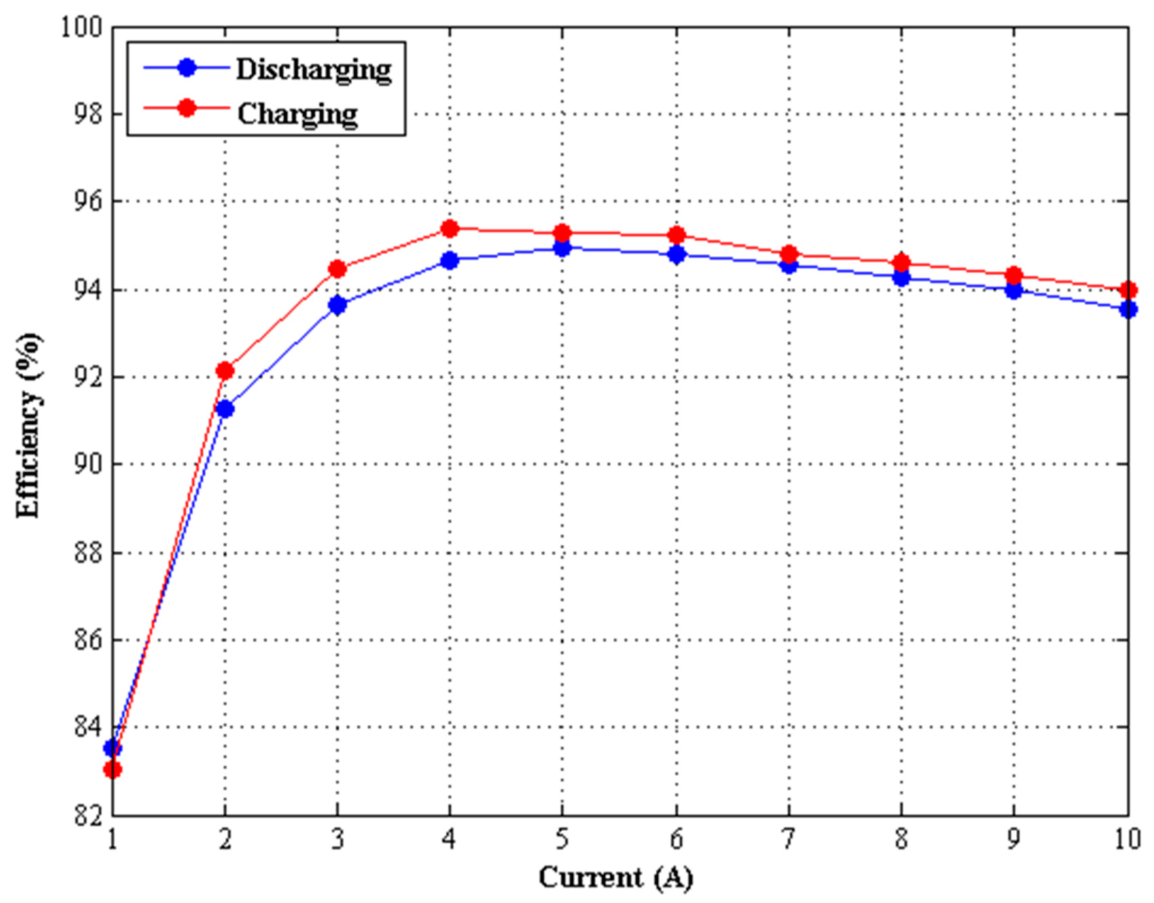
4.4. Efficiency
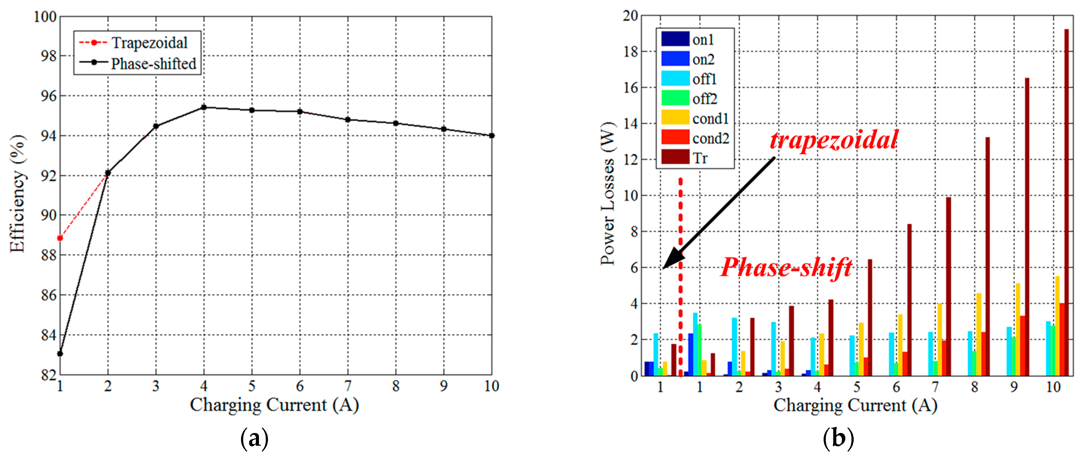
The measured efficiency curve is shown in
Figure 11a. The efficiency is improved as the charging current less than 2 A. For example, the efficiency is increased from 83.04% to 88.66% at
Imode = 1 A.
Figure 11b gives detailed measurements of the power loss in phase-shifted mode and the result in the trapezoidal mode for light load condition. Label on1 and on2 stand for the turn-on loss of primary- and secondary-side switches, respectively; label off1 and off2 stand for the turn-off loss of primary- and secondary-side switches, respectively; the label cond1 and cond2 stand for the conduction loss of primary- and secondary-side switches, respectively; label Tr stands for the transformer loss. Transformer loss occupies over 60% loss, which might be improved by using low core loss material. This results verifies the availability of hybrid method.
Figure 12 shows the charging and discharging efficiency curves with phase-shift modulation, where the overall efficiency during discharging operation is 0.5% to 1% lower than the charging efficiency. The voltage gain d becomes reciprocal and decreases when discharging from low voltage to high voltage. According to power transfer Equations (1) and (2), the phase-shift angle δ increases based on the decreased voltage gain d while maintaining the same transfer power, so the peaks of transfer three phase current causally raises which aggravate the transfer loss and reduce the efficiency slightly.


