
Global Maximum Power Point Tracking (MPPT) of a Photovoltaic Module Array Constructed through Improved Teaching-Learning-Based Optimization


Abstract
:1. Introduction
2. Fault and Shading Characteristics of PV Module Arrays
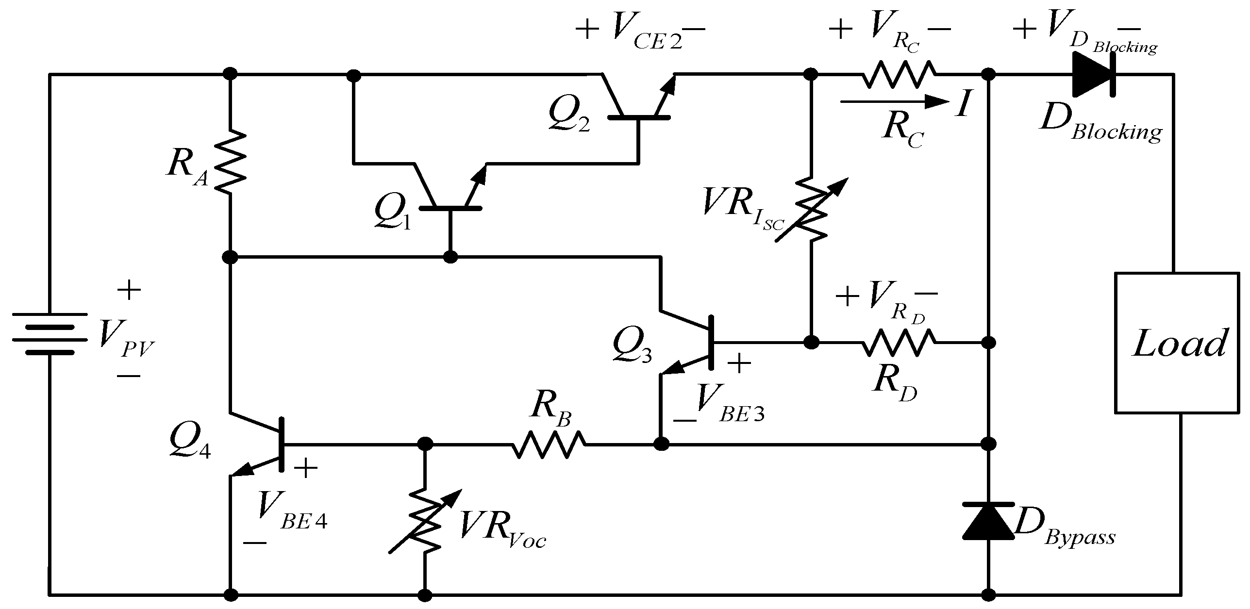
2.1. PV Module Simulator Circuit
2.2. PV Module Array Fault and Shading Characteristics Analysis
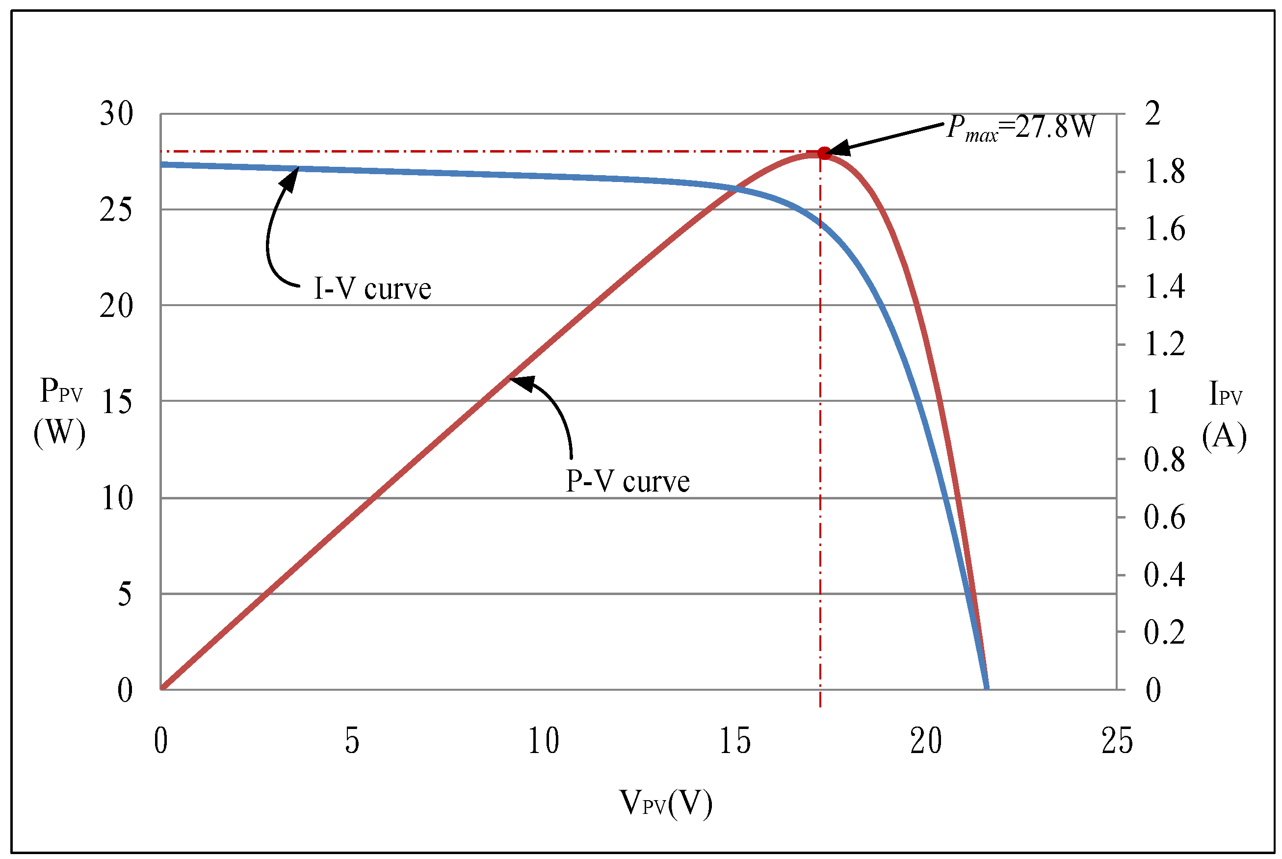
2.2.1. PV Module Array Characteristics without Faults or Shading
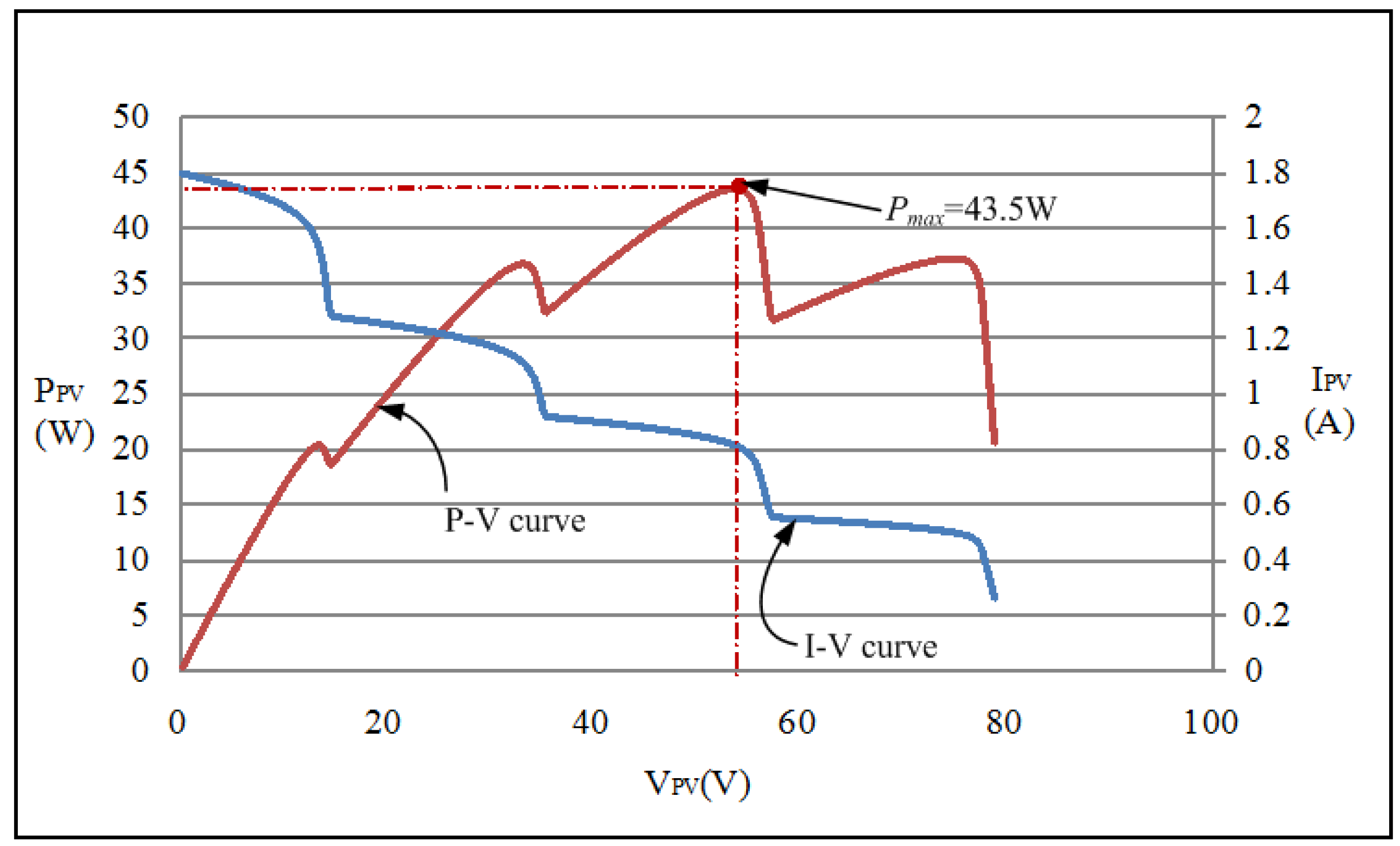
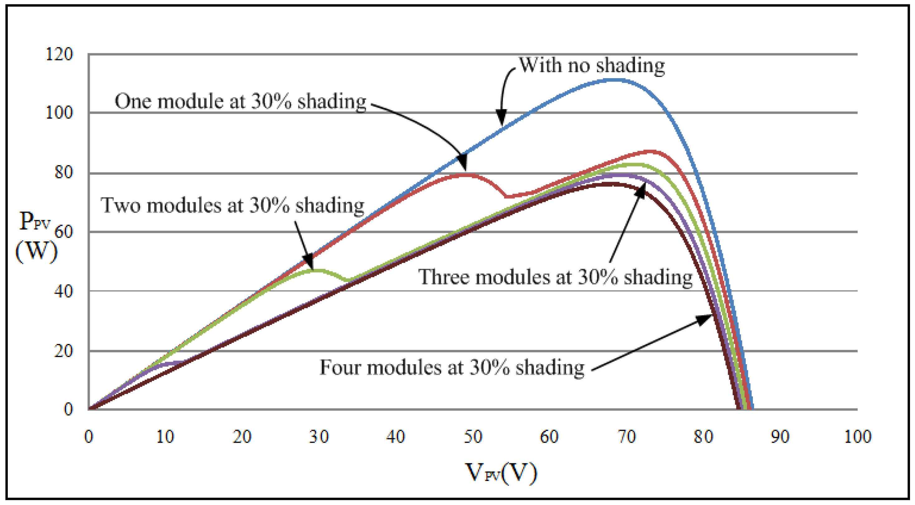
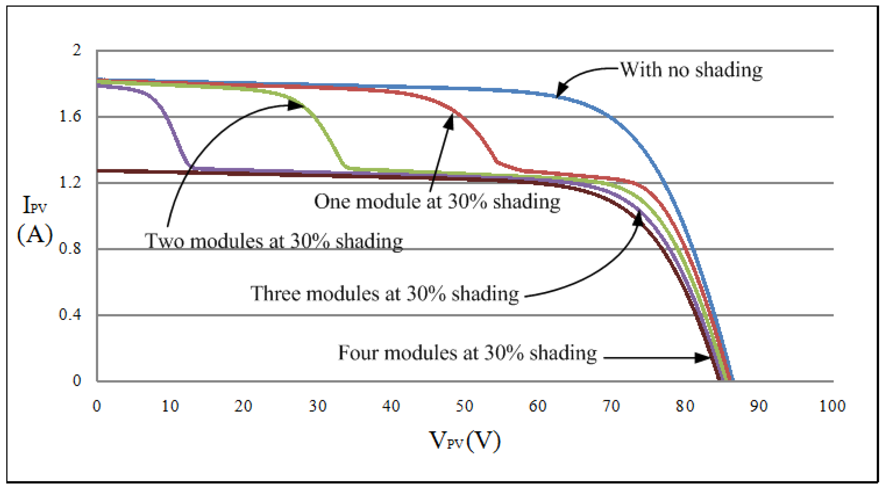
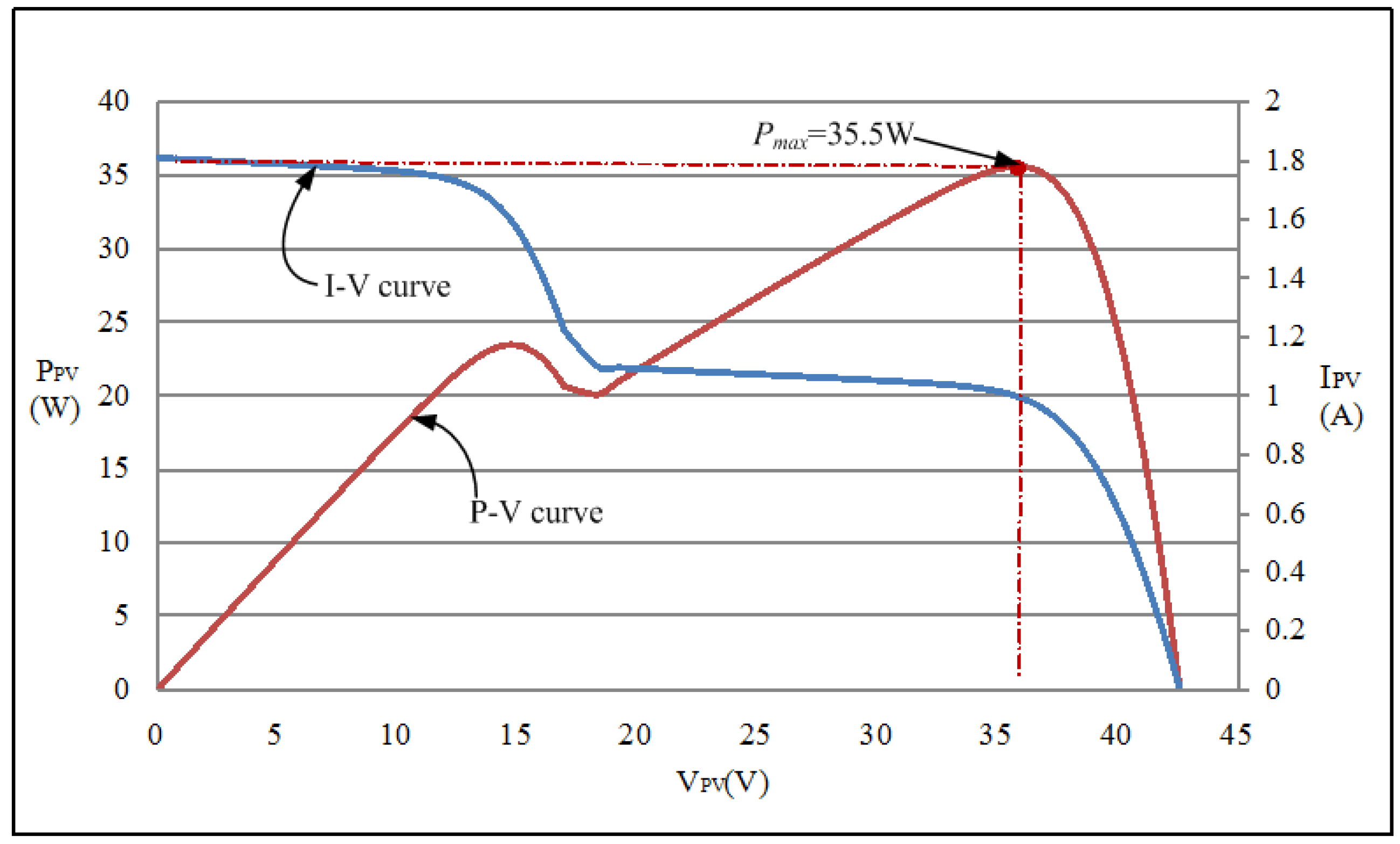
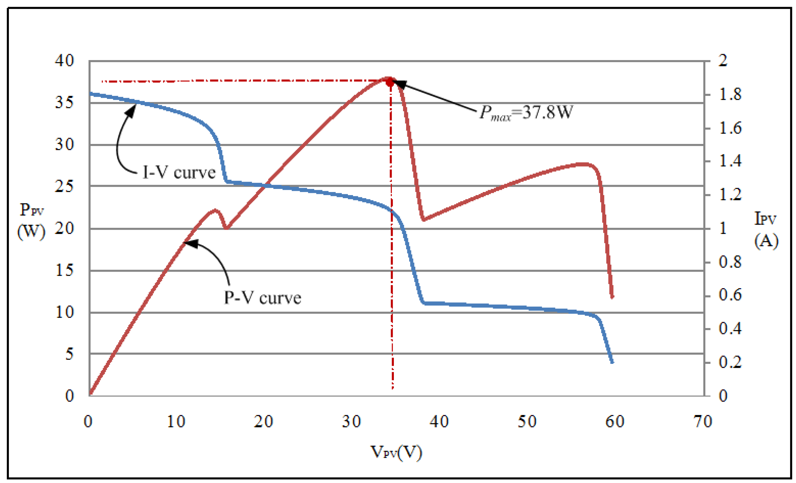
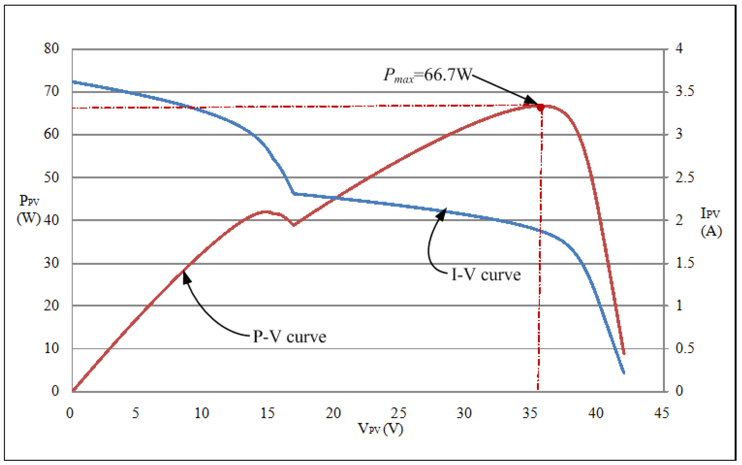
2.2.2. PV Module Array Characteristics with Faults or Shading
3. Teaching-Learning-Based Optimization (TLBO) Method
3.1. Conventional TLBO Method
- Step 1:
- Set the values for the number of students Np, subjects m, and iterations E.
- Step 2:
- Initialize a class S and define the following parameters:
- (a)
- Random student:
- (b)
- Random subject:
- (c)
- Target grade of student k in subject j:
- Step 3:
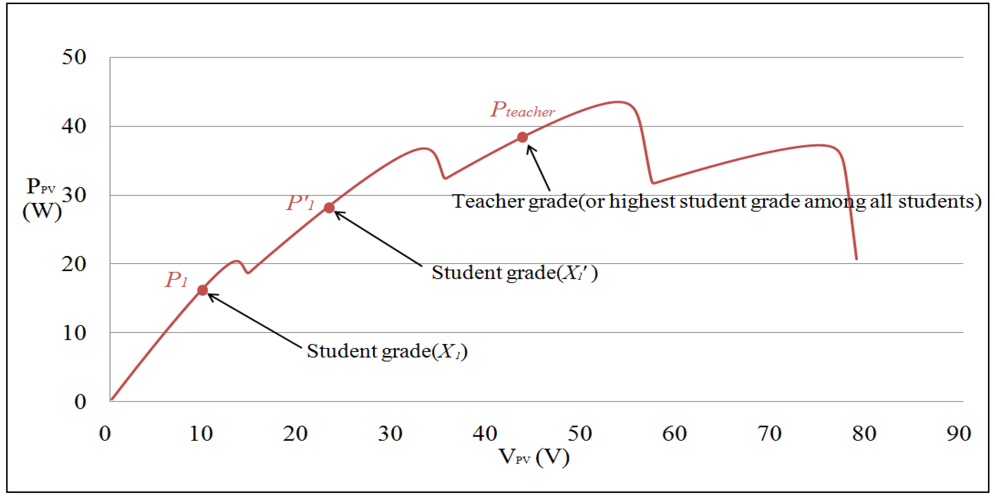
- In the teaching phase, learning step ri, teaching factor TF, and students with the highest grades Xj,k_best are given. The mean of a class is calculated according to Equation (3) and substituted into Equation (4) to determine the student mean difference value. Finally, student grades are updated according to Equation (5) to identify the new target grade for each student in the teaching phase:
- Step 4:
- In the learning phase, we assume that two random students XP and XQ participate in mutual learning, in which the student with the lower grade learns from the one with a higher grade. Adjustments were made using Equation (6):
- Step 5:
- Repeat steps 3 and 4 until the iteration is completed.
- Number of students (Np): Total number of participating students.
- Number of iterations (E): Number of teaching and learning phases that the students experience.
- Subject grade (Xj,k): Grade of student k in subject j. Five subjects were used in the present study.
- Class mean (M): Mean grade of the class.
- Teaching step (ri): Parameter for diversifying the student mean difference with a random value between 0 and 1.
- Teaching factor (TF): Teachers’ ability to teach the students. The parameter randomly generates a value of 1 or 2.
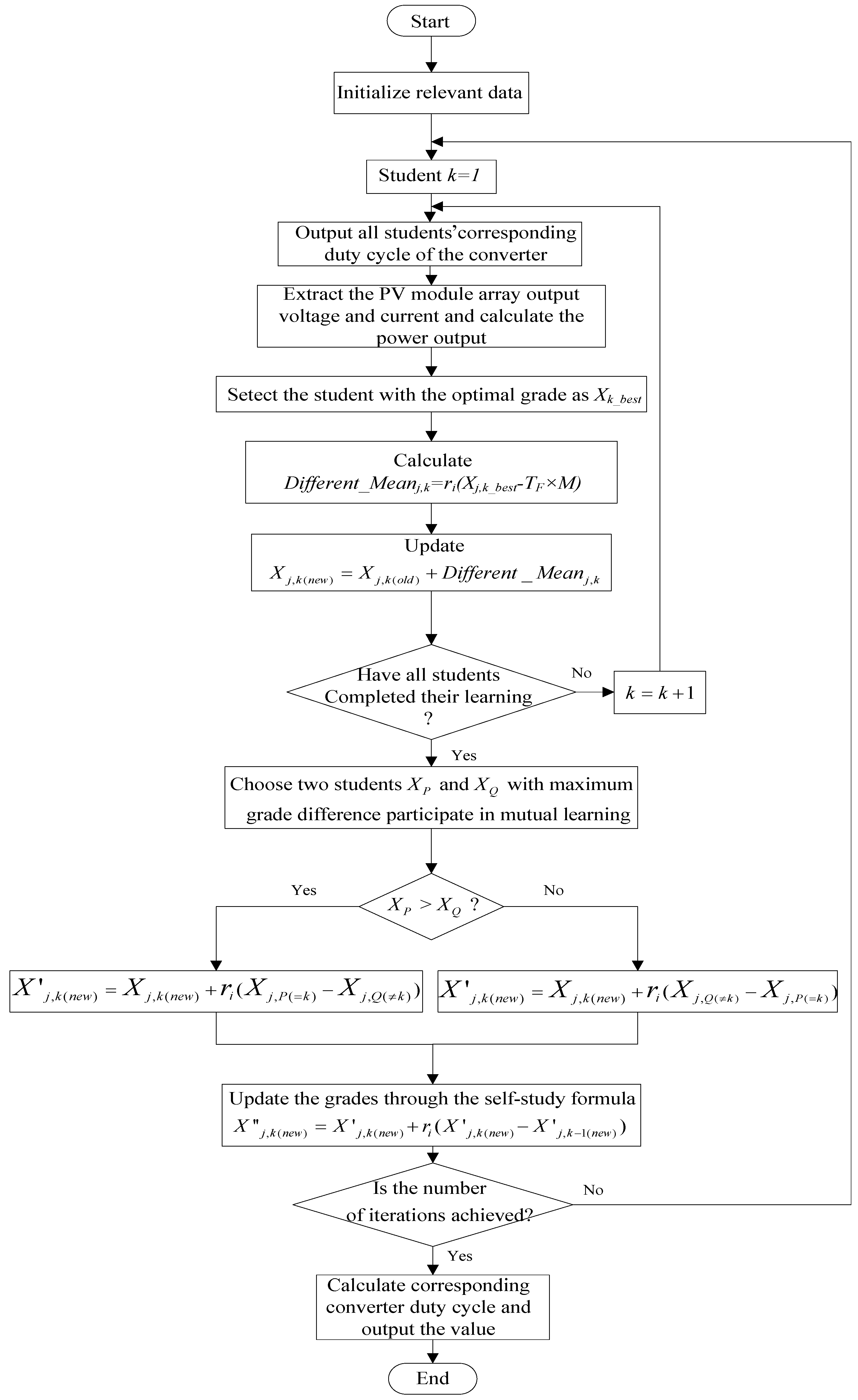
3.2. The Proposed I-TLBO Method
- Modification 1: The teaching factors TF were modified to be automatically adjustable according to the students’ learning capacity. The adjustment method is expressed in Equation (7):
- Modification 2: In the learning phase, a student selects another student who could benefit their learning the most in order to boost their learning effectiveness.
- Modification 3: A self-study process was incorporated into the learning phase to enable each student to adjust their self-learning according to their previous experience, as expressed in Equation (8):
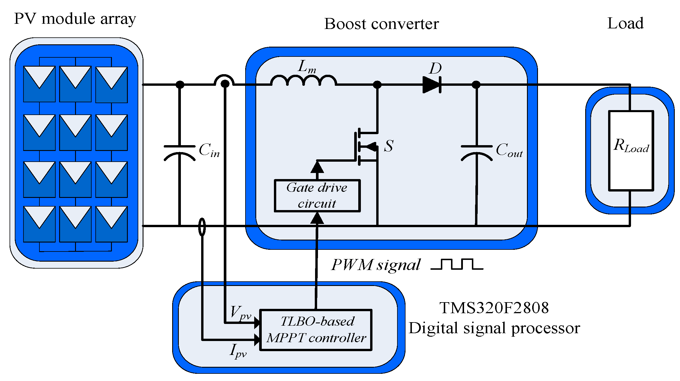
3.3. MPP Tracker
4. Measurement Results
4.1. PV Module Array Characteristics under Different Operating Situations
4.2. MPPT Measurement of PV Module Arrays
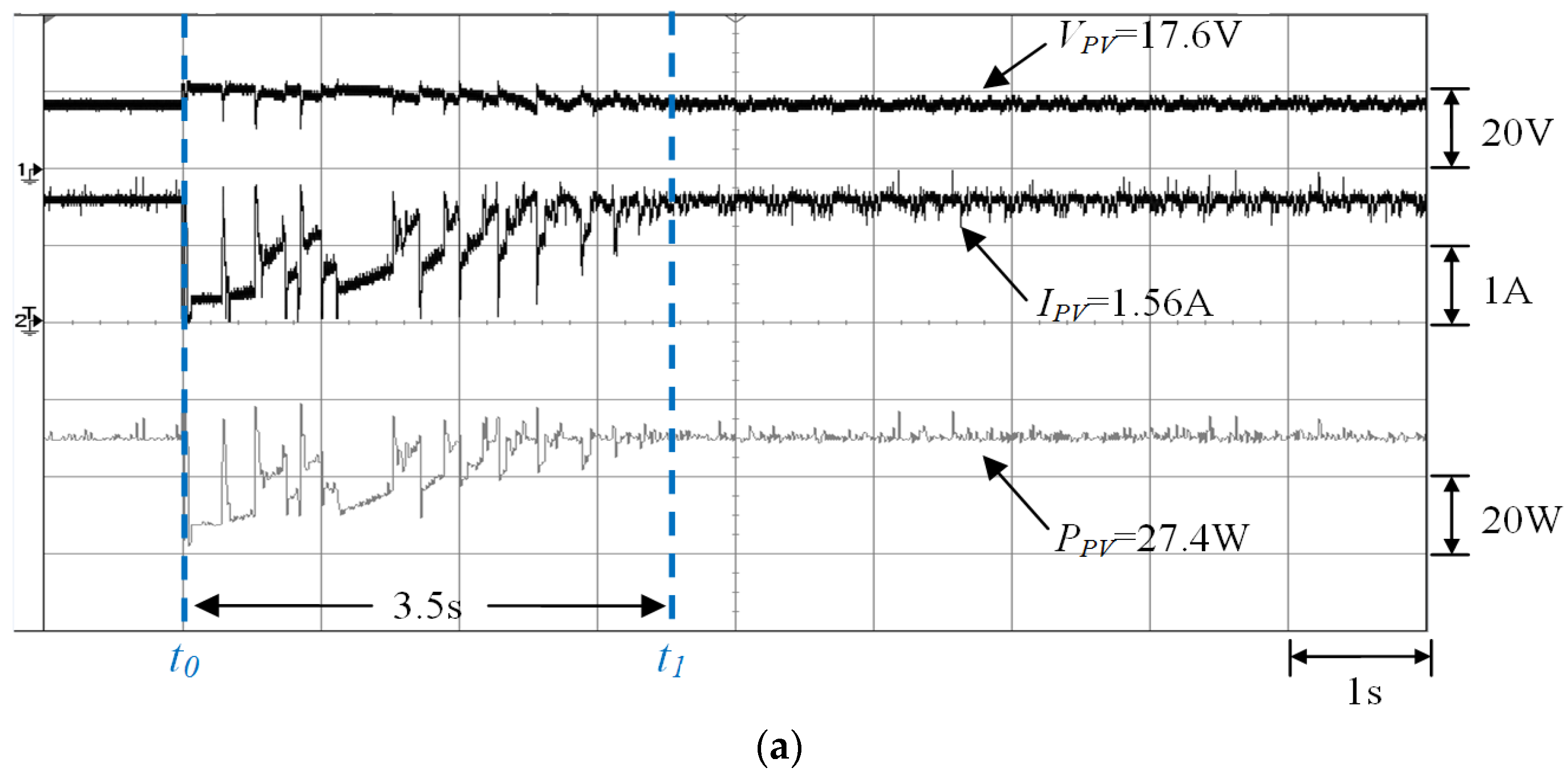
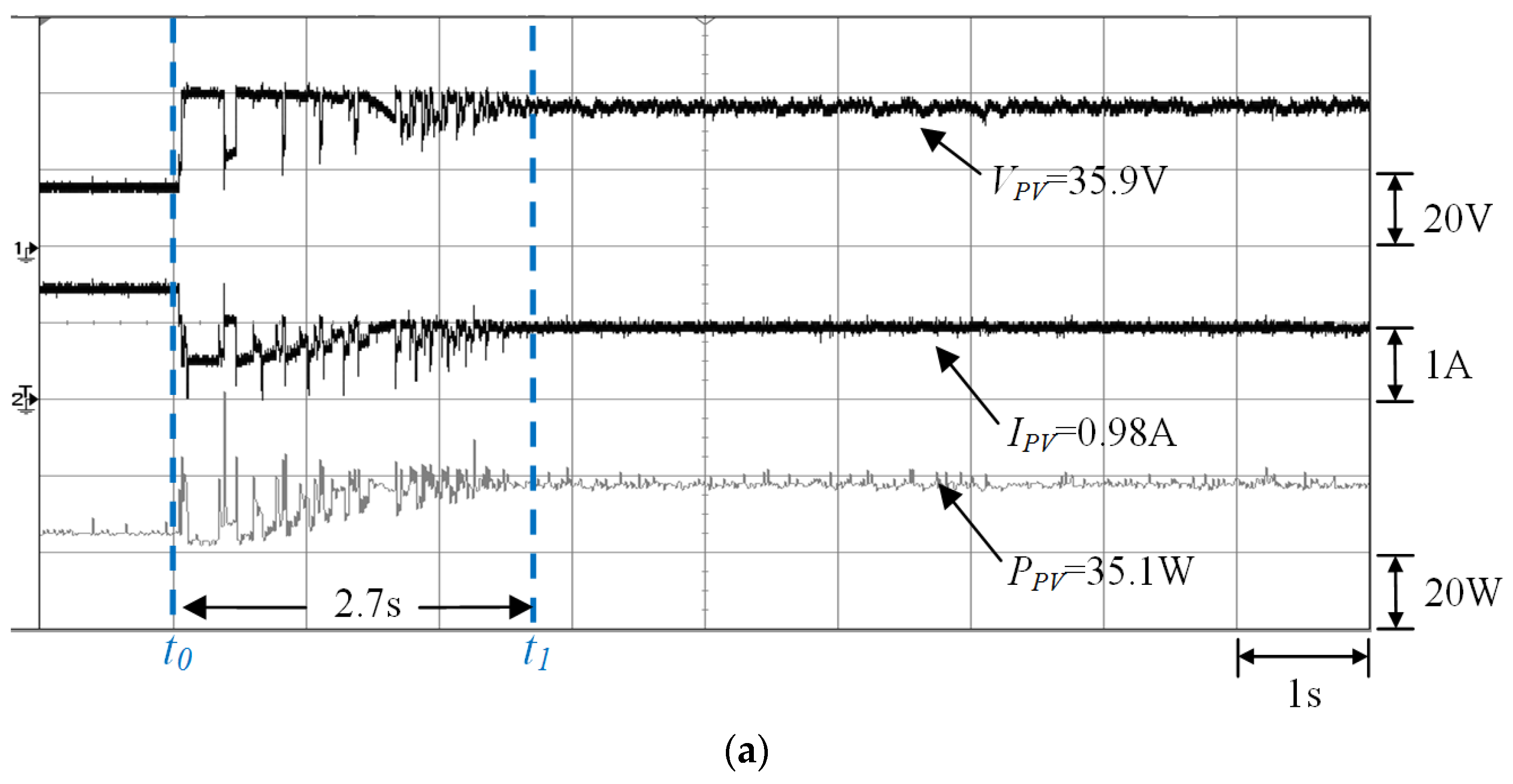
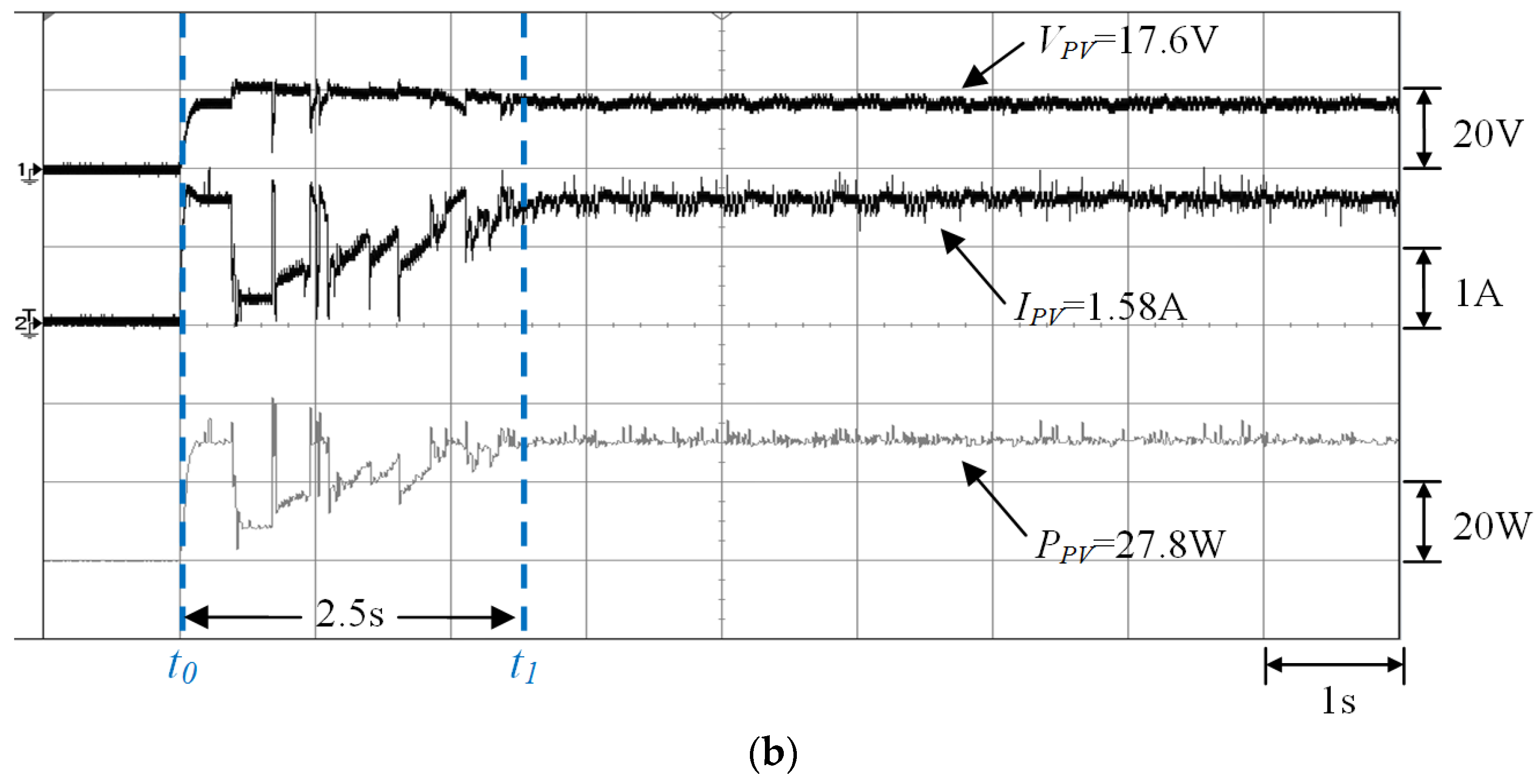
4.2.1. Case 1 (One-Serial and One-Parallel: 0% Shading)
4.2.2. Case 2 (Two-Serial and One-Parallel: 0% and 40% Shading)
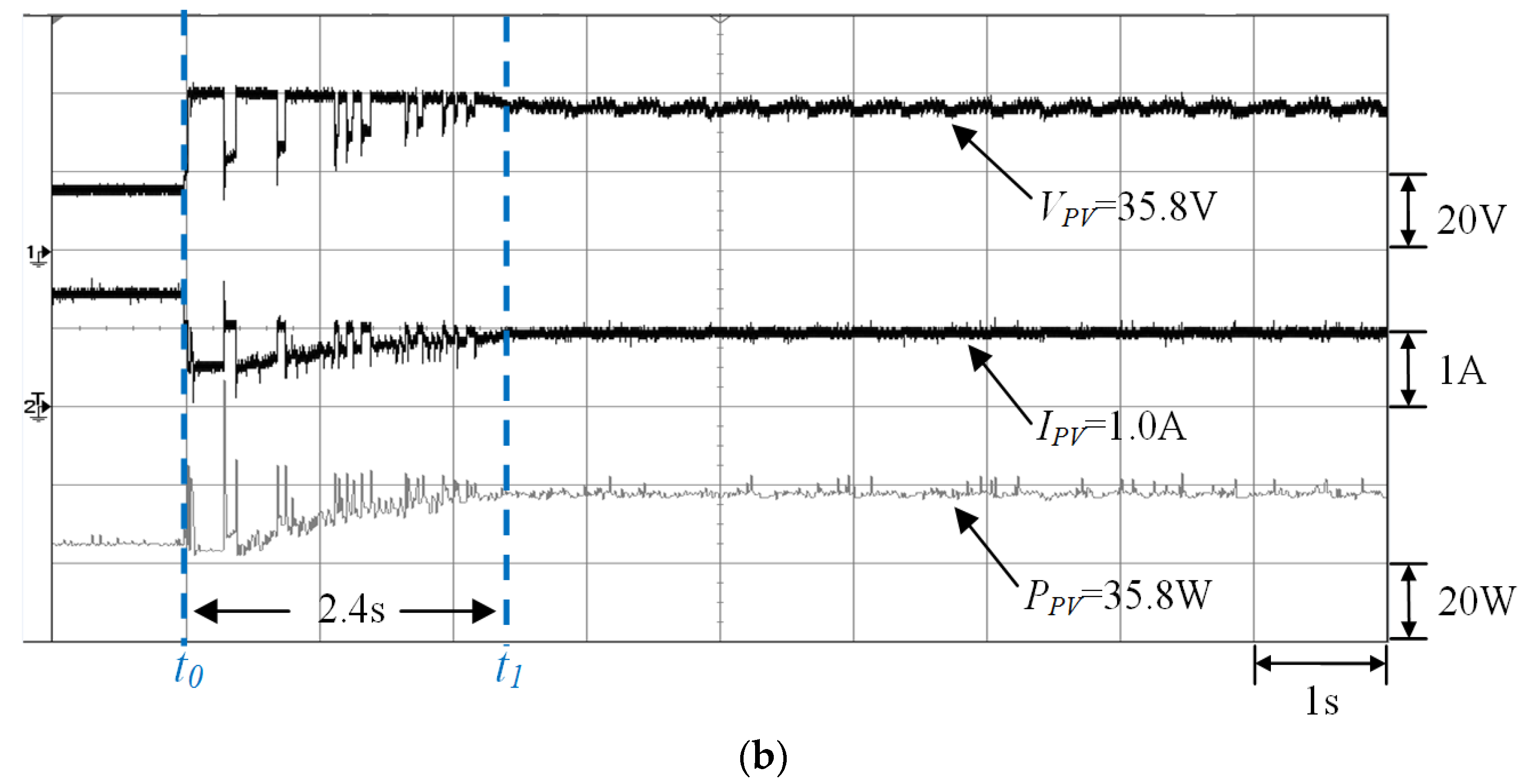
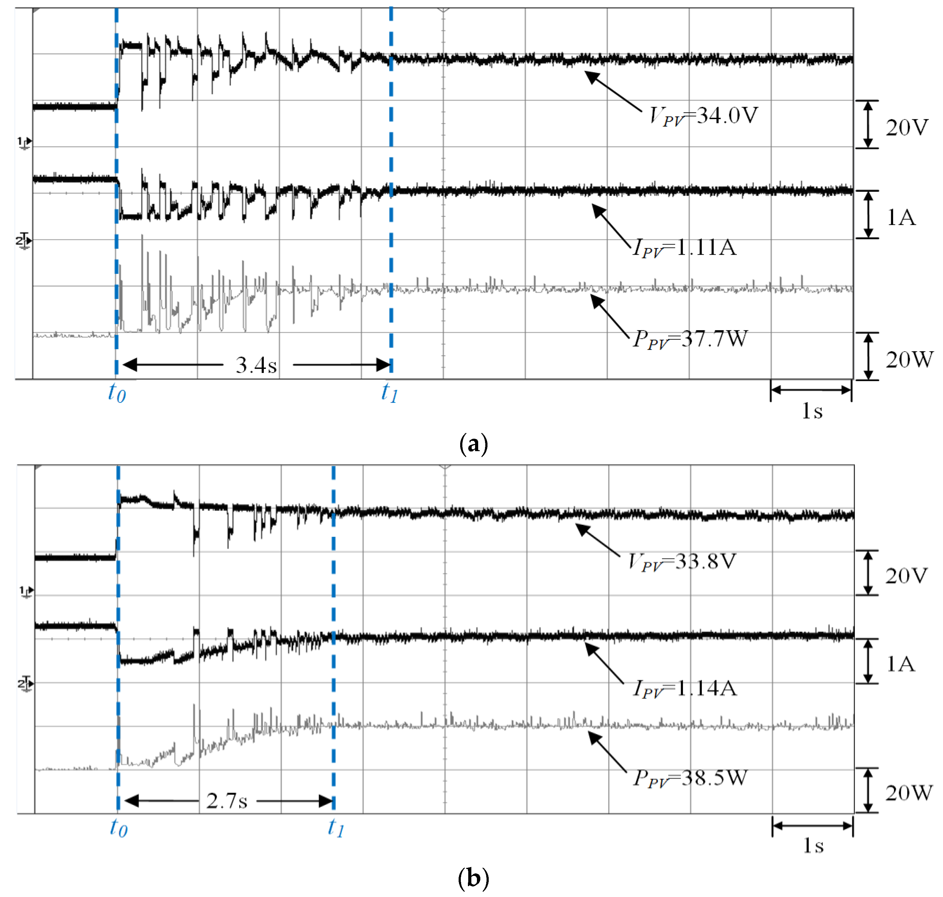
4.2.3. Case 3 (Three-Serial and One-Parallel: 0%, 30%, and 70% Shading)
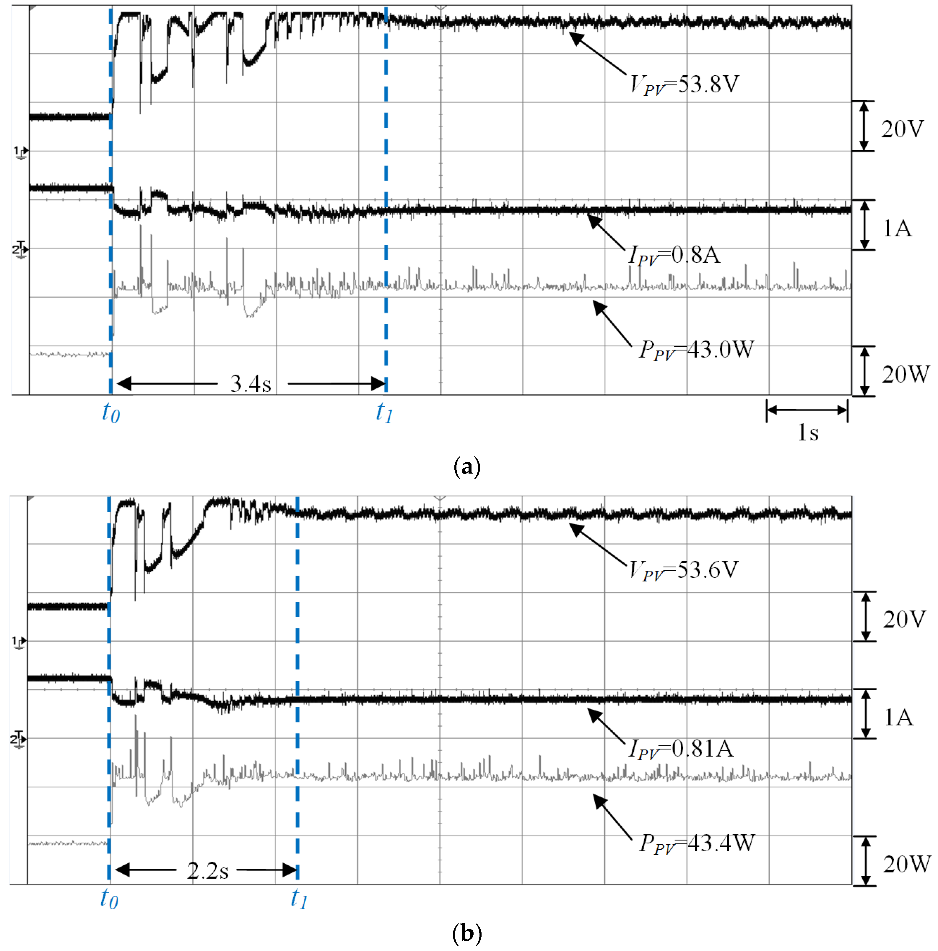
4.2.4. Case 4 (Four-Serial and One-Parallel: 0%, 30%, 50%, and 70% Shading)
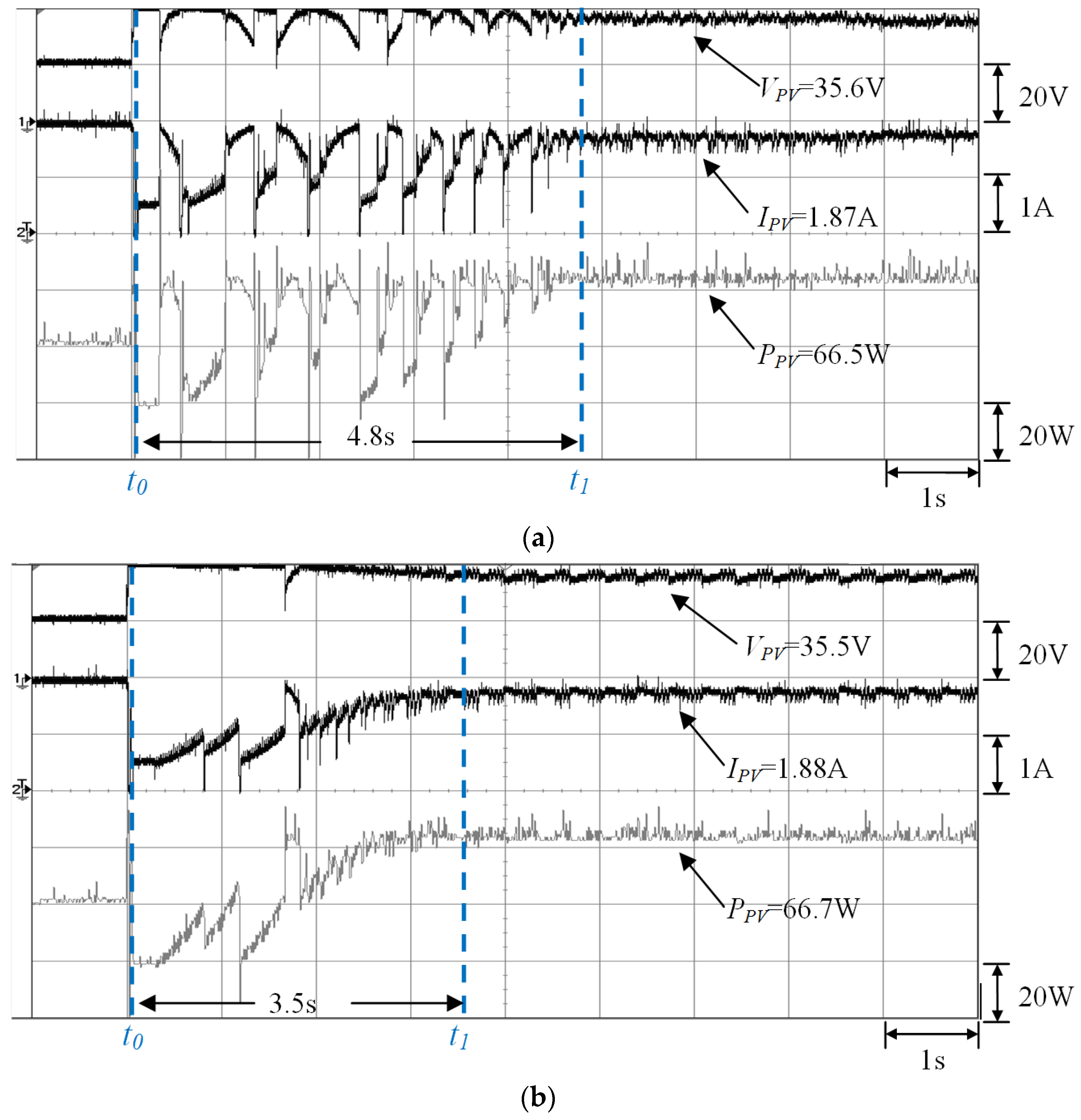
4.2.5. Case 5 (Two-Serial and Two-Parallel: (0% and 30% Shading)//(0% and 50% Shading))
4.2.6. Comparison of the Case Measurements
5. Conclusions
Acknowledgments
Author Contributions
Conflicts of Interest
References
- Wang, X.; Liang, H. Output characteristics of PV array under different insolation and temperature. In Proceedings of the IEEE 2012 Conference on Asia Pacific Power and Energy Engineering (APPEE), Shanghai, China, 27–29 March 2012; pp. 1–4.
- Femia, N.; Granozio, D.; Petrone, G.; Spagnuolo, G.; Vitelli, M. Predictive and adaptive MPPT perturb and observe method. IEEE Trans. Aerosp. Electron. Syst. 2007, 43, 934–950. [Google Scholar] [CrossRef]
- Luigi, P.; Renato, R.; Ivan, S.; Pietro, T. Optimized adaptive perturb and observe maximum power point tracking control for photovoltaic generation. Energies 2015, 8, 3418–3436. [Google Scholar] [CrossRef]
- D’Souza, N.S.; Lopes, L.A.C.; Liu, X. Comparative study of variable size perturbation and observation maximum power point trackers for PV systems. Electr. Power Syst. Res. 2010, 80, 296–305. [Google Scholar] [CrossRef]
- Lin, C.H.; Huang, C.H.; Du, Y.C.; Chen, J.L. Maximum photovoltaic power tracking for the PV array using the fractional-order incremental conductance method. Appl. Energy 2011, 88, 4840–4847. [Google Scholar] [CrossRef]
- Li, C.; Chen, Y.; Zhou, D.; Liu, J.; Zeng, J. A high-performance adaptive incremental conductance MPPT algorithm for photovoltaic systems. Energies 2016, 9, 288–305. [Google Scholar] [CrossRef]
- Mohammadmehdi, S.; Saad, M.; Rasoul, R.; Rubiyah, Y.; Ehsan, T.R. Analytical modeling of partially shaded photovoltaic systems. Energies 2013, 6, 128–144. [Google Scholar] [CrossRef]
- Balato, M.; Vitelli, M.; Femia, N.; Petrone, G.; Spagnuolo, G. Factors limiting the efficiency of DMPPT in PV applications. In Proceedings of the International Conference on Clean Electrical Power, Ischia, Italy, 14–16 June 2011; pp. 604–608.
- Vitelli, M. On the necessity of joint adoption of both distributed maximum power point tracking and central maximum power point tracking in PV systems. Prog. Photovolt. Res. Appl. 2014, 22, 283–299. [Google Scholar] [CrossRef]
- Iacca, G.; Mallipeddi, R.; Mininno, E.; Neri, F.; Suganthan, P.N. Global supervision for compact differential evolution. In Proceedings of the 2011 IEEE Symposium on Differential Evolution (SDE), Paris, France, 11–15 April 2011; pp. 1–8.
- Dorigo, M.; Birattari, M.; Stutzle, T. Ant colony optimization. IEEE Comput. Intell. Mag. 2006, 1, 28–39. [Google Scholar] [CrossRef]
- Gao, W.; Liu, S.; Huang, L. A global best artificial bee colony algorithm for global optimization. J. Comput. Appl. Math. 2012, 236, 2741–2753. [Google Scholar] [CrossRef]
- Hadji, S.; Gaubert, J.P.; Krim, F. Genetic algorithms for maximum power point tracking in photovoltaic systems. In Proceedings of the IEEE 2011—14th European Conference on Power Electronics and Applications (EPE), Birmingham, UK, 30 August–1 September 2011; pp. 1–9.
- Hadji, S.; Gaubert, J.P.; Krim, F. Experimental analysis of genetic algorithms based MPPT for PV systems. In Proceedings of the IEEE Conference on International Renewable and Sustainable Energy (IRSEC), Ouarzazate, Morocco, 17–19 October 2014; pp. 7–12.
- Tajuddin, M.F.N.; Ayob, S.M.; Salam, Z. Tracking of maximum power point in partial shading condition using differential evolution (DE). In Proceedings of the IEEE 2012 International Conference on Power and Energy (PECon), Kota Kinabalu, Malaysia, 2–5 December 2012; pp. 384–389.
- Storn, R. On the usage of differential evolution for function optimization. In Proceedings of the Biennial Conference of the North American in Fuzzy Information Processing Society (NAFIPS), Berkeley, CA, USA, 19–22 June1996; pp. 519–523.
- Lian, J.; Maskell, D.L. A uniform implementation scheme for evolutionary optimization algorithms and the experimental implementation of an ACO based MPPT for PV systems under partial shading. In Proceedings of the IEEE Symposium on Computational Intelligence Applications in Smart Grid (CIASG), Orlando, FL, USA, 9–12 December 2014; pp. 1–8.
- Sundareswaran, K.; Sankar, P.; Nayak, P.S.R.; Simon, S.P.; Palani, S. Enhanced energy output from a PV system under partial shaded conditions through artificial bee colony. IEEE Trans. Energy Convers. 2015, 6, 198–209. [Google Scholar] [CrossRef]
- Lian, K.L.; Jhang, J.H.; Tian, I.S. A maximum power point tracking method based on perturb-and-observe combined with particle swarm optimization. IEEE J. Photovolt. 2014, 4, 626–633. [Google Scholar] [CrossRef]
- Daraban, S.; Petreus, D.; Morel, C. A novel global MPPT based on genetic algorithms for photovoltaic systems under the influence of partial shading. In Proceedings of the IEEE 2013—39th Annual Conference on Industrial Electronics Society (IECON), Vienna, Austria, 10–13 November 2013; pp. 1490–1495.
- Kashif, I.; Zainal, S.; Amir, S.; Muhammad, A. A direct control based maximum power point tracking method for photovoltaic system under partial shading conditions using particle swarm optimization algorithm. Appl. Energy 2012, 99, 414–422. [Google Scholar] [CrossRef]
- Chao, K.H.; Lin, Y.S.; Lai, U.D. Improved particle swarm optimization for maximum power point tracking in photovoltaic module arrays. Appl. Energy 2015, 158, 609–618. [Google Scholar] [CrossRef]
- Rao, R.V.; Savsani, V.J.; Vakharia, D.P. Teaching-learning-based optimization: A novel method for constrained mechanical design optimization problems. J. Comput. Aided Des. 2011, 43, 303–315. [Google Scholar] [CrossRef]
- Satapathy, S.C.; Naik, A.; Parvathi, K. Weighted teaching-learning-based optimization for global function optimization. Appl. Math. Sci. Res. Publ. 2013, 4, 429–439. [Google Scholar] [CrossRef]
- Rao, R.V.; Patel, V. An improved teaching-learning-based optimization Algorithm for solving unconstrained optimization problems. Comput. Sci. Eng. Electr. Eng. 2013, 20, 710–720. [Google Scholar] [CrossRef]
- SANYO HIP 2717 Datasheet. Available online: http://iris.nyit.edu/~mbertome/solardecathlon/SDClerical/SD_DESIGN+DEVELOPMENT/091804_Sanyo190HITBrochure.pdf (accessed on 15 January 2016).
- Chao, K.H.; Chao, Y.W.; Chen, J.P. A circuit-based photovoltaic module simulator with shadow and fault setting. Int. J. Electron. 2016, 103, 424–438. [Google Scholar] [CrossRef]
- Solar Pro Official Website. Available online: http://lapsys.co.jp/english (accessed on 10 May 2016).
- Rao, R.V.; Patel, V.; Chen, J.P. An elitist teaching-learning-based optimization algorithm for solving complex constrained optimization problems. Int. J. Ind. Eng. Comput. 2012, 3, 535–560. [Google Scholar] [CrossRef]
- Graditi, G.; Adinolfi, G.; Femia, N.; Vitelli, M. Comparative analysis of synchronous rectification boost and diode rectification boost converter for DMPPT applications. In Proceedings of the 2011 IEEE International Symposium on Industrial Electronics (ISIE), Gdansk, Poland, 27–30 June 2011; pp. 1000–1005.
- Hart, D.W. Introduction to Power Electronics; Prentice Hall: New York, NY, USA, 2003. [Google Scholar]
- TMS320F2808 Data Sheet. Available online: http://www.ti.com/lit/ds/symlink/tms320f2808.pdf (accessed on 12 March 2016).


| Parameter | Value |
|---|---|
| Rated maximum power output (Pmp) | 27.8 W |
| MPP current (Imp) | 1.63 A |
| MPP voltage (Vmp) | 17.1 V |
| Short-circuit current (Isc) | 1.82 A |
| Open-circuit voltage (Voc) | 21.6 V |
| Module dimensions | 496 mm × 524 mm |
| Component | Model Number and Specifications |
|---|---|
| Inductance (Lm) | 3.3 mH |
| Input capacitance (Cin) | 220 μF/160 V |
| Output capacitance (Cout) | 390 μF/450 V |
| Switching frequency (fs) | 20 kHz |
| Power MOSFET (S) | IRF460 (500 V/20A) |
| Diode (D) | DSEP30-12A (1200 V/30A) |
| Parameter | Setting |
|---|---|
| Number of students (NP) | 4 |
| Number of iterations (E) | 40 |
| Teaching step (ri) | Random value between 0 and 1 |
| Teaching factor (TF) | 1 or 2 |
| Parameter | Setting |
|---|---|
| Teaching factor (TF) |
| Case | Serial and Parallel Configurations and Shading Situations | Number of Peaks in the P–V Characteristic Curves |
|---|---|---|
| 1 | One-serial and one-parallel with 0% shading | Single |
| 2 | Two-serial and one-parallel with 0% and 40% shading | Double |
| 3 | Three-serial and one-parallel with 0%, 40%, and 70% shading | Triple |
| 4 | Four-serial and one-parallel with 0%, 30% shading, 50%, and 70% shading | Quadruple |
| 5 | Two-serial and two-parallel with (30% and 0% shading)//(0% and 50% shading) | Double |
| Case | P–V Curve Peaks | ACO [17] | PSO [21] | Conventional TLBO | Proposed I-TLBO | ||||
|---|---|---|---|---|---|---|---|---|---|
| Average Tracking Time | Average MPP | Average Tracking Time | Average MPP | Average Tracking Time | Average MPP | Average Tracking Time | Average MPP | ||
| 1 | Single | 4.3 s | 27.5 W | 3.4 s | 27.3 W | 3.3 s | 27.0 W | 2.5 s | 27.8 W |
| 2 | Double | 4.8 s | 35.3 W | 3.0 s | 35.0 W | 2.8 s | 35.1 W | 2.4 s | 35.8 W |
| 3 | Triple | 5.1 s | 37.5 W | 3.8 s | 37.0 W | 3.4 s | 37.2 W | 2.7 s | 38.5 W |
| 4 | Quadrupe | 5.6 s | 43.2 W | Tracking failed | 35.7 W | 3.6 s | 43.0 W | 2.2 s | 43.4 W |
| 5 | Double | 5.8 s | 66.3 W | 5.2 s | 64.7 W | 4.8 s | 66.1 W | 3.7 s | 66.7 W |
© 2016 by the authors; licensee MDPI, Basel, Switzerland. This article is an open access article distributed under the terms and conditions of the Creative Commons Attribution (CC-BY) license (http://creativecommons.org/licenses/by/4.0/).
Share and Cite
Chao, K.-H.; Wu, M.-C. Global Maximum Power Point Tracking (MPPT) of a Photovoltaic Module Array Constructed through Improved Teaching-Learning-Based Optimization. Energies 2016, 9, 986. https://doi.org/10.3390/en9120986
Chao K-H, Wu M-C. Global Maximum Power Point Tracking (MPPT) of a Photovoltaic Module Array Constructed through Improved Teaching-Learning-Based Optimization. Energies. 2016; 9(12):986. https://doi.org/10.3390/en9120986
Chicago/Turabian StyleChao, Kuei-Hsiang, and Meng-Cheng Wu. 2016. "Global Maximum Power Point Tracking (MPPT) of a Photovoltaic Module Array Constructed through Improved Teaching-Learning-Based Optimization" Energies 9, no. 12: 986. https://doi.org/10.3390/en9120986
APA StyleChao, K.-H., & Wu, M.-C. (2016). Global Maximum Power Point Tracking (MPPT) of a Photovoltaic Module Array Constructed through Improved Teaching-Learning-Based Optimization. Energies, 9(12), 986. https://doi.org/10.3390/en9120986