1. Introduction
Wind turbines are increasingly installed in the northeastern and the mid-Atlantic US, Canada, and Northern Europe due to good wind resources and land availability. In these locations, humidity, along with low temperatures in the winters, increases the risks of ice accumulation on wind turbine components. Icing of wind turbine rotor blades reduces the lift force and increases drag force acting on the aerofoil sections of the blade [
1,
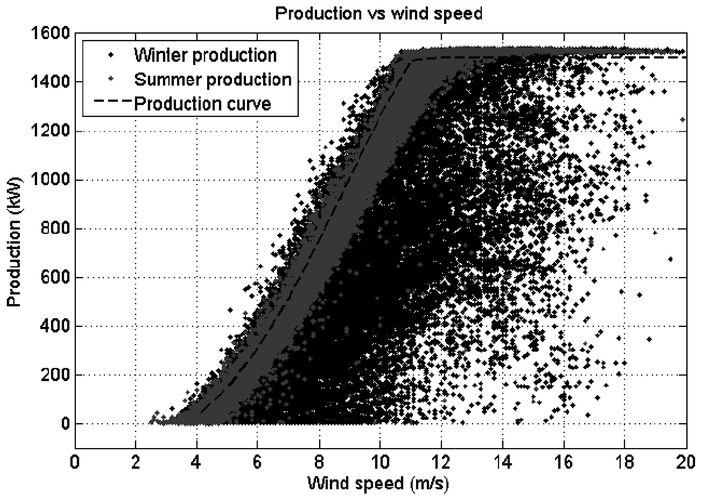
2], which causes a reduction in the turbine power output. The power curve of a typical wind turbine [
2] with icing is shown in
Figure 1, where the impact of icing on power production is clearly visible. In addition to that nacelle vibration amplitudes increase during icing conditions, so icing can be detected more reliably using power curve analysis along with measuring nacelle vibrations [
3]. Icing causes mass and aerodynamic imbalances in the rotating blades which increases loading in the mechanical components like blades, towers, bearings, gearboxes, etc. Increased vibrations reduce the fatigue life of the tower and blades; aerodynamic property changes in the aerofoil due to icing contribute more to the fatigue life than the ice mass changes [
4]. Etemaddar et al. [
5] investigated the effects of atmospheric ice accumulation on the aerodynamic performance and structural response of wind turbines and they predicted that the relative change in mean value is bigger than the change in standard deviation for most of the response quantities (rotor speed, torque, power, thrust and structural loads) of the iced blade.
Icing on wind turbines introduces additional complexity into the dynamic analysis of the system, as ice accumulation on the blades is not uniform and its distribution changes under different stages of icing and ice shedding during operation. Ice mass on the blade reduces its natural frequencies and raises the risks of resonance. This shift in natural frequencies can be used to detect ice and monitor its growth on the wind turbine blades both in operating and standstill conditions [
6,
7,
8]. Lorenzo et al. [
9] investigated the influence of ice mass on the natural frequencies of the National Renewable Energy Laboratory (NREL) 5 MW wind turbine by extracting modal parameters through operational modal analysis. Alsabagh et al. [
10] considered different ice mass distributions, as defined in the ISO 12494 Standard, on a multi-megawatt wind turbine. They analyzed the influences of ice mass on natural frequencies and dynamic magnification factors (ratio of the dynamic deflection to static deflection), by considering only the mass changes in the blade. As icing causes structural and aerodynamic changes in the blade, it is important to investigate their influence on the modal damping along with the natural frequencies as aerodynamic loads on the blade contribute to the modal damping. The shape of ice accumulated on the blade depends on many parameters, which vary stochastically in space and time. Instead of predicting ice shapes on the turbine blade, this study considers two different ice shapes predicted on a National Advisory Committee for Aeronautics (NACA) 0012 aerofoil in [
11] which are replicated on the Tjaereborg 2 MW wind turbine blade aerofoils to investigate their influence on the modal behavior of the blade. These two ice shapes are approximated using discrete Fourier sine series whose coefficients can be scaled to add any desired amount of ice on the leading edge of aerofoil sections. Structural and aerofoil details of this wind turbine blade are reported in [
12,
13], which is a constant speed pitch controlled turbine. Wind turbine blades are made of aerofoil cross sections which are twisted and tapered along the blade length. The vibration behavior in bending and torsion are therefore coupled. Kim and Lee [
14] analyzed wind turbine blade modal characteristics using the assumed modes method, which is computationally efficient and accurate. In this study, partial differential equations governing blade in-plane (edgewise), out-of-plane (flapwise), axial and torsional vibrations are derived using Hamilton’s principle, which are then analyzed using finite element method (FEM). Beddoes-Leishman unsteady attached flow aerodynamic model is used together with the FEM model of the blade. Static aerodynamic coefficients (lift, drag and pitching moment) of the aerofoils are calculated using the JavaFoil [
15] program. Two different ice shapes with two different ice mass distributions are considered in this study and their influences on the blade’s structural and aerodynamic properties are evaluated. Natural frequencies and damping factors of the iced blades are determined using eigenvalue analysis of the aeroelastic equations of motion.
2. Structural Model
Partial differential equations governing the blade vibrations are derived in this section based on the derivation in [
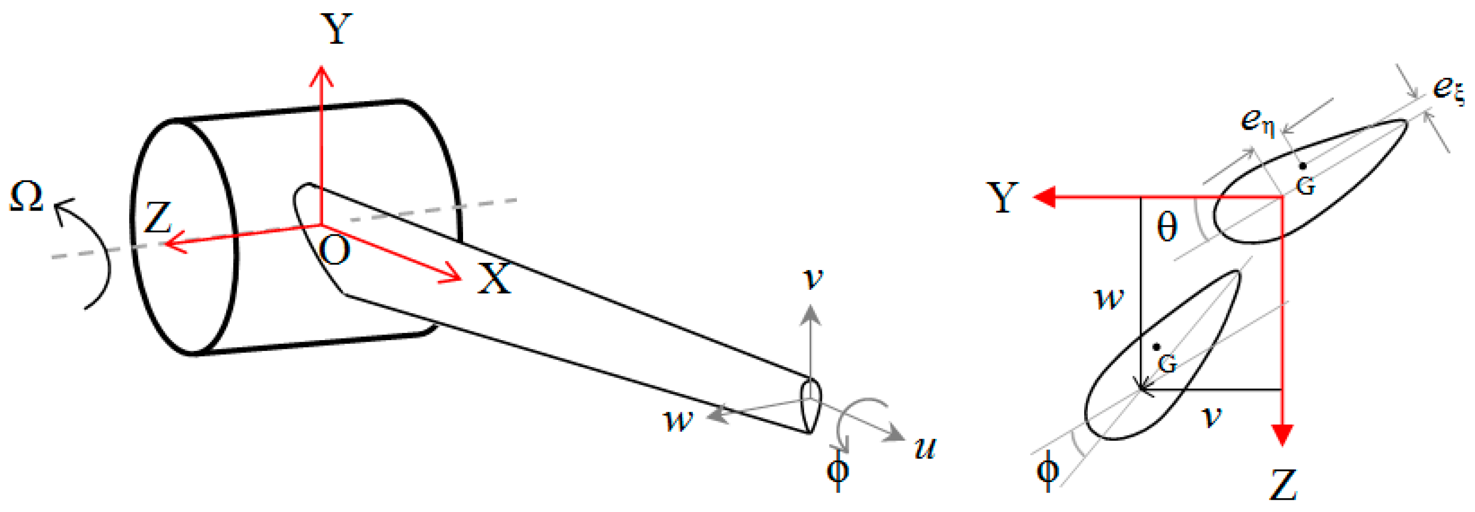
14]. A rotating coordinate system OXYZ fixed at the hub center, as shown in
Figure 2, is considered to derive governing equations of the wind turbine blade vibrations. Pitch axis of the blade (assumed to pass through quarter chord points of the aerofoil sections) coincides with the x-axis of the coordinate system. Blade vibrations degrees of freedom (DOF) in axial (
u), chordwise (
v), flapwise (
w) and torsional (φ) motions are considered in this study.
The position vector of the center of gravity (
G) of an aerofoil section at a distance
x from the blade root, assuming small torsional vibrations (φ) is given in Equation (1), and its velocity and angular velocity vectors are given in Equations (2) and (3), which are used to determine the kinetic energy of the blade.
where
h is the hub radius;
eη,
eξ are the distances from the pitch axis to the center of gravity along the chord line and perpendicular to the chord line, respectively; θ is the sum of blade twist and pitch angles; Ω is the blade angular velocity; and (·) refers to the temporal differentiation.
The equations of kinetic energy, strain energy and potential energy (due to the centrifugal and gravitational forces) of the whole blade are given in Equations (4)–(6).
where
;
Fax is the axial force acting on the blade section which is at a distance of
x from the blade root;
T, Π
E, Π
C+G are the blade’s kinetic energy, strain energy and potential energy (due to centrifugal and gravity forces), respectively; ρ
A, JP are the mass density and polar mass moment of inertia of the blade section about the pitch axis, respectively;
l is the blade length;
EIY, EIZ, EIYZ are the blade flexural rigidities and
GJ is the torsional rigidity of the blade;
g is the acceleration due to gravity; and (′) refers to the spatial differentiation with respect to
x.
Work done by the generalized forces
fu,
fv,
fw,
fφ corresponding to the
u,
v,
w, φ degrees of freedom is given below.
Linear partial differential equations governing the vibration behavior of wind turbine blade are derived using the Hamilton’s principle given in Equation (8) by assuming small amplitude vibrations. The resulting equations are given in Appendix.
3. Aerodynamic Model
Blade element momentum (BEM) theory [
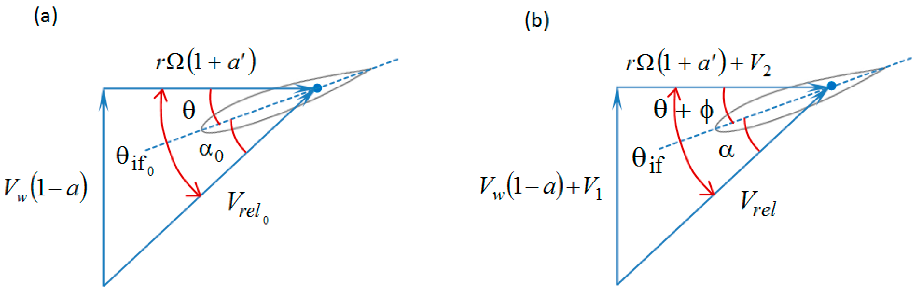
16] is used to calculate the aerodynamic loads considering Prandtl’s tip loss factor and Glauert corrections. The wind enters aerofoil sections of the blade with a relative velocity, which is a resultant of its tangential velocity due to rotation and wind velocity. Velocity triangles without and with considering blade vibrations are shown in
Figure 3. Expressions for the inflow angle and angle of attack (AOA) without considering blade vibrations are given in Equations (9) and (10).
where
are the inflow angle and angle of attack, respectively, ignoring the blade vibrations; θ is the sum of blade pitch angle and aerofoil section twist angle;
Vw and Ω are the wind velocity and blade angular velocity, respectively;
r is the radial distance of the blade section from the hub center along the pitch axis; and
a and
a’ are the axial and tangential induction factors, respectively.
Blade vibration velocities change the relative velocity of wind entering the blade section and inflow angle as shown in
Figure 3b. As the blade vibrations DOF are defined about the pitch axis, both the inflow angle and the AOA evaluated at the ¾ chord point now depend on the torsional vibrations. Expressions for the inflow angle, angle of attack considering blade vibrations are given in Equations (11) and (12).
where
;
;
are the inflow angle and angle of attack considering blade vibrations, respectively;
are the velocities of the blade edgewise, flapwise and torsional vibrations, respectively; φ refers to the blade torsional vibrations;
bhc is the half chord length of the aerofoil; and
, ε is the distance between pitch axis and the midpoint of the chord.
Change in the AOA due to blade vibrations can be approximated [
17] according to Equation (13).
Lift, drag and pitching moment coefficients at the angle of attack α can be approximated using first-order Taylor series expansion about α
0 as given in Equation (14).
where
CL,
CD,
CM are the lift, drag and moment coefficients of the aerofoil, respectively; and
CL′,
CD′,
CM′ are the slopes of the lift, drag and moment coefficient curves. The approximation of these coefficients about α
0 for small ∆α values will have an error of less than one percent.
The total lift force generated by wind blowing over the blade consists of circulatory and non-circulatory (virtual or added mass) contributions, which are given in Equations (15) and (16). Circulatory lift accounts for the unsteady time lag effects caused by the vorticity shed into the wake [
18,
19].
where
; φ
0 is the value of Wagner’s indicial function
at
t = 0, where
,
A1,
A2,
b1,
b2 are the parameters of two exponential time-lag terms;
z1,
z2 refer to additional state variables that describe time lag effects of the wake; ρ
a refers to the mass density of the air; and
is the resultant of velocity components
Vw(1 −
a) and
rΩ(1 +
a′).
Total drag force of the blade consists of two parts: static and induced drag [
18], which are given in Equations (18) and (19).
Total pitching moment loads acting on the blade consist of circulatory and non-circulatory contributions [
18] similar to the lift force and they are given in Equations (21) and (22).
The
z1,
z2 terms are additional state variables that describe time lag effects of the wake and they are computed from the first order differential equations [
18]:
The coefficients of exponential terms in the Wagner’s function are given in [
20] to approximate the response of a flat plate. The same values are used in this study, they are given as follows
A1 = 0.165;
A2 = 0.335;
b1 = 0.0455;
b2 = 0.3.
The generalized forces corresponding to the blade vibrations
u,
v,
w, φ are given in Equation (25) in terms of aerodynamic loads defined above.
4. Leading Edge Ice Shapes
Two types of icing occur in wind turbines: glaze and rime ice. Glaze ice is caused by freezing rain or wet in-cloud icing, and normally causes smooth evenly distributed ice accretion. Rime forms through the deposition of super-cooled fog or cloud droplets and is the most common form of in-cloud icing. Rime tends to form vanes on the windward side of the blades. Icing of the blade depends on the geometric parameters (thickness, chord length and the radial location of the aerofoil section) and site-specific operating conditions (ambient temperature, moisture content of the air, wind velocity and the duration of icing event). Most of these parameters vary stochastically in space and time. Multi-physics analyses involving heat transfer and computational fluid dynamics (CFD) approach are used in the tools LEWICE [
21], TURBICE [
1], FENSAP-ICE [
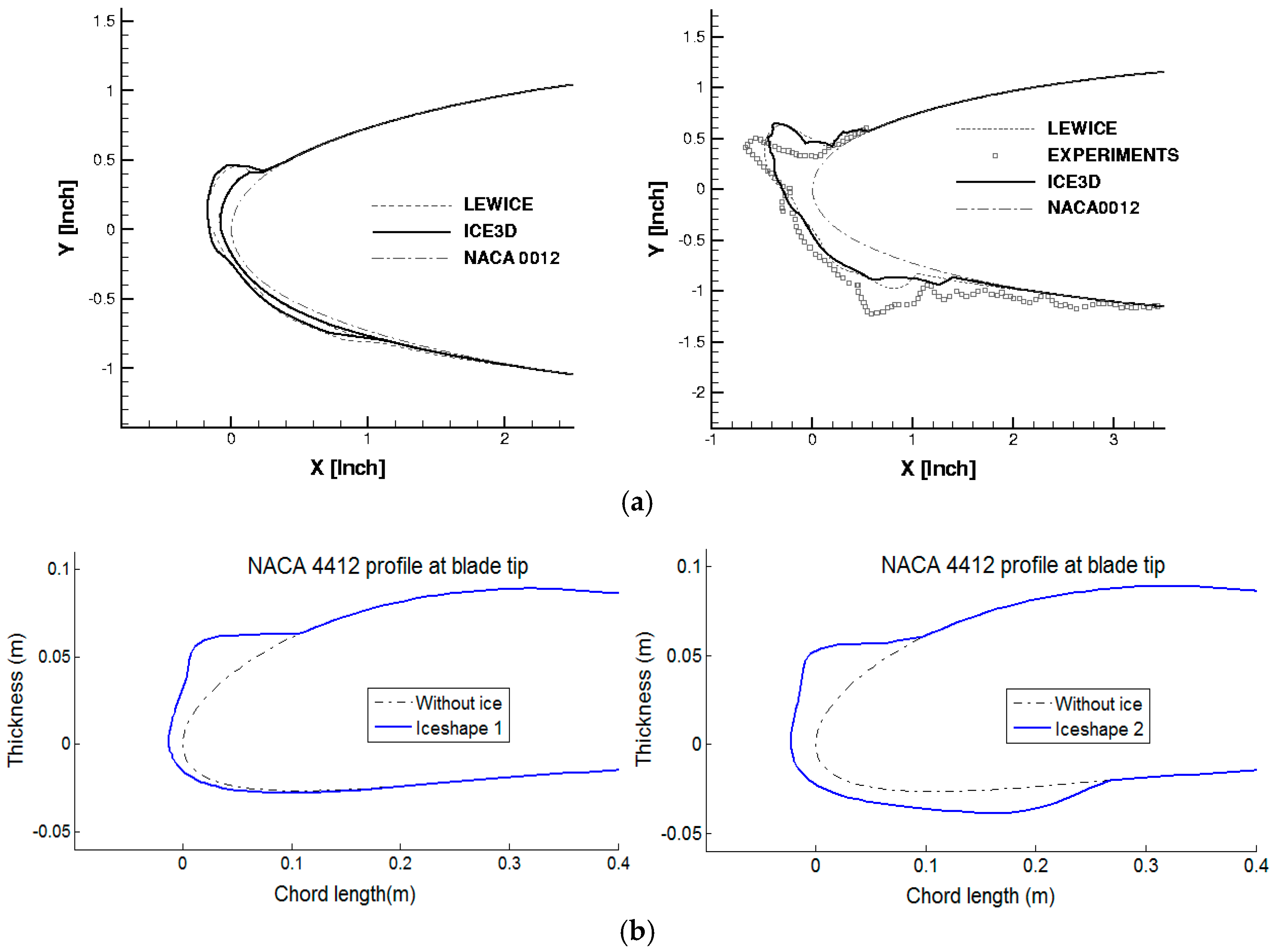
11] to predict atmospheric icing on wind turbine blades. The inputs to these tools are wind velocity, ambient temperature, liquid water content (LWC), median volume diameter (MVD), or droplet size and duration of the icing event. All these parameters are different for different wind turbine sites and they even change for turbines within the site. In this study, instead of predicting ice shapes using these parameters, two ice shapes predicted in [
11] are considered. These two shapes, Ice shapes 1 and 2 (shown in
Figure 4a) are approximately replicated using a discrete Fourier sine series on the current Tjaereborg wind turbine blade’s aerofoil in
Figure 4b.
5. Ice Mass Distribution
Ice accumulation on the wind turbine blades is not same across the blade length. The ice accumulation on wind turbines depends on many parameters and it increases with the duration of icing event. Ice on the blades causes more loads and vibrations in the turbine. In order to certify wind turbines and their components for cold climate operation, Germanischer Lloyd (GL) [
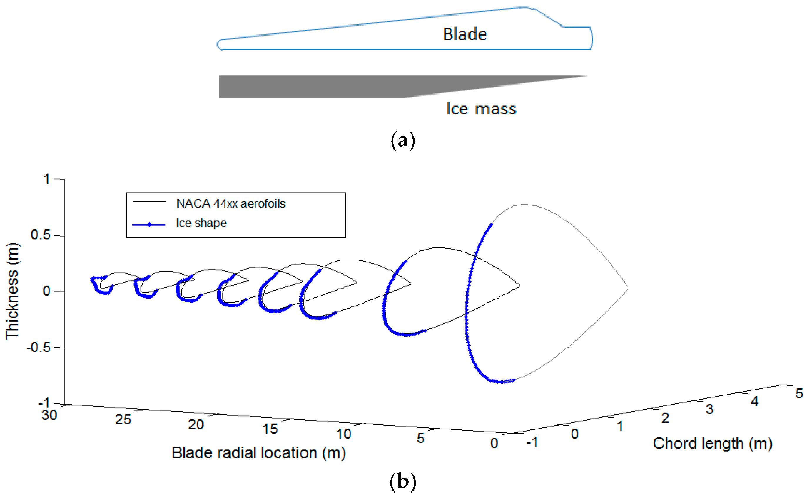
22] proposed a guideline that defines the maximum ice mass distribution on the blade to calculate loads acting on the turbine in various design load cases. The actual ice mass may be lower than this limit, but the turbines are certified for loads corresponding to this mass limit. More ice accumulates near the blade tip as air enters here with higher relative velocity. Also, this portion of the blade sweeps more area in rotation compared to the portion of the blade near the root. GL ice mass distribution is defined by modeling this nature of ice accumulation, so this guideline is more applicable in the absence of global design guidelines for calculating wind turbine loads in cold climate. In the GL guideline, ice mass density linearly increases from zero at the blade root to a value of μ
E until the half-blade length; thereafter, mass density is constant towards the tip as shown in
Figure 5a. The value of μ
E is calculated as follows [
22]:
where ρ
E is the ice density (700 kg/m
3);
;
R is the rotor radius in meter unit,
R1 = 1 m; and
cmax,
cmin are the maximum and minimum chord lengths of the blade in meter unit, respectively.
For the current Tjaereborg wind turbine blade, the value of μ
E is 19.19 kg/m, which corresponds to an ice mass of 417 kg (about 5% of blade mass). In this study, two ice mass distributions 50% and 100% of μ
E value are considered along the blade and the case of 100% GL ice mass distribution with Ice shape 2 is shown in
Figure 5b.
6. Results and Discussion
Blade structural and aerodynamic models described in the previous sections are used to model Tjaereborg 2 MW wind turbine blade vibrations. Details about the structural and aerofoil sections of the blade are reported in [
12,
13]. Static aerodynamic coefficients (
CL,
CD,
CM) of the blade’s aerofoil sections are calculated using the JavaFoil [
15] program. Aeroelastic partial differential equations obtained after introducing generalized forces in the structural equations are analyzed using FEM. Eigenvalue analysis is carried out to obtain natural frequencies and damping factors of the blade vibration modes. The first few modal frequencies of the non-rotating blade without ice are given in
Table 1 and compared with the frequencies reported in [
23] for checking the accuracy of the FEM model of the structural vibrations. These frequencies are calculated by ignoring aerodynamic loads. The current FEM model’s natural frequencies closely match with those reported in [
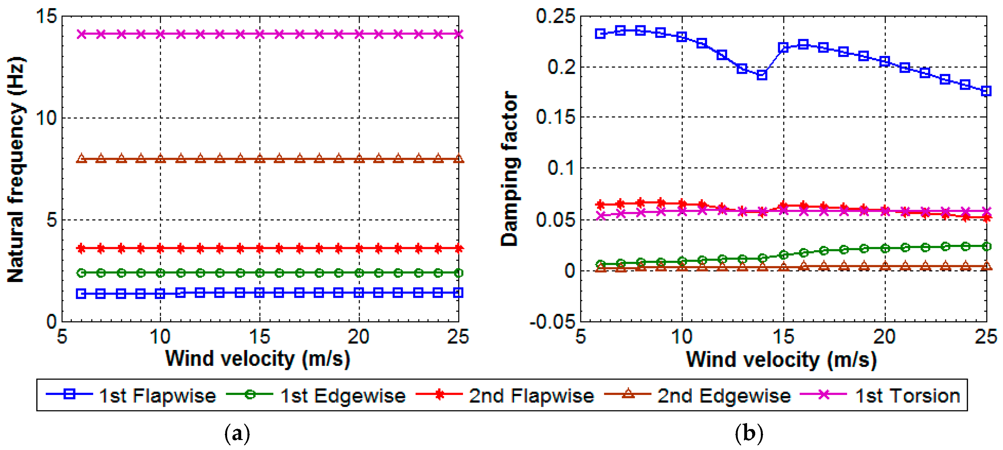
23]. Aeroelastic natural frequencies and modal damping factors of this blade without ice are calculated at the operating wind velocities between 5 m/s and 25 m/s and shown in
Figure 6. Natural frequencies slightly change with wind velocities and these changes are not noticeable in the plot, whereas modal damping changes are noticeable. The wind turbine operates at zero pitch angle from the cut-in to rated wind velocity, where turbine power output increases from the minimum to its rated power and the angle of attack (α
0) steadily increases. Above the rated wind velocity, turbine blades are pitched to generate its rated power, so the rate of change in the angle of attack with respect to wind velocity increases due to pitching. This introduces different slopes of the aerodynamic coefficient curves, i.e.,
CL′,
CD′,
CM′ in Equations (16), (17) and (22). These will change aerodynamic damping in the aeroelastic equations of motion, modal damping factors will thus have a sharp change just above the rated wind velocity. Positive damping factors of the vibration modes in the operating wind velocity range with clean aerofoils (
Figure 6b) indicate the stable behavior of the blade vibrations.
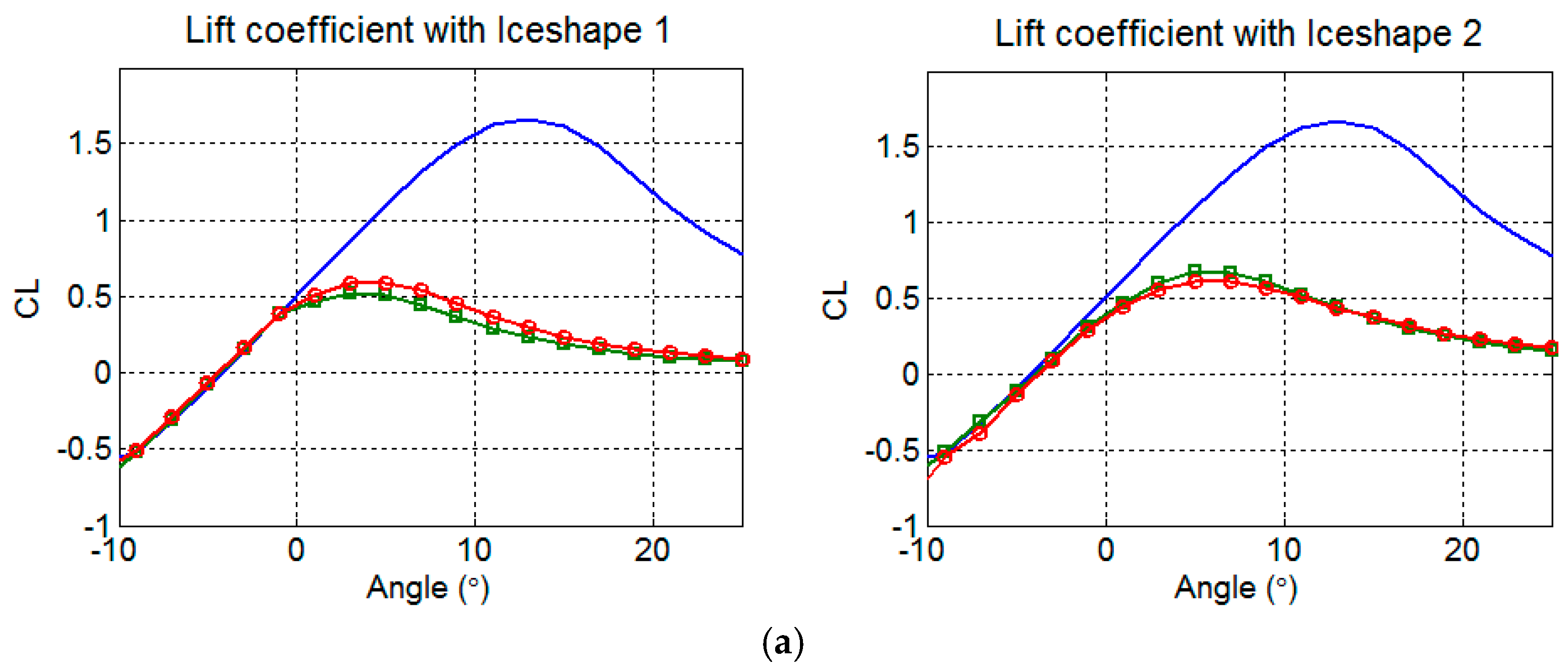
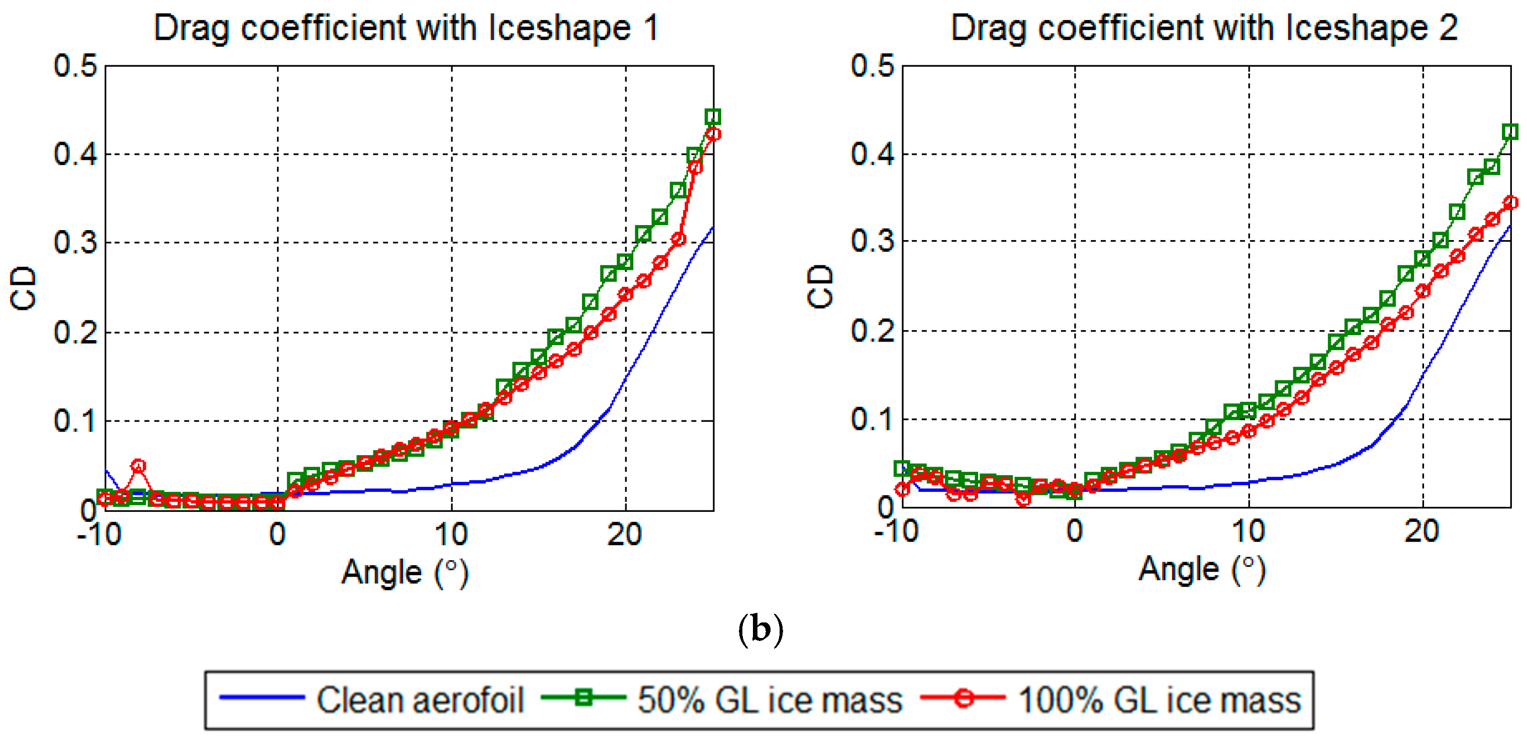
Aerofoil sections near the blade root are larger in size, but accumulate less ice, whereas aerofoil sections near the blade tip are smaller in size, but accumulate more ice, since they sweep through a larger area in rotation. Thus the aerofoil shapes near the blade tip are more distorted with ice whose aerodynamic behavior is most affected. Two different ice mass distributions 50% and 100% of the GL ice mass limit with the ice shapes shown in
Figure 4b are created on the blade and their static aerodynamic coefficients (lift, drag and pitching moment) are determined using JavaFoil [
15]. Lift and drag coefficients of the iced NACA 4412 aerofoil used at the blade tip are compared with that of the clean aerofoil in
Figure 7. These coefficients of the iced aerofoil are obtained after normalizing with the new chord length, which increases due to ice. Distortion in the aerofoil shape with ice reduces the lift force and increases drag force on the aerofoil sections (
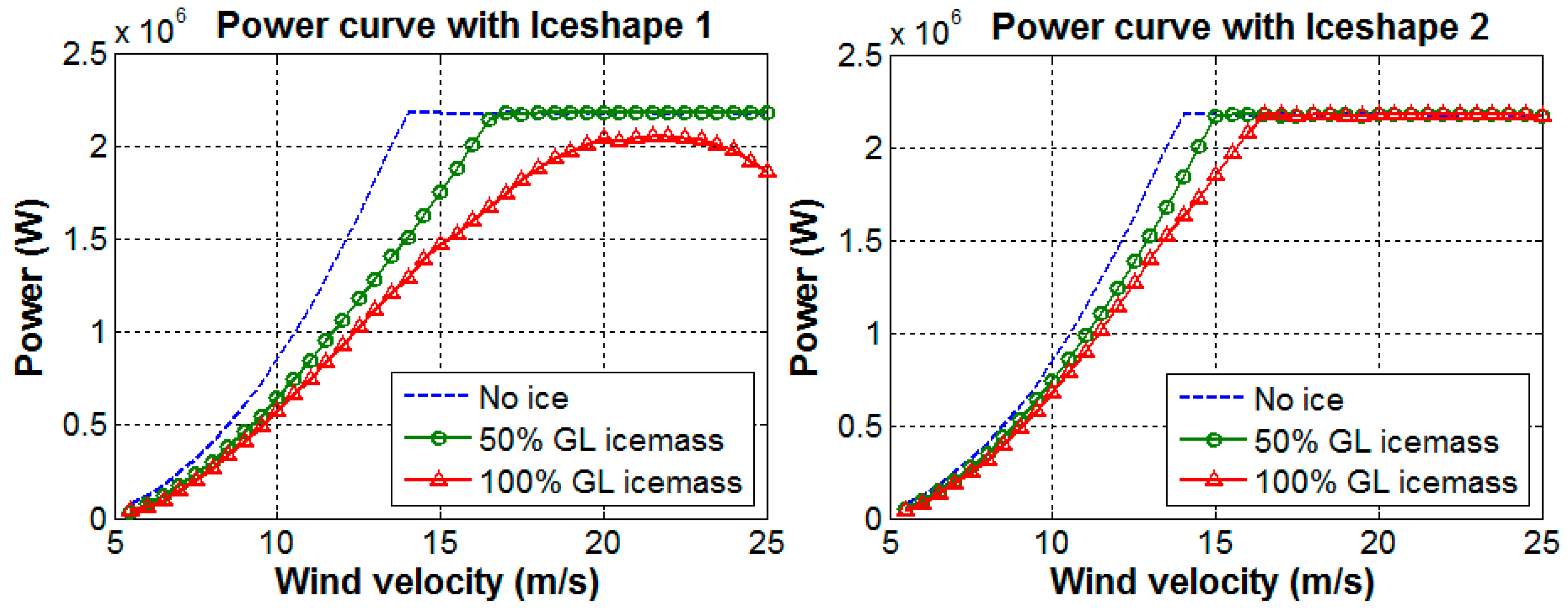
Figure 7), which causes a drop in the power output. The power curves predicted for the cases of the clean and iced blade are shown in
Figure 8. Wind turbines with iced blades would not be able to produce rated power at their rated wind velocities. Iceshape 1 causes more drop in the power output compared to the Ice shape 2 for the same amounts of ice mass. This indicates that the aerodynamic behavior of the blade with Ice shape 1 is more deteriorated than with the Ice shape 2. Here, the blade with 100% GL ice mass defined by Ice shape 1 is not able to produce rated power in its entire operating wind velocity range.
Ice accumulation changes the aerodynamic behavior of the blade’s aerofoil sections, while its mass introduces changes in the blade structural properties. Both structural and aerodynamic property changes in the blade due to ice will affect its modal behavior. Natural frequencies of the blade rotating at its rated speed considering only the structural changes due to ice are compared in
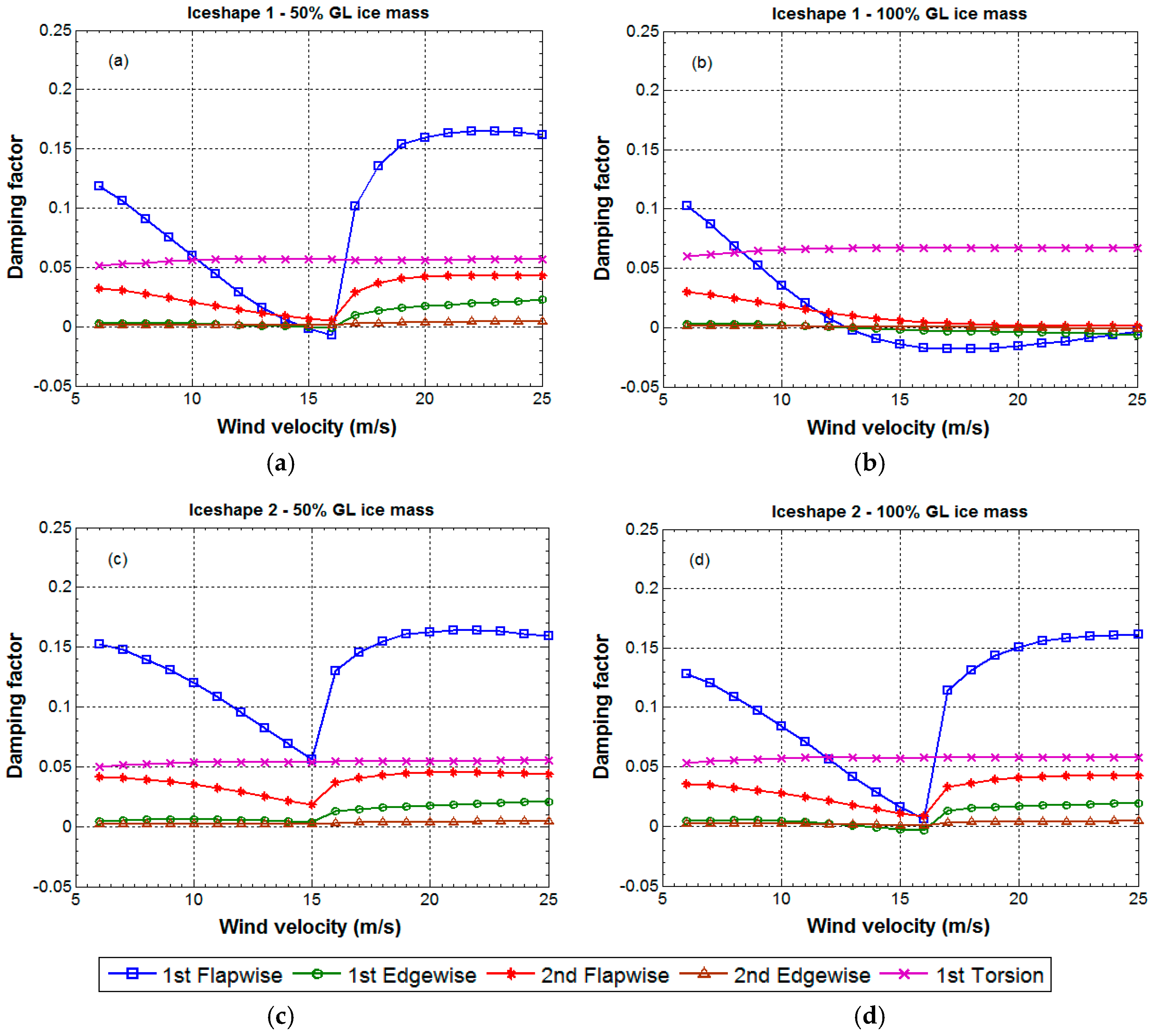
Table 2 with the frequencies of the blade without ice. Blade natural frequencies reduce about 5%–6% with 50% GL ice mass and about 9%–11% with 100% GL ice mass. The reduction in natural frequencies depends on how the ice mass is distributed along the blade. If aerodynamic changes are also considered along with the structural changes due to ice, natural frequency values don’t change significantly, but their damping factors vary significantly and can also lead to unstable vibrations (damping factors become negative). Aerodynamic loads contribute to damping in the aeroelastic equations of motion of the blade, which are highly affected by ice on the blades and modal damping factors of the blade change accordingly. Modal damping factors considering two ice shapes with 50% and 100% GL ice mass distributions are shown in
Figure 9. Flapwise modes of the blade are more damped when compared to the edgewise modes in the case of blade without ice (refer
Figure 6), but icing reduces damping factors of these flapwise modes. In the case of 100% GL ice mass with Ice shape 1, the damping factor of few modes becomes negative above 12 m/s wind velocity. In the case of Iceshape 2, the damping factor of few modes becomes negative over a small wind velocity range between 15 m/s and 17 m/s. Negative damping factor at these wind velocities would mean violent vibrations in the wind turbine blade if operated with ice.
The GL guideline only specifies the ice mass distribution along the blade and does not specify the ice shape. Either using simulation tools discussed in
Section 4 or from the images of iced blades, ice shapes on the blade can be obtained. These ice shapes can be replicated using the discrete Fourier sine series and their coefficients can be scaled to have the desired amount of ice mass on the blade as shown in this paper. In this paper, aerodynamic coefficients of the clean and iced aerofoils are calculated using JavaFoil (panel code), which only approximately estimates their aerodynamic behavior. The aerodynamic behavior of aerofoils is well predicted by panel codes in comparison to CFD at low angles of attack only. Panel codes are not able to accurately predict aerodynamic behavior at high angles of attack as the fluid flow separates from aerofoil surface, due to which lift force is over-predicted and drag force is under-predicted. The flow separation could be an issue for the irregular shapes of aerofoils in the case of rime ice, which can happen even at low angles of attack. JavaFoil over-predicts the aerodynamic coefficient curves and their slopes [
15]. We are not able to compare JavaFoil results of the iced aerofoils with other tools XFoil or XFLR5, as they did not converge for the distorted aerofoil shapes with ice. The aerodynamic behavior can only be compared with CFD simulations of the iced aerofoils and the authors plan this as a future work. In this paper, as we used JavaFoil for analyzing the aerodynamic behavior of both clean and iced aerofoils, the qualitative difference between them is still assumed to be true.
7. Summary and Conclusions
Partial differential equations governing the aeroelastic vibration behavior of the wind turbine blade are derived, which are then used to analyze the Tjaereborg 2 MW wind turbine blade vibrations using FEM. Two different ice shapes predicted in the literature are distributed according to GL specification on the blade and their influence on the blade natural frequencies and damping factors are investigated. Ice on the blade alters its structural properties (mass and inertia) and distortions in the aerofoil shapes affect its aerodynamic behavior. The aeroelastic changes in the blade due to ice affect its modal behavior as well as reducing turbine power output. Structural changes in the blade due to ice reduce its natural frequencies, whereas modal damping factors reduce according to the changes in aerodynamic behavior due to ice.
Out of the two ice shapes analyzed in this study, Ice shape 1 causes a greater drop in the power output compared to Ice shape 2 for the same amounts of ice mass. Under severe icing conditions (100% GL ice mass) with Ice shape 1, the damping factor of the first flap mode reduces more and becomes negative within the operating wind velocity range of this turbine, indicating the unstable vibration behavior of the blade. Ice leads to instability in the Tjaereborg wind turbine blade vibrations, which are otherwise stable without ice. If a greater drop in the power output is observed, along with reduction in blade natural frequencies during the turbine operation, it is required for safety to shut down the turbine and remove ice by starting deicing systems. In this study, the influences of smooth ice shapes on modal damping factors are investigated. However, a rough surface in the case of rime ice will have a different aerodynamic behavior causing a drastic drop in the turbine power output and modal damping. Thus, wind turbines for cold climates need to be robustly designed to withstand blade icing by evaluating their designs with various ice shapes and ice masses so that the limits of icing can be defined for the safe operation of the turbines.


