1. Introduction
Recently, the so-called dual-permanent-magnet-excited (DPME) machine has been proposed for low-speed large-torque direct drive applications [
1]. Unlike traditional permanent magnet (PM) machines, this unique machine employs two sets of PMs, one on the stator and the other on the rotor. It relies on the magnetic field harmonic components [
2,
3,
4,
5,
6] to achieve electromechanical energy conversion. The bi-directional field modulation effect (BFME) is artfully engaged to guarantee the effective coupling between the field harmonics excited by the armature windings and those excited by the two sets of PMs, so that stable electromagnetic torques can be produced. Due to the utilization of two sets of PMs, abundant field harmonic pairs can contribute to the generation of electromagnetic torque simultaneously. Therefore, this new type of machine is able to offer much higher torque capability than its traditional counterparts. Furthermore, since it is composed of only one rotor and one stator, its mechanical structure is much simpler than the existing integrated harmonic machines [
7,
8,
9,
10].
Previous study has demonstrated that, in coaxial magnetic gears [
11,
12,
13], the shape factors of the ferromagnetic segments have profound impacts on the field modulation effect and the transmitted torque capability [
14]. Meanwhile, decreasing the volume of the involved PM materials can definitely reduce the cost of the DPME machines and increase their competitiveness in commercial applications. Therefore, the purpose of this paper is to investigate the optimum design method for improving the BFME of DPME machines to further improve the pull-out torque of this new type of machine as well as reduce the usage of PMs. The design variables are introduced in
Section 2. Then, the optimum design using response surface methodology is elaborated on in
Section 3.
Section 4 is devoted to the results analysis. Finally, conclusions are drawn in
Section 5.
2. DPME Machine and Its Design Variables
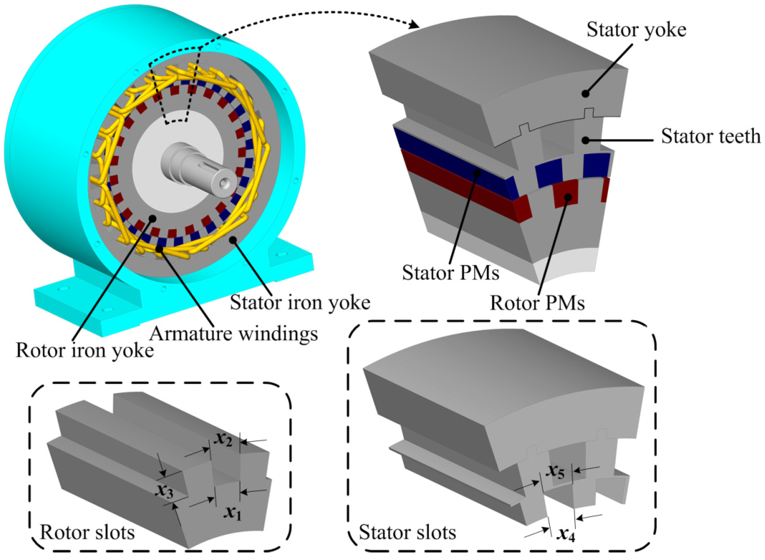
Figure 1 shows the configuration of the investigated DPME machine. Apparently, its mechanical topology is quite similar to that of the traditional rotary PM machines. The key difference lies in that the DPME employs two sets of PM poles: one is equipped on the rotor, and the other is equipped on the stator. In addition, the armature windings are also embedded in the stator. The two sets of PM poles are located beside the air-gap, while the armature windings are distributed on the periphery of the stator PM poles. In order to facilitate the assembly of the armature windings, the iron core on the stator is designed to be composed of two separate components, namely the stator yoke and the stator teeth, as shown in
Figure 1. The armature windings are wound on the stator teeth first. Then, the stator teeth with the windings are embedded into the stator yoke.
For the investigated DPME machine, the numbers of rotor PM poles and stator PM poles are equal to 23 and 27, respectively. Both the rotor PMs and stator PMs are outward-radially magnetized. It has been demonstrated that when all the PM poles are radially magnetized in exactly the same direction, the resulting DPME machine can exhibit outstanding performances [
15]. Each magnet and its adjacent iron tooth form a pair of magnet poles. Thus, the PM pole-pair numbers (PPNs) on the rotor and the stator are equal to 23 and 27, respectively. The three-phase armature windings are deployed in the 24 winding slots, and its PPN is equal to four. In summary, the detailed specifications of the investigated DPME machine are listed in
Table 1. All the PM poles are fabricated with bonded neodymium iron boron (NdFeB) materials. Such materials have significantly higher resistance than the sintered NdFeB materials. Therefore, the eddy current losses that occur in the PM poles caused by the varying magnetic field can be greatly suppressed. Moreover, the bonded NdFeB materials are convenient for shaped, and this is helpful for achieving their optimum design which will be elaborated on in the next section. The remanence and the coercive force of the PM poles are 0.8 T and 560 kA/m, and their intrinsic coercive force is as high as 1040 kA/m, which can guarantee that the PM poles will not be demagnetized by each other.
Figure 1.
Dual-permanent-magnet-excited (DPME) machine and its design variables.
Figure 1.
Dual-permanent-magnet-excited (DPME) machine and its design variables.
Table 1.
Specifications of investigated Dual-permanent-magnet-excited (DPME) machine.
Table 1.
Specifications of investigated Dual-permanent-magnet-excited (DPME) machine.
| Item | Value |
|---|
| Pole-pair number of armature windings | 4 |
| Pole-pair number of PMs on rotor/stator | 23/27 |
| Number of winding slots | 24 |
| Rated frequency | 50 Hz |
| Rated current density | 6 A/mm2 |
| Rate output torque | 120 Nm |
| Slot fill factor | 0.75 |
| Number of turns | 50 |
| Remanence of PMs (Br) | 0.8 T |
| Coercive force of PMs (Hc) | 560 kA/m |
| Intrinsic coercive force of PMs (Hci) | 1040 kA/m |
| Effective axial length | 90 mm |
| Length of air-gap | 0.6 mm |
| Outside radius of stator yoke/air-gap | 134.9/89.6 mm |
As shown in
Figure 1, five design variables,
x1,
x2,
x3,
x4 and
x5, are chosen for improving the BFME of the DPME machine, where
x1 and
x2 represent the width-angles in the circumferential direction of the inner-edge and the outer-edge of the rotor slots,
x4 and
x5 represent the width-angles in the circumferential direction of the inner-edge and the outer-edge of the stator slots, and
x3 represents the depth of the rotor slots. For the investigated machine, the outside radii of the stator yoke and the air-gap are 134.9 mm and 89.6 mm, respectively. In the following optimization process, these key sizes and the geometrical designs related to the armature windings are kept unchanged so that the overall volume of the investigated machine can be unchanged and the impacts of the windings can be ruled out. Therefore, the depth of the stator slots is kept as constant, which is equal to 10 mm for this investigated machine.
3. Design Optimization Using Response Surface Methodology
Response surface methodology (RSM) is a statistical technique for determining the best-fitted relationship between the design variables and the response [
16,
17,
18]. Herein, the second-order model is used to approximate the response function as,
where
Y denotes the pull-out torque of the investigated machine, β is the regression coefficient, and ε is the random error.
It is worth noting that a convention when using RSM is that the design variables xi, xj given in Equation (1) are the scaled values of their corresponding true values. Take the variable x1, for example. If we choose to let its value lie in the range of 4 degrees to 10 degrees, then the scaled value x1 = −1 is corresponding to the true value x1 = 4 degrees, the scaled value x1 = 1 is corresponding to the true value x1 = 10 degrees, and the scaled value x1 = 0 is corresponding to the true value x1 = 7 degrees.
Since the RSM is not able to handle cases with more than four variables very well, the optimum process is conducted in two steps. Firstly, the shape of rotor slots concerning variables x1, x2, and x3 is considered. After that, the shape of stator slots concerning variables x4 and x5 is taken into account. Central composite design (CCD) is applied to construct the samples to be investigated and the finite element method (FEM) is engaged to calculate the pull-out torques of the samples.
Table 2 lists the 15 samples and their calculated pull-out torques in the first step. These samples are chosen according to the laws of CCD. They represent the typical cases that are located on the surfaces and the center of the space extended by the design variables. That is why this method is named response surface methodology.
The least-squares method is used to estimate the unknown regression coefficients, and the fitted model concerning (
x1,
x2,
x3) can be obtained:
where the scaled values as listed in
Table 2 are adopted for the values of (
x1,
x2,
x3).
Table 2.
Experiment results using central composite design (CCD) for optimizing rotor slot.
Table 2.
Experiment results using central composite design (CCD) for optimizing rotor slot.
| | (x1, x2, x3) [Unit: Deg., Deg., mm] | Pull-Out Torque [Unit: Nm] |
|---|
| True value/Scaled Value | True Value | Fitted Value |
|---|
| 1 | (10,12,15)/(1,1,1) | 98.97 | 104.68 |
| 2 | (10,12,3)/(1,1,−1) | 129.23 | 126.64 |
| 3 | (10,4,15)/(1,−1,1) | 67.04 | 64.80 |
| 4 | (10,4,3)/(1,−1,−1) | 90.67 | 87.16 |
| 5 | (4,12,15)/(−1,1,1) | 143.02 | 146.24 |
| 6 | (4,12,3)/(−1,1,−1) | 133.66 | 135.60 |
| 7 | (4,4,15)/(−1,−1,1) | 61.04 | 63.34 |
| 8 | (4,4,3)/(−1,−1,−1) | 59.10 | 53.10 |
| 9 | (7,8,15)/(0,0,1) | 144.31 | 135.32 |
| 10 | (7,8,3)/(0,0,−1) | 131.05 | 141.19 |
| 11 | (7,12,9)/(0,1,0) | 145.05 | 136.76 |
| 12 | (7,4,9)/(0,−1,0) | 66.13 | 75.57 |
| 13 | (10,8,9)/(1,0,0) | 133.25 | 135.88 |
| 14 | (4,8,9)/(−1,0,0) | 141.09 | 139.63 |
| 15 | (7,8,9)/(0,0,0) | 144.56 | 142.24 |
The analysis of variance (ANOVA) [
19] is engaged to examine the effectiveness of the fitted model. The results are listed in
Table 3. It can be seen that the coefficient of determination is 0.972, while the adjusted coefficient of determination equals 0.922. This means that the fitted model indicated by Equation (2) can offer a good accuracy.
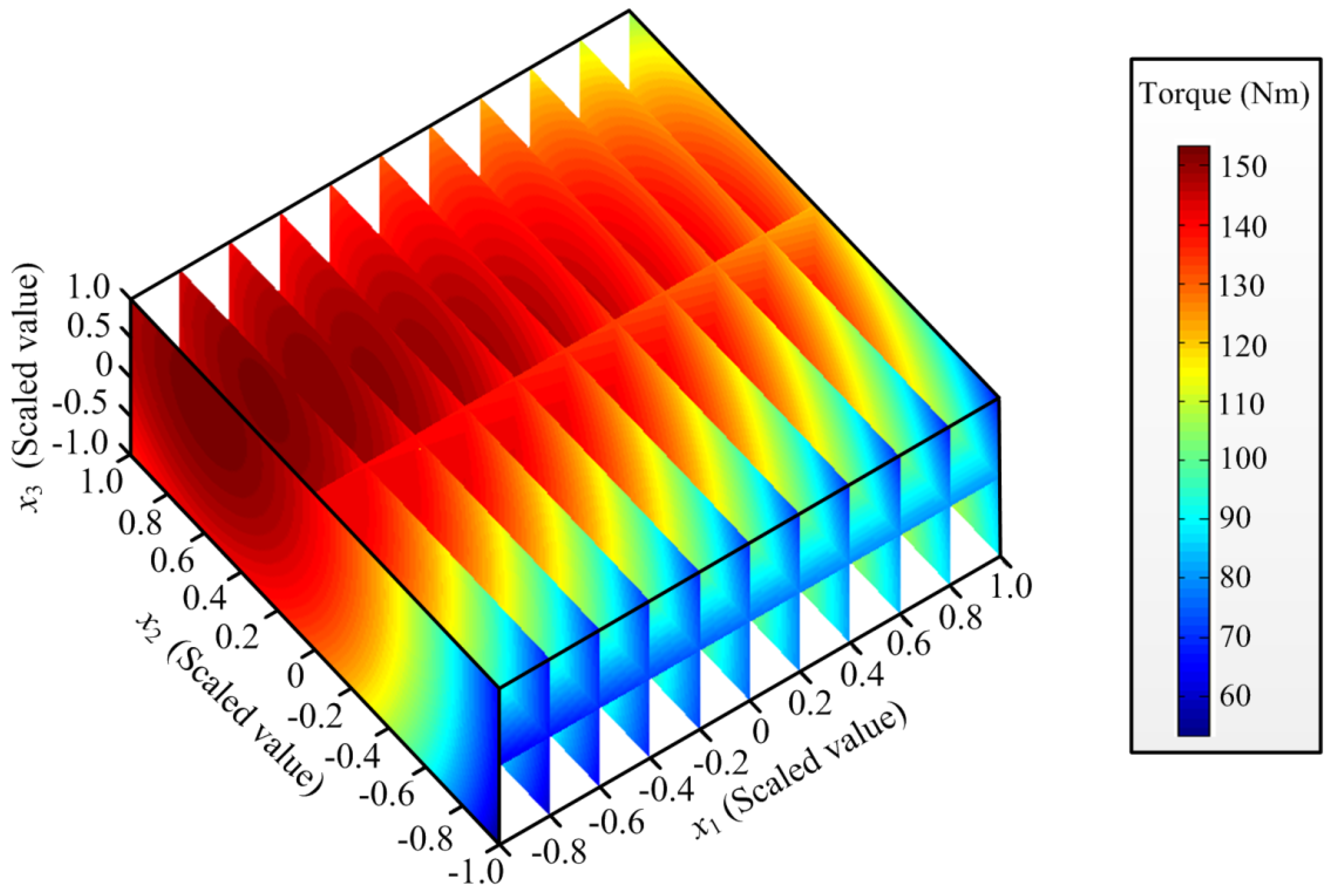
Figure 2 shows the responses of the fitted model in the first step. The optimum solution is
x1 = 4.000 degrees,
x2 = 10.296 degrees,
x3 = 12.966 millimeters, and the resulted pull-out torque equals 153.2 Nm. These results will be kept unchanged in the next step when searching for the optimal solutions of the design parameters concerning the stator slot.
Table 3.
Analysis of variance for optimizing rotor slot.
Table 3.
Analysis of variance for optimizing rotor slot.
| Source | Regression | Residual | Total |
|---|
| Degree of Freedom | 9 | 5 | 14 |
| Sum of Squares | 16259.8 | 467.7 | 16727.4 |
| Mean Square | 1806.6 | 93.5 | – |
| F-Statistic | 19.3 | – | – |
| Coefficient of Determination | 0.972 | – | – |
| Adjusted Coefficient of Determination | 0.922 | – | – |
Figure 2.
Responses of fitted model concerning (x1, x2, x3).
Figure 2.
Responses of fitted model concerning (x1, x2, x3).
In the second step, seven samples are selected to determine the best-fitted function between the stator slot shape factors and the pull-out torque of the DPME machine.
Table 4 lists the calculated pull-out torques by using FEM. Similarly, the least-squares method is used to estimate the unknown regression coefficients, and the fitted model concerning (
x4,
x5) can be obtained:
where the scaled values as listed in
Table 4 are adopted for the values of (
x4,
x5).
Table 5 lists the analyzed results obtained from ANOVA. The coefficient of determination is 1.000, while the adjusted coefficient of determination equals 0.998. This means that the fitted model indicated by Equation (3) can offer a very good accuracy.
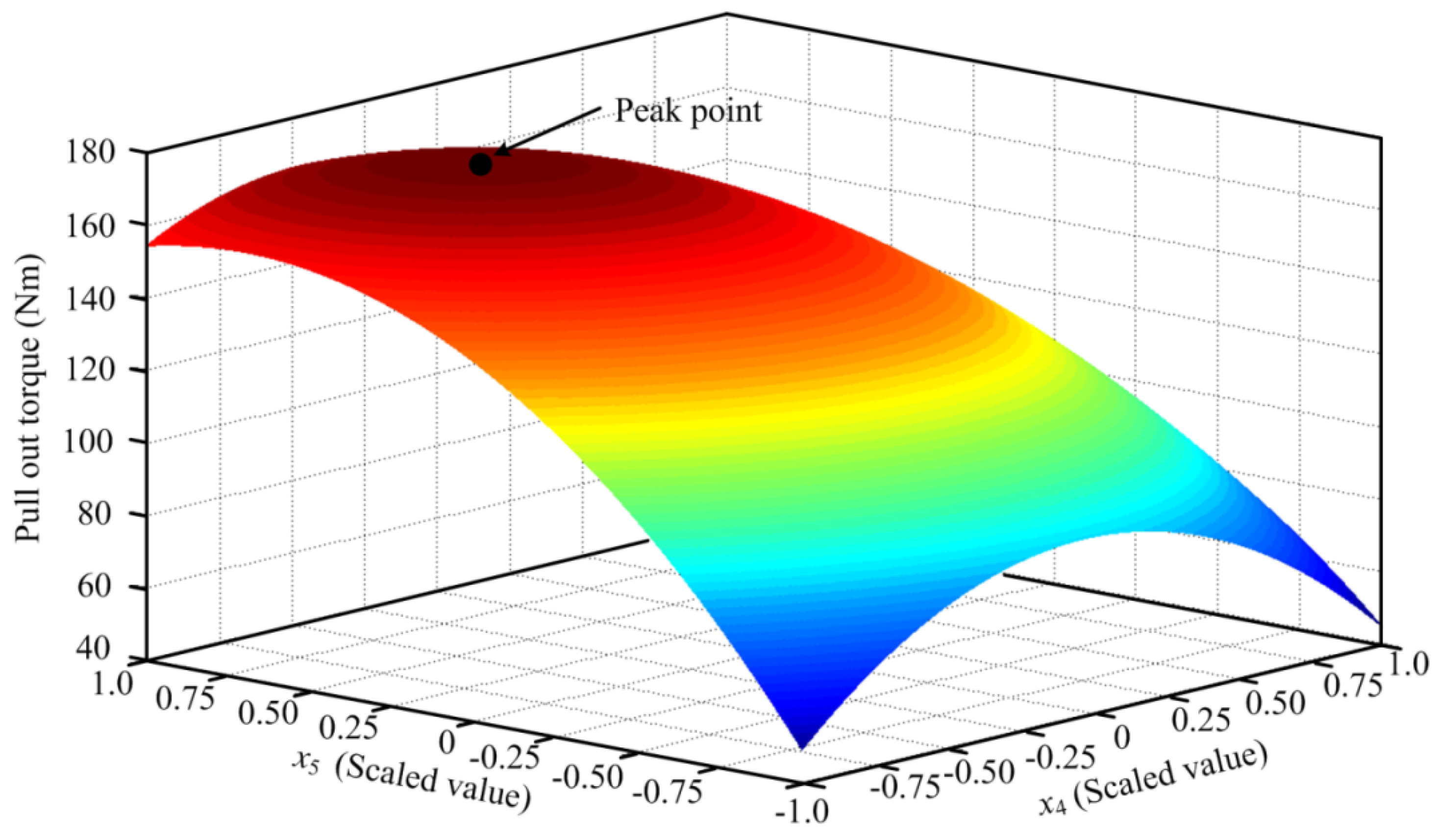
Figure 3 shows the responses of the fitted model in the second step. The optimum solution is
x4 = 9.970 degrees,
x5 = 5.860 degrees, and the resulted pull-out torque is equal to 173.2 Nm.
Table 4.
Experiment results using CCD for optimizing stator slot.
Table 4.
Experiment results using CCD for optimizing stator slot.
| | (x4, x5) [Unit: Deg., Deg.] | Pull-Out Torque [Unit: Nm] |
|---|
| True Value/Scaled Value | True Value | Fitted Value |
|---|
| 1 | (12,12)/(1,1) | 75.90 | 76.56 |
| 2 | (12,3)/(1,−1) | 45.34 | 44.67 |
| 3 | (3,12)/(−1,1) | 153.35 | 154.01 |
| 4 | (3,3)/(−1,−1) | 49.70 | 49.04 |
| 5 | (7.5,12)/(0,1) | 158.32 | 157.00 |
| 6 | (7.5,3)/(0,−1) | 87.24 | 88.56 |
| 7 | (7.5,7.5)/(0,0) | 160.05 | 160.05 |
Table 5.
Analysis of variance for optimizing stator slot.
Table 5.
Analysis of variance for optimizing stator slot.
| Source | Regression | Residual | Total |
|---|
| Degree of Freedom | 5 | 1 | 6 |
| Sum of Squares | 15982.5 | 5.2 | 15987.8 |
| Mean Square | 3196.5 | 5.2 | – |
| F-Statistic | 610.1 | – | – |
| Coefficient of Determination | 1.000 | – | – |
| Adjusted Coefficient of Determination | 0.998 | – | – |
Figure 3.
Responses of fitted model concerning (x4, x5).
Figure 3.
Responses of fitted model concerning (x4, x5).
Up until now, the optimum case (x1 = 4.000 degrees, x2 = 10.296 degrees, x3 = 12.966 millimeters, x4 = 9.970 degrees, x5 = 5.860 degrees) of the investigated DPME machine has been obtained. Its performance will be assessed in the next section.
4. Performance Analysis
Two-dimensional (2D) FEM is engaged to compare the initial machine design (case 1) and the optimum machine design (case 2). In the initial case, the rotor slot has the same width-angle in the circumferential direction as its adjacent rotor teeth, which means
x1 =
x2 = 7.826 degrees, and the depth of the rotor slots means
x3 = 10 millimeters. Furthermore, the stator slot is also has the same width-angle in the circumferential direction as its adjacent stator teeth, which implies
x4 =
x5 = 6.667 degrees. The comparison of design variables between the initial case and the optimum case is listed in
Table 6.
Table 6.
Comparison of design variables between initial case and optimum case.
Table 6.
Comparison of design variables between initial case and optimum case.
| Design Variables | Initial Case | Optimum Case |
|---|
| x1 [Degree] | 7.826 | 4.000 |
| x2 [Degree] | 7.826 | 10.296 |
| x3 [mm] | 10.000 | 12.966 |
| x4 [Degree] | 6.667 | 9.970 |
| x5 [Degree] | 6.667 | 5.860 |
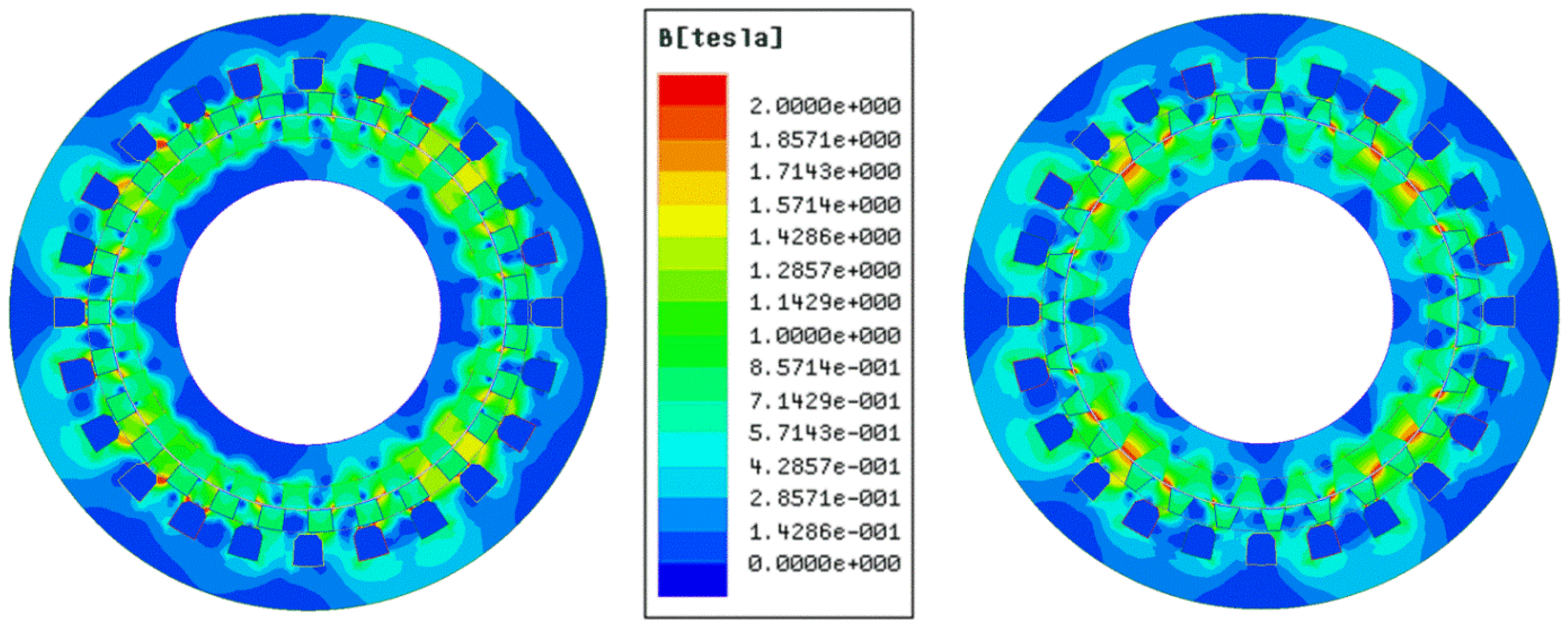
Figure 4 illustrates the flux density distribution at no load in the two cases. It can be observed that there exists magnetic saturation in the tips of the iron teeth beside the air-gap of the optimum case. Although it is not desired in machine design, sometimes it might be acceptable as long as it does not affect the overall performance of the machine.
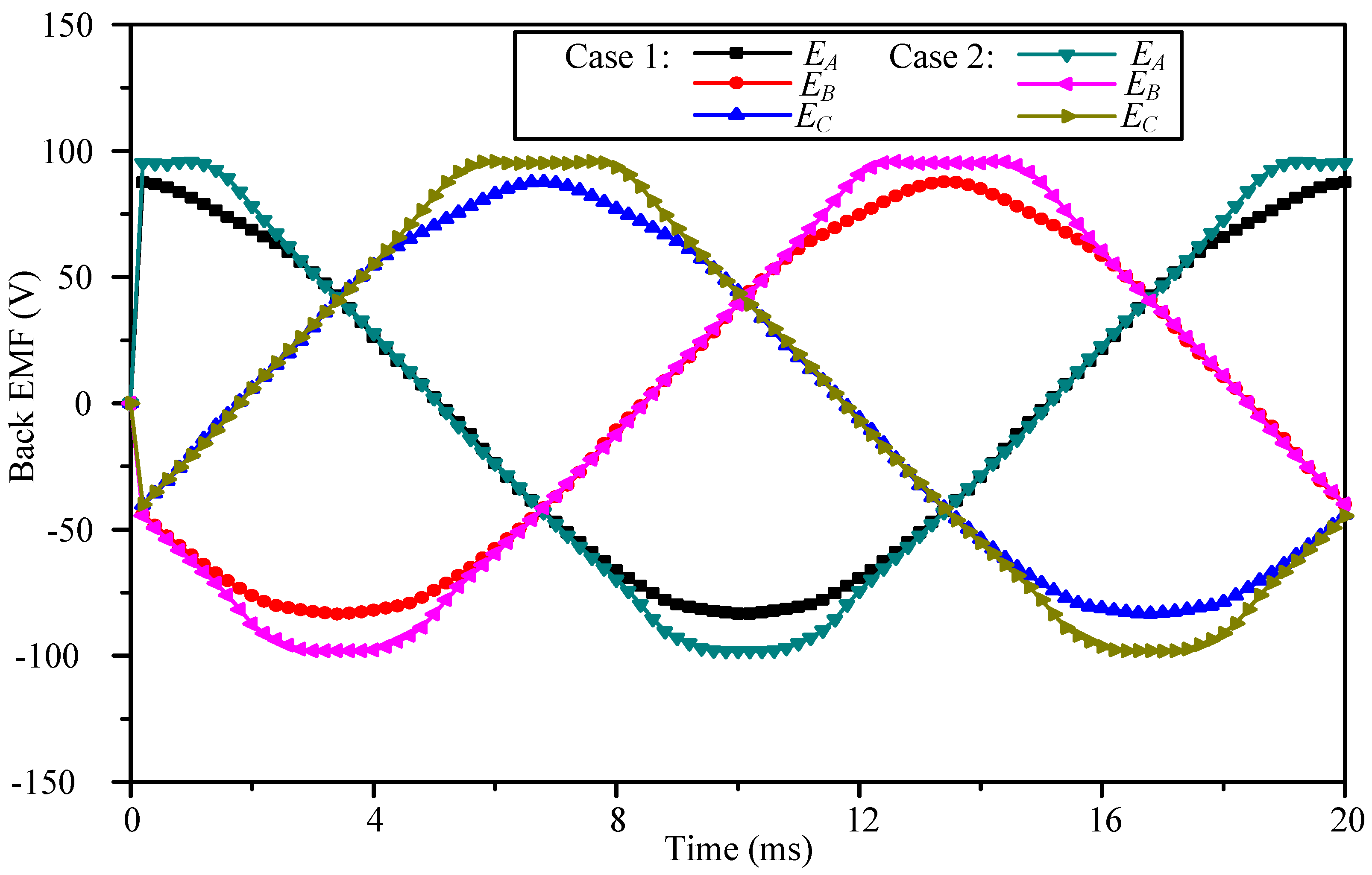
Figure 5 gives the waveforms of back electromotive force (EMF) generated by the two machines when rotating at the rated speed. It can be observed that the peak value which results in the optimum case is 100 V, which is about 20% higher than that which results in the initial case.
Figure 4.
Flux density distribution in the initial case (left) and the optimum case (right) at no load.
Figure 4.
Flux density distribution in the initial case (left) and the optimum case (right) at no load.
Figure 5.
Comparison of back electromotive force (EMF).
Figure 5.
Comparison of back electromotive force (EMF).
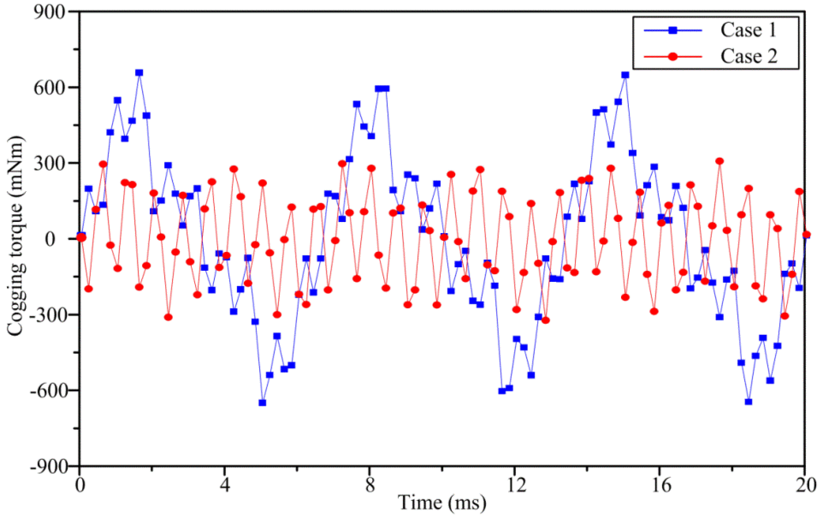
Figure 6 illustrates the cogging torques of the two machines. It can be found that the optimum design can help reduce the peak value of the cogging torque.
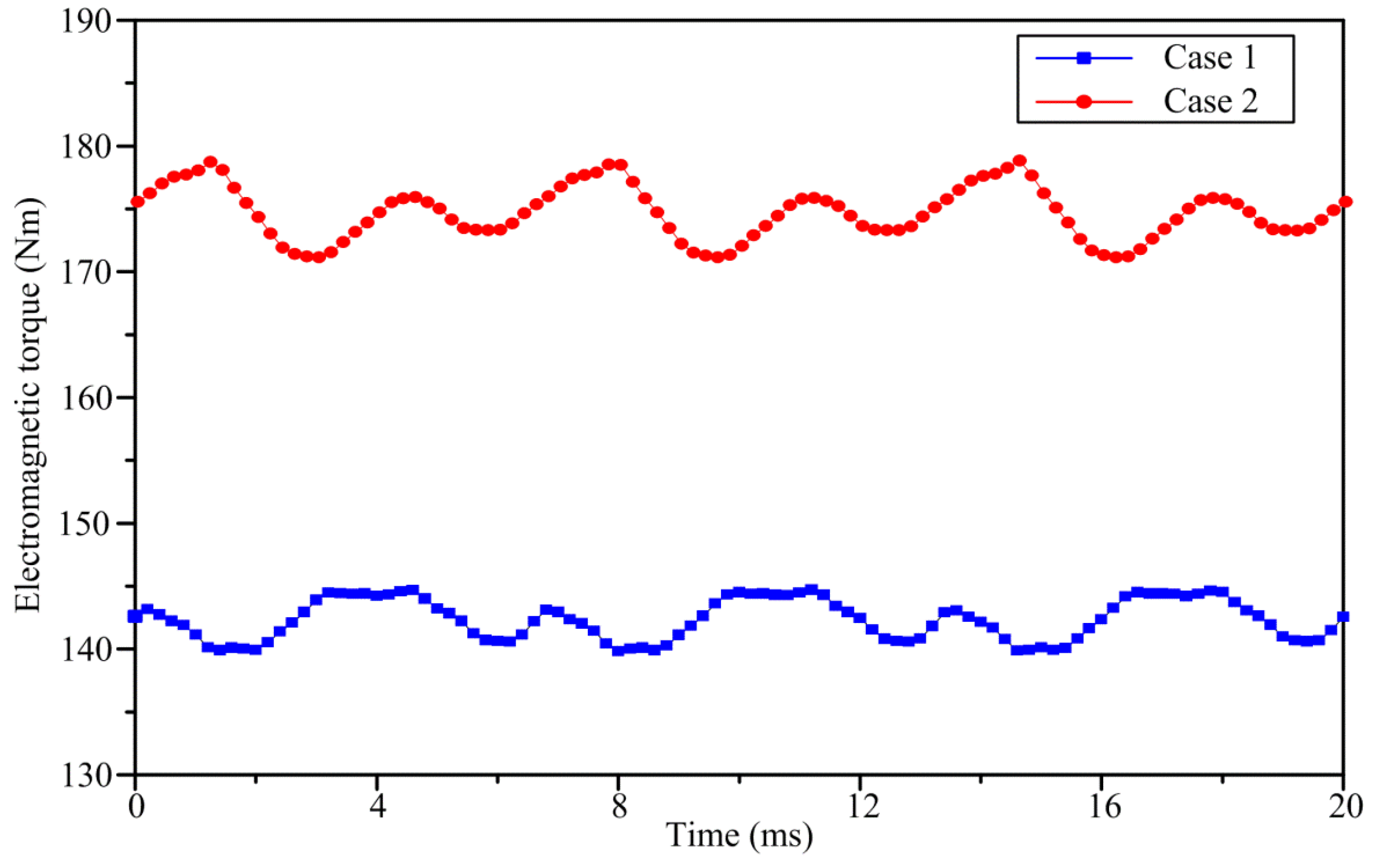
Figure 7 gives the resulted pull-out torque-time curves on the rotor of the two machines produced by exactly the same armature currents. The injected current density
J is equal to 6 A/mm
2. It can be observed that average values of pull-out torque in the two cases are 141.9 Nm and 176.6 Nm, respectively. This means that by optimizing the slot shape, the torque capability of the investigated DPME can be improved by 24.5%. It also can be observed that the torque ripple in the optimum case is a little bit larger than that in the initial case. The reason is that the injected currents are standard sinusoidal ac currents, while the resulted back EMF waveform is not that sinusoidal in the optimum case. It is well known that the torque ripples can be suppressed by adjusting the waveforms of the armature currents.
Figure 6.
Comparison of cogging torques.
Figure 6.
Comparison of cogging torques.
Figure 7.
Comparison of pull-out torques.
Figure 7.
Comparison of pull-out torques.
It is worth noting that the volume of PM material involved in the optimum case is decreased by 8.9% compared with that involved in the initial case. This demonstrates that the bi-directional modulating effect has been greatly improved since the torque capability is increased with reduced usage of PM materials.
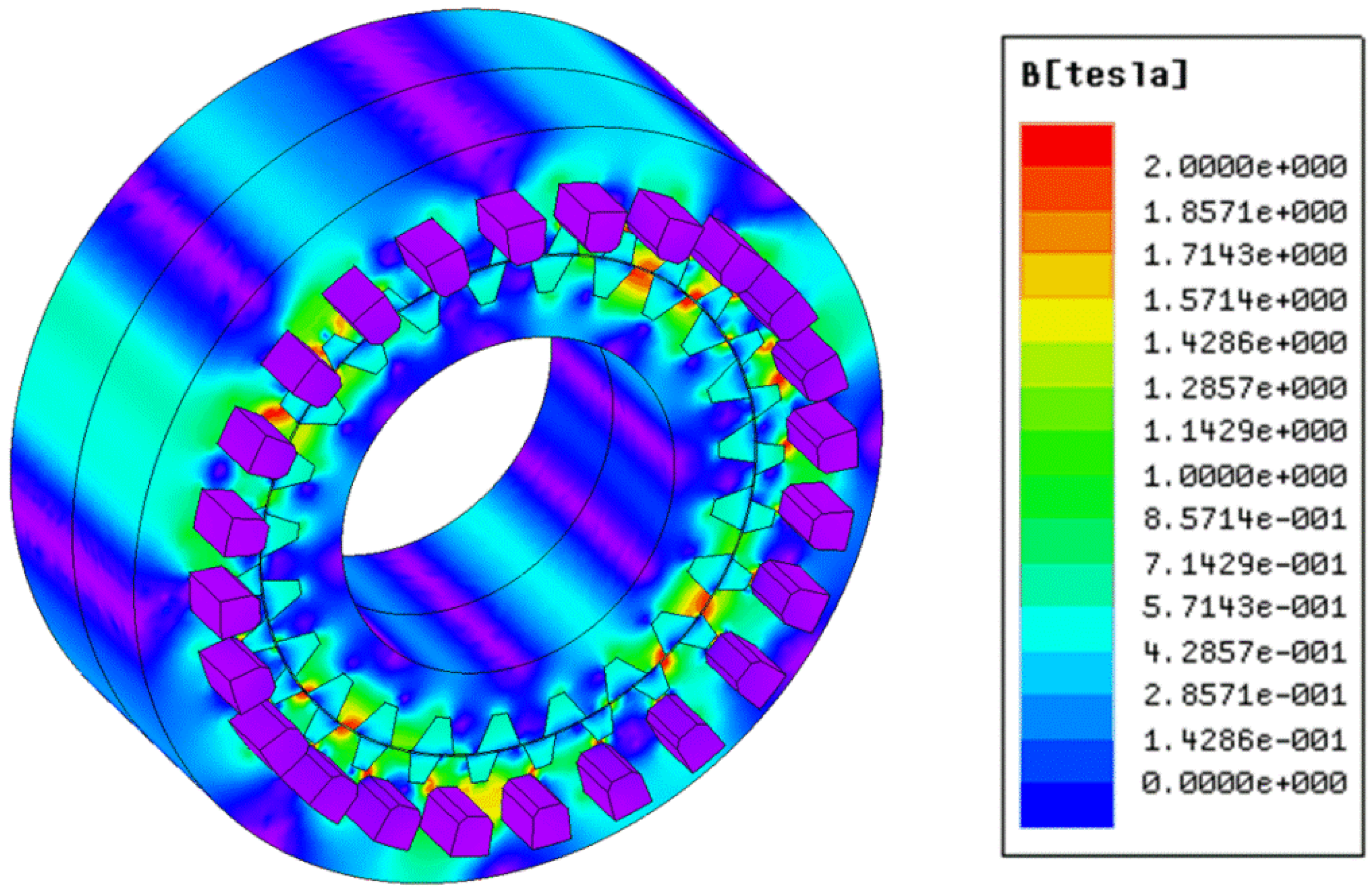
It is well known that the end effect of PM machines may deteriorate their torque capability. In order to investigate the end effect of the optimum case, its three-dimensional (3D) model is built up by using 3D FEM, and the resulting 3D flux density distribution is illustrated in
Figure 8. Also, by injecting armature currents (
J = 6 A/mm
2) into the windings, the pull-out torque can be obtained as 154.2 Nm. It is about 12.7% less than the result obtained by using the 2D model.
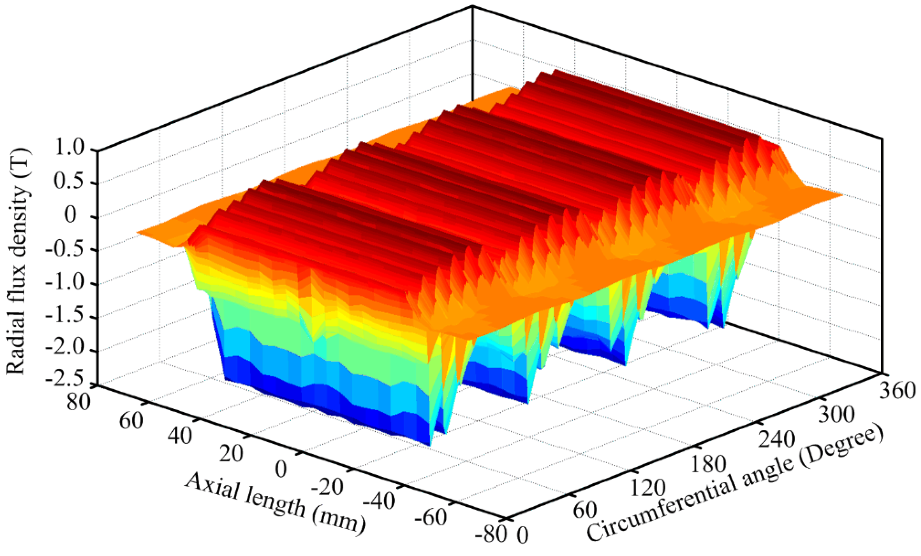
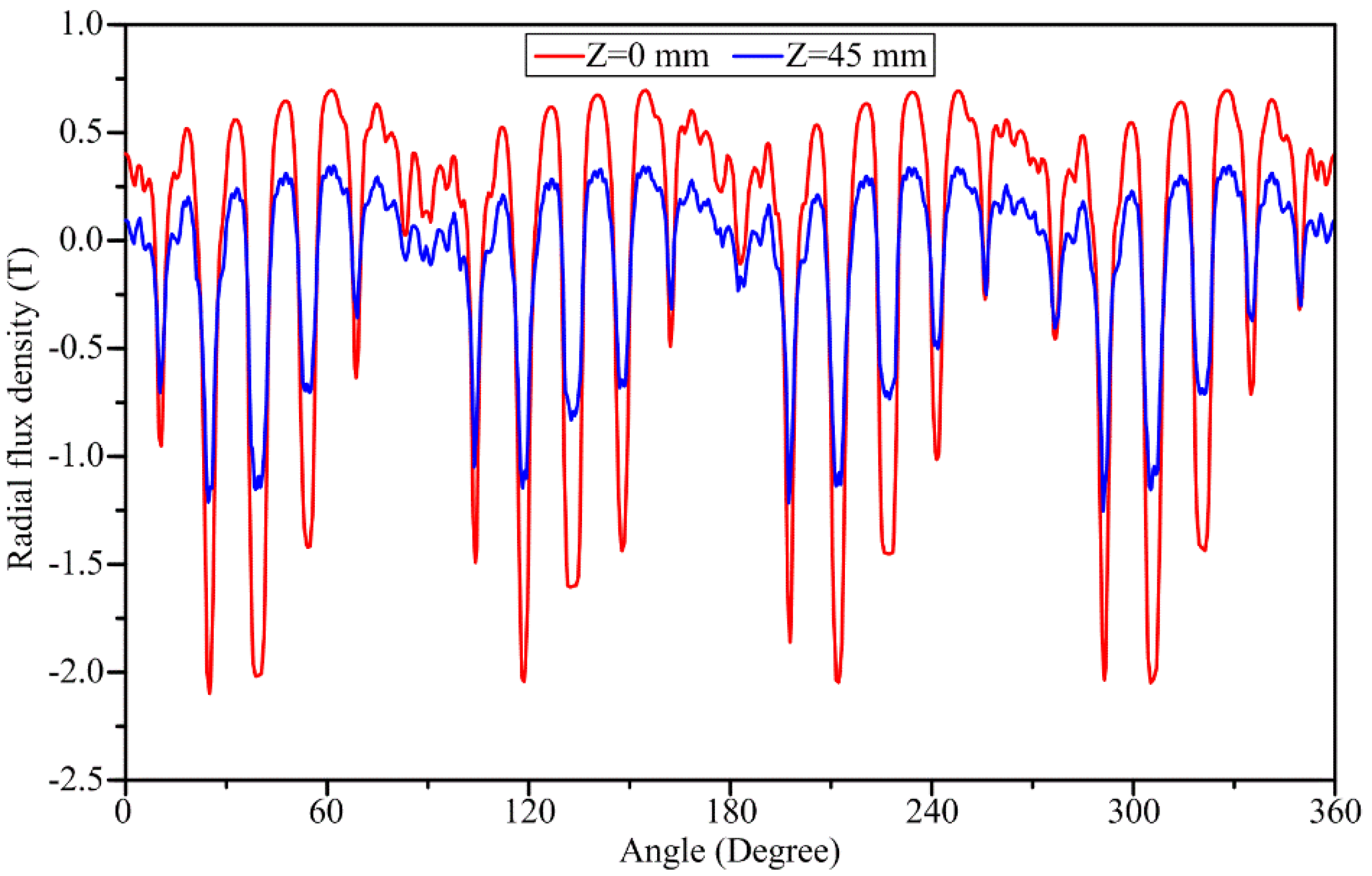
Figure 9 illustrates the 3D radial flux density in the air-gap. It can be observed that the flux density attenuates at the regions near the two axial ends, and there exists leakage flux in the adjacent air space. In order to make it easier to understand, the 2D plots of the radial flux density in the different axial positions are illustrated in
Figure 10. It can be observed that the magnitude of the flux density in the middle of the axial direction (Z = 0 mm) is much stronger than that in the edge of the axial direction (Z = 45 mm).
Figure 8.
Three-dimensional (3D) flux density distribution in optimum case.
Figure 8.
Three-dimensional (3D) flux density distribution in optimum case.
Figure 9.
Three-dimensional radial flux density in the air-gap in the optimum case.
Figure 9.
Three-dimensional radial flux density in the air-gap in the optimum case.
Figure 10.
Two-dimensional (2D) radial flux density in the air-gap in the optimum case.
Figure 10.
Two-dimensional (2D) radial flux density in the air-gap in the optimum case.
Finally, the iron losses occurred in the iron cores are estimated by using FEM. Although it remains a large challenges for the accurate calculation of iron loss in electric machines [
20,
21], we are still able to make a comparison between the initial case and the optimum case, and calculate the iron loss in the one which is bigger than that in the other, by using numerical calculations. The classical method to calculate iron loss is given by the following Bertotti’s equation [
20]:
where
Pe,
Ph,
Pa are the eddy current loss, the hysteresis loss, and the anomalous loss, respectively;
Ke,
Kh,
Ka are the coefficients of eddy current loss, hysteresis loss, and anomalous loss; and
f and
B are the frequency and amplitude of the magnetic flux density.
Unfortunately, for the DPME machines, there are lots of varying field harmonic components in the iron cores and Bertotti’s equation cannot work very well. One method is to conduct Fourier decomposition first, then calculate the iron loss arising from each field component by using Bertotti’s equation, and sum up these results to obtain the whole iron losses. This method is very inefficient and its accuracy is also insufficient [
22]. To counter this problem, Bertotti’s equation can be transformed from frequency domain into time domain, and therefore, the following calculation model can be derived:
where Δ
Bi represents the amplitudes of the minor hysteresis loops, and
Nl is the number of the minor hysteresis loops.
Table 7 lists the calculation results of the iron losses of the two machines at rated speed (130 rpm) and with rated current (
J = 6 A/mm
2). It can be found that the iron losses occurred in the optimum case are slightly bigger than that occurred in the initial case. It is quite understandable considering that the magnetic field has been strengthened and the torque capability has been improved in the optimum machine. The estimated copper loss in the windings is equal to 83.6 W. The output electromagnetic torques of the initial machine and the optimum machine are 124.9 Nm and 154.2 Nm. Thus, the output powers of the initial machine and the optimum machine are 1699 W and 2098 W, and their efficiencies are 94.1% and 95.1%, respectively. It means that although the iron losses occurred in the optimum machine are slightly higher than that in the initial machine, its efficiency is also higher due to the improved output power.
Table 7.
Comparison of iron losses between initial case and optimum case at rated speed.
Table 7.
Comparison of iron losses between initial case and optimum case at rated speed.
| | Initial Case | Optimum Case |
|---|
| Rotor core | Pe | 1.5 W | 1.8 W |
| Ph | 0.4 W | 0.5 W |
| Pa | 6.0 W | 6.9 W |
| Stator core | Pe | 2.7 W | 3.1 W |
| Ph | 11.2 W | 12.0 W |
| Pa | 0.9 W | 1.0 W |
| Total iron losses | 22.7 W | 25.3 W |


