1. Introduction
The prediction of centrifugal compressor efficiency and operating range is essential to maintain the gas production sustainability and machine availability and to reduce the operating cost. There are several external process parameters that affect the centrifugal compressor in the operating environment. These factors can introduce a significant impact on the compressor characteristics which in turn influence the compressor efficiency and aerodynamic stability. Testing the new machine performance at the field conditions will help to evaluate the design specifications prior to the installation process. However, the actual suction parameters might be different than that tested by the manufacture, so the test results have to be correlated with the actual conditions. Moreover, predicting abnormal compressor performance and aerodynamic issues of the running machines at an early stage can help to avoid catastrophic failures or mandatory shut downs.
Schultz [
1] developed a polytropic model to predict compressor performance based on ideal and real gas correlations. Mallen and Saville [
2] found that the assumed polytropic path function in this method was only accurate at lower pressure levels so they proposed an alternate path function and accompanying analysis. On the other hand, the conducted comparison analysis by Huntington [
3] revealed a larger percentage of error in the obtained results by Mallen and Saville [
2] method. One of the main disadvantages of these two approaches is the fact that some of the stated assumptions are only applicable for ideal gas conditions. Furthermore, these two models are based on the fact that the stage efficiency is a function of the process gas properties only without considering the impact of Mach number and flow coefficient.
Another alternative approach to derive the compressor performance at off-design conditions is by using the existing correction factors. This method is used extensively in the open literature due to its simplicity such as Lapina [
4], Kurzke
et al. [
5], C. Kong
et al. [
6], and Santinelli [
7]. However, this technique does not consider the change in the gas properties which can introduce a higher degree of uncertainty while dealing with hydrocarbons. To address this issue, this method has been modified by ASME PTC-10 [
8] in order to correct the test results and with a consideration of the gas properties variation. This report introduced only the instructions to carry out the mentioned correction without developing a systematic approach to implement it. Moreover, the proposed guidelines require a large set of data and meter readings which are practically not available without conducting a machine test. Sandberg
et al. [
9] reported some issues with the accuracy of the predicted parameters using this approach in high pressure applications and especially with high carbon dioxide percentages, including the stage efficiency and polytropic head.
Yuanyuan
et al. [
10] proposed another methodology which basically depends on the transformation of the real operating parameters to specific reference conditions. This method was developed basically assuming that the polytropic efficiency is independent on the thermodynamic parameters and with a constant density ratio. However, it is important to mention here that both methods [
8,
10] address only a single flow and rotational speed values and without considering the entire compressor map.
This paper will propose a new iterative, systematic method to derive the equivalent centrifugal compressor performance at various suction conditions and gas compositions. One of the unique features of the derived model is the fact that it can be used to derive the overall compressor performance map at different operating conditions from the reference point. Furthermore, the variation in the stage efficiency and gas properties are considered including the density ratio, and with less dependency on the test data. Unlike the existing models, the efficiency is obtained as a function of gas composition, suction conditions, Mach number, and flow coefficient leading to more precise prediction of performance parameters.
This paper is structured in three main sections. The first part describes the basics of the derived method and the phases of the established methodology. This is followed by an example to test the validity of the new approach to predict the centrifugal compressor performance at various suction pressures and temperatures. The final part of this paper investigates and models the effect of suction pressure and temperature on the stag efficiency and compressor stability. This optimization will help the user to determine the contribution of these factors on the compressor instability. A further case is presented in the second part of this study in order to emphasize the validity of this method with various gas compositions.
2. Description of the Method
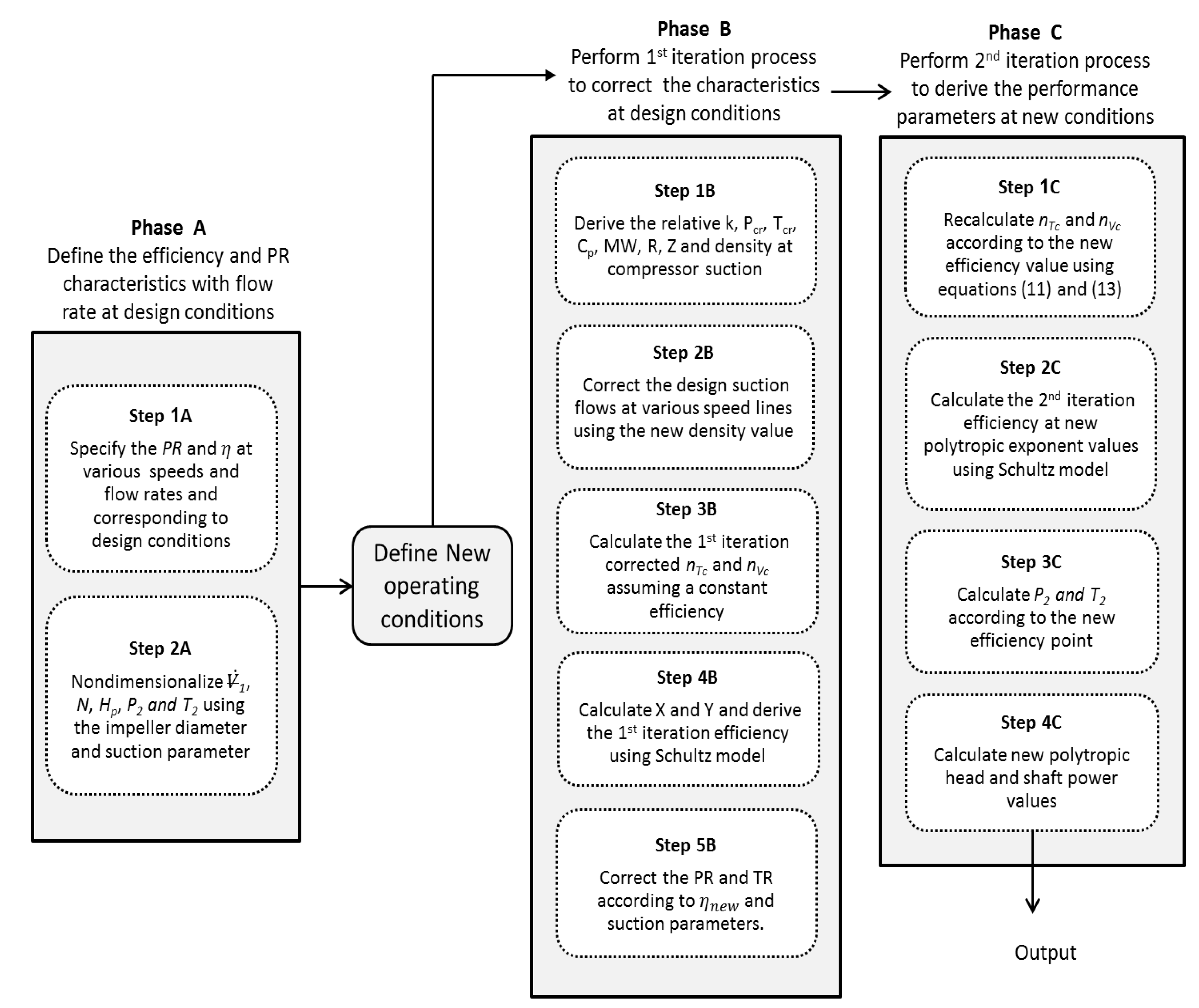
The proposed method in this paper is based on the fact that the compressor performance parameters can be determined based on the suction parameters, physical properties of the process gas, Mach number, and flow and work coefficients. The influence of these factors on the stage performance characteristics vary significantly based on the compressor design and gas compositions. Accordingly, the developed approach can be divided into three main phases as illustrated in
Figure 1:
Define the compressor performance characteristics at design conditions in terms of discharge pressure and temperature corresponding to various flow coefficients and Mach numbers.
Use the new suction conditions to derive the equivalent inlet gas properties which are then used to correct the design flow rates based on the new operating conditions. The efficiency and the discharge conditions are determined initially based on the first iteration polytropic exponent () and compressibility functions ( and ).
Recalculate the polytropic exponents and the compressibility functions based on the obtained efficiency using the Lüdtke equations of polytropic temperature and volume exponents [
11]. Thus, the new values are then used again to determine the relative efficiency and discharge conditions by Schultz model [
1].
At constant speed operation, the global flow coefficient (φ) can be defined in terms of suction volume flow, exit impeller diameter, and tip speed. To derive the flow rate at new operating point, the flow coefficient is assumed to be constant at that particular speed. Additionally, the tip speed and impeller diameter are fixed at the specified rotational speed and impeller geometry.
Figure 1.
Scheme of developed method.
Figure 1.
Scheme of developed method.
The performance parameters at design conditions are considered as reference points in this method to obtain the equivalent characteristics at new suction conditions. The gas constant (
) can be written in term of molecular weight. Thus, the Equation (1) yields to the following final correlation (2):
The compressibility factor () is determined as a function of the gas composition and suction pressure and temperature using equations of state or generalized compressibility charts.
The derived Equation (2) can be used to correct the design flow rate at new operating point in terms of suction gas parameters and the design flow rate. The gas properties can be considered at the suction side or as an average value. However, the same approach should be followed for both reference and off-design conditions.
In order to determine the pressure ratio at the new operating point, Equation (4) can be used. According to Casey-Robinson work coefficient model [
12], the work coefficient (
) is only a function of impeller geometry and flow coefficient (
). Thus, at fixed flow coefficient and rotating speed, the impeller work coefficient has to be constant.
When there is a change in the suction flow rate, the work coefficient is no longer constant. Accordingly, the new work coefficient () is obtained using Equation (5) where the correlation coefficients (,) are determined by matching the work coefficient value at design point operation.
Furthermore, the speed of sound is the only factor that influences the Mach number when such impeller is rotating at the same speed. Hence, the new pressure ratio value equation can be expressed in terms of design pressure ratio, gas properties and polytropic efficiency.
In order to calculate the polytropic efficiency, Schultz polytropic exponent equation [
1] is used.
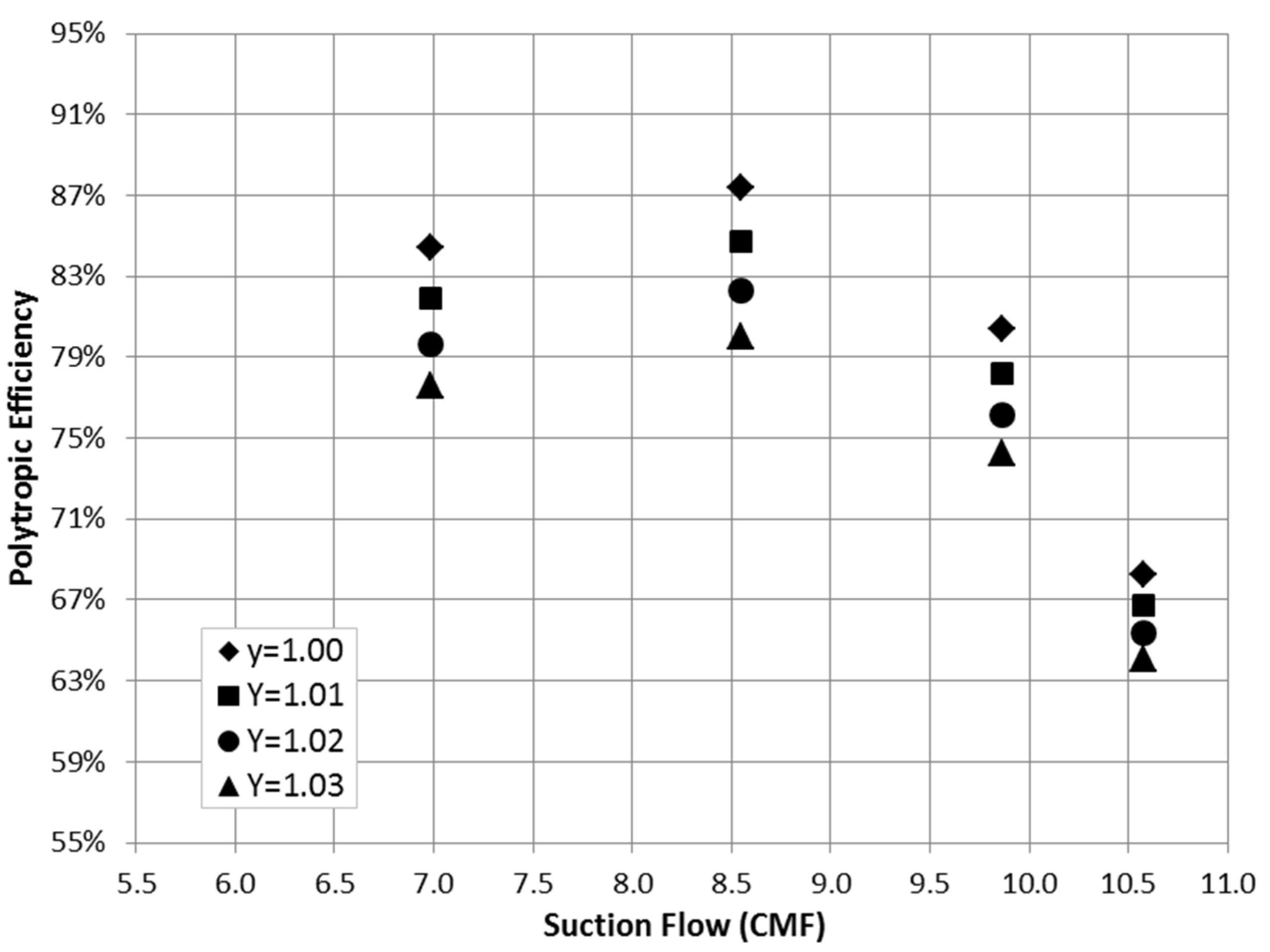
The compressibility functions (
) can be determined graphically in terms of reduced pressure (
) and temperature (
). However, rounding the corresponding
X and
Y variables can introduce a small deviation from the actual value which has a significant impact on the determined efficiency value as demonstrated in
Figure 2.
Figure 2.
Effect of compressibility function (Y) on polytropic efficiency.
Figure 2.
Effect of compressibility function (Y) on polytropic efficiency.
To avoid that, the values of X and Y are obtained using the Equations (8) and (9).
Despite that these two correlations are derived by approximating some terms, the developed method is dealing with the ratio of the
X and
Y values at reference and off-design conditions. Thus, the effect of this approximation can be ignored. By rearranging Equation (7), the polytropic efficiency can be determined using the following formula:
This equation determines the efficiency as a function of gas properties only. Hence, a further iteration will be performed to correct the obtained value based on the flow coefficient and Mach number. As the first iteration, the temperature polytropic exponent () is derived assuming a constant efficiency using Equation (11). This correlation is derived from the basic temperature polytropic exponent Equation (12).
Thus, the volume polytropic exponent () is calculated from Formula (13) in terms of temperature exponent () and gas properties.
The calculated polytropic exponent value is substituted in Equation (10) to determine the first iteration efficiency at new operating conditions. Accordingly, this efficiency value is used to derive the resultant pressure ratio by applying Equation (6). Thus, the initial overall discharge pressure and temperature can be calculated.
The obtained efficiency and discharge parameters are acceptable for the first approximation but, to achieve more accurate results, a second iteration process is performed using the obtained parameters from the first trial. The calculated polytropic efficiency is used to obtain the temperature polytropic exponent in Equation (11) and the volume exponent by Equation (13). Accordingly, a new polytropic efficiency value is determined using Equation (10) and the relative discharge pressure and temperature are recalculated. The derived discharge parameters are expected to be closer to the actual values as the constant efficiency assumption is no longer valid. Respectively, the polytropic head () is calculated using Equation (15). This correlation has been derived from the basic polytropic head Equation (14).
When there is a change in the flow coefficient from the design values, a further step is taken to correct the determined efficiency based on the new work coefficient value.
The total shaft power is obtained assuming a constant rate of the aerodynamic and mechanical losses at the specified rotating speed and flow coefficient.
3. Developed Method Validation
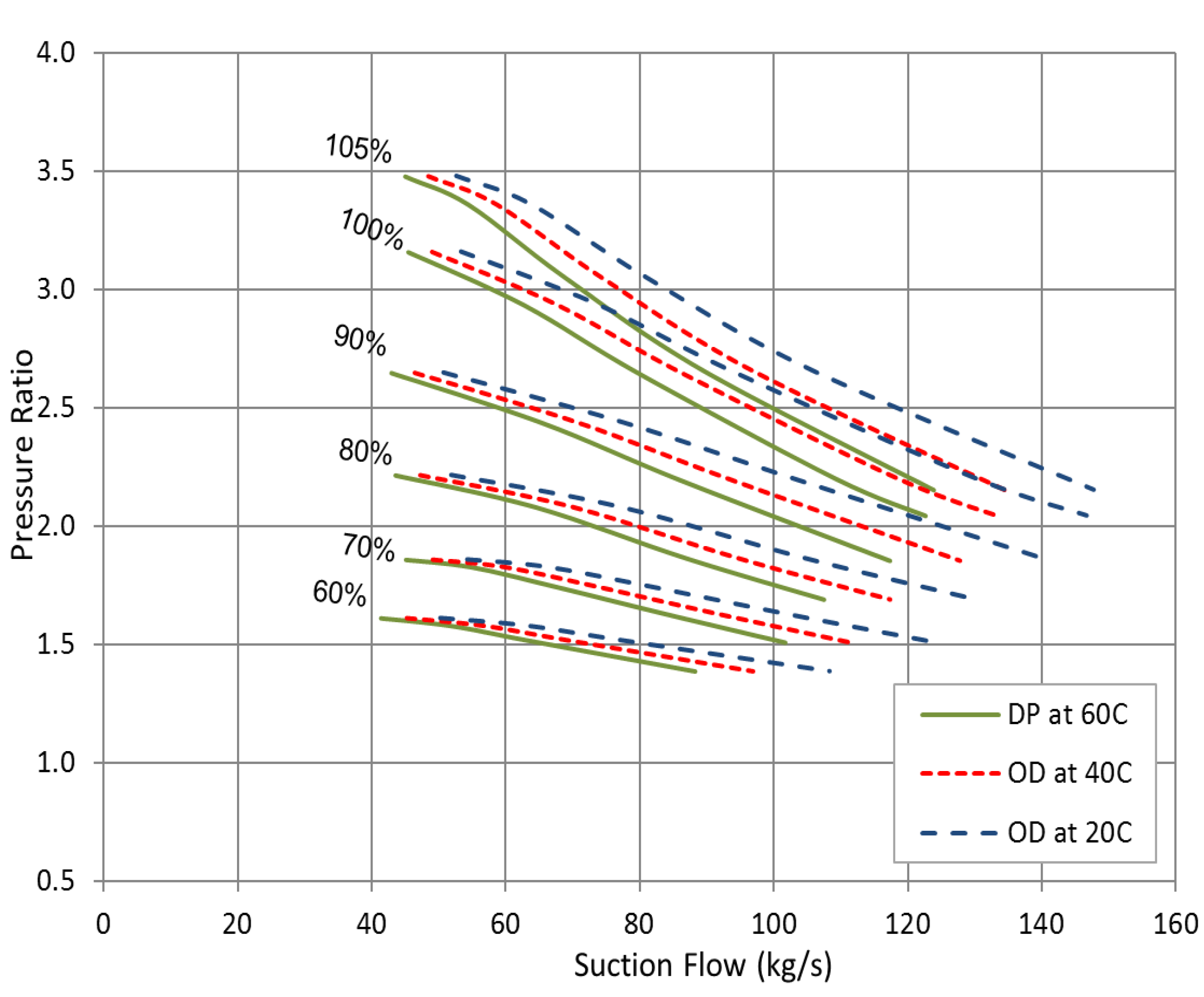
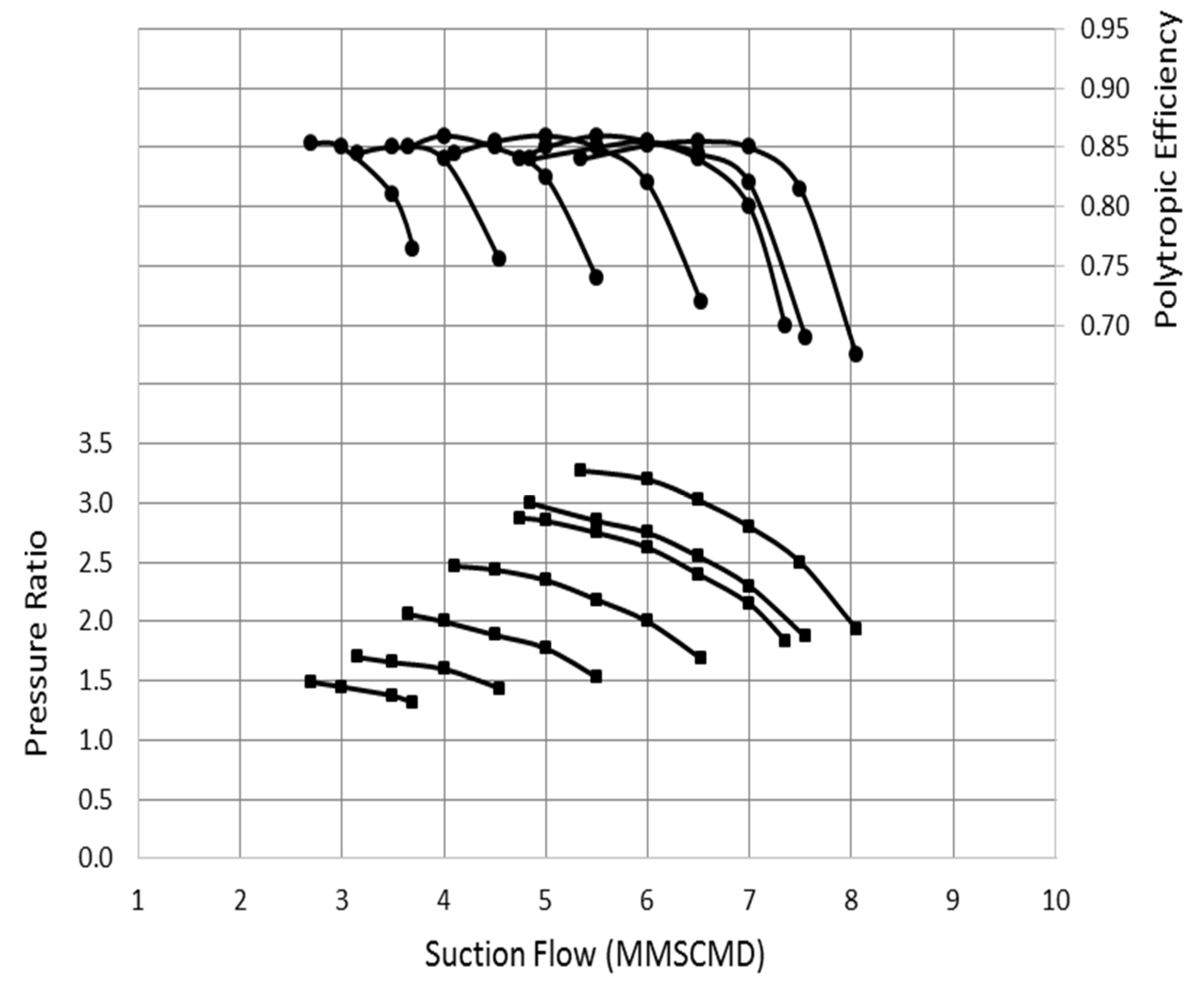
In order to test the validity of the developed approach, it is implemented to predict the equivalent performance of a gas lift centrifugal compressor driven by 14.5 MW electric motor. The design point operation requires 21 bara at the compressor discharge with an inlet volume flow of 6 MMSCMD (Million Metric Standard Cubic Meter per Day) and suction pressure of 8 bara. The gas is a hydrocarbon mixture and the design point performance was derived at 51 °C inlet temperature as illustrated in
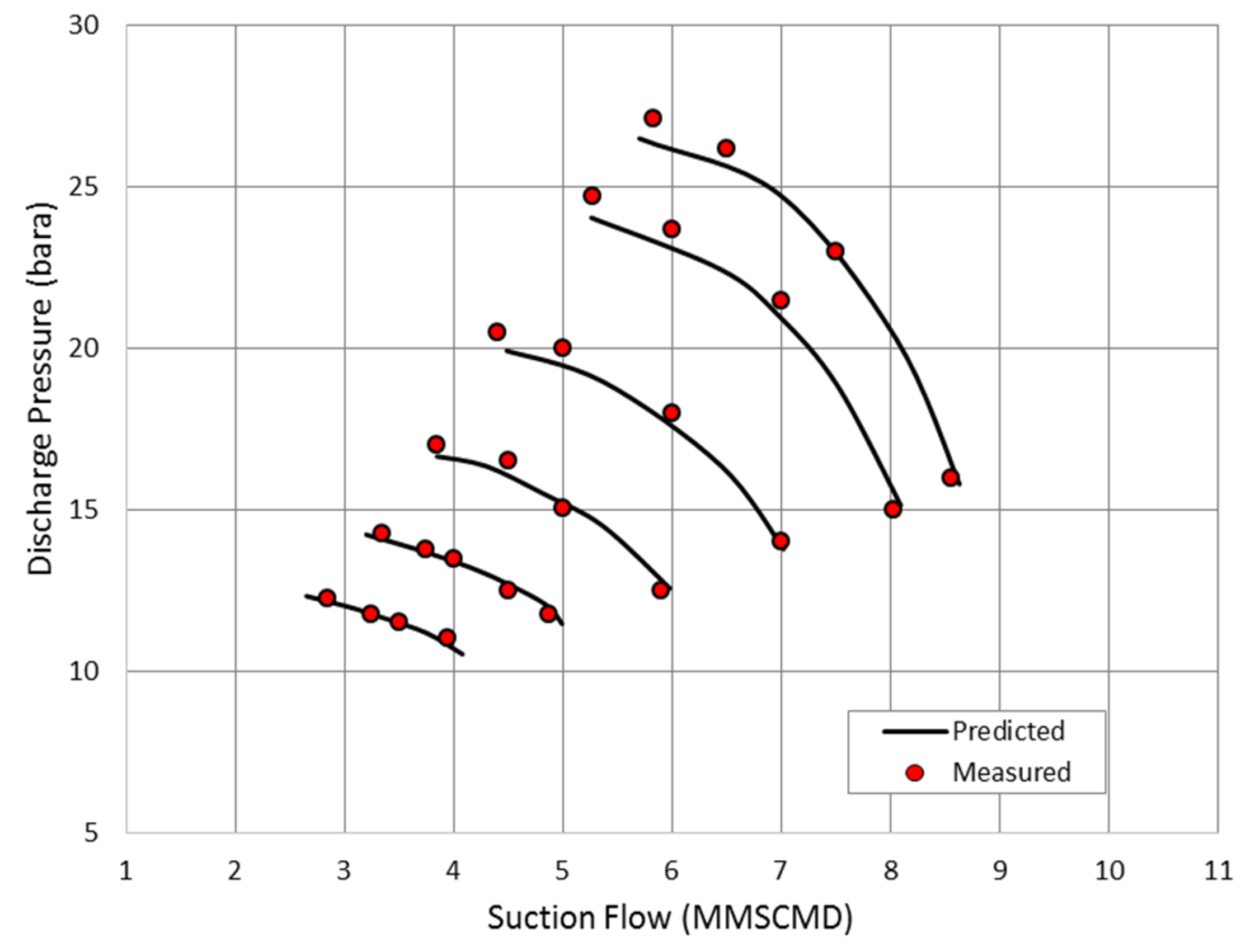
Figure 3. However, the compressor is expected to run at various inlet temperatures ranging from 20 to 55 °C. The developed methodology was followed to derive the equivalent compressor performance at inlet temperature of 34 °C and suction pressure of 8.10 bara. The derived discharge pressures are plotted against the measured data as shown in
Figure 4.
Figure 3.
Derived performance curve based on measured discharge pressure and efficiency.
Figure 3.
Derived performance curve based on measured discharge pressure and efficiency.
Figure 4.
Comparison between the predicted and measured discharge pressure.
Figure 4.
Comparison between the predicted and measured discharge pressure.
The derived curve shows a good matching with actual values especially at low flow rates. There is a slight increase in the measured discharge pressure at the surge point comparing with the predicted values. This deviation is clearly increasing at high speed operation. The largest percentage of error was observed near the surge pressure of 105% speed line with approximately 2.21%, which is still acceptable. The rise in the measured discharge pressure at high speed is most properly caused by the reduction in the associated pressure losses at low inlet temperature. Besides, the predicted surge and choke flows were found very close to the measured data at all speed lines. The lower suction temperature and the higher inlet pressure push the pressure ratio to shift towards higher value than the design pressure driven by density reduction.
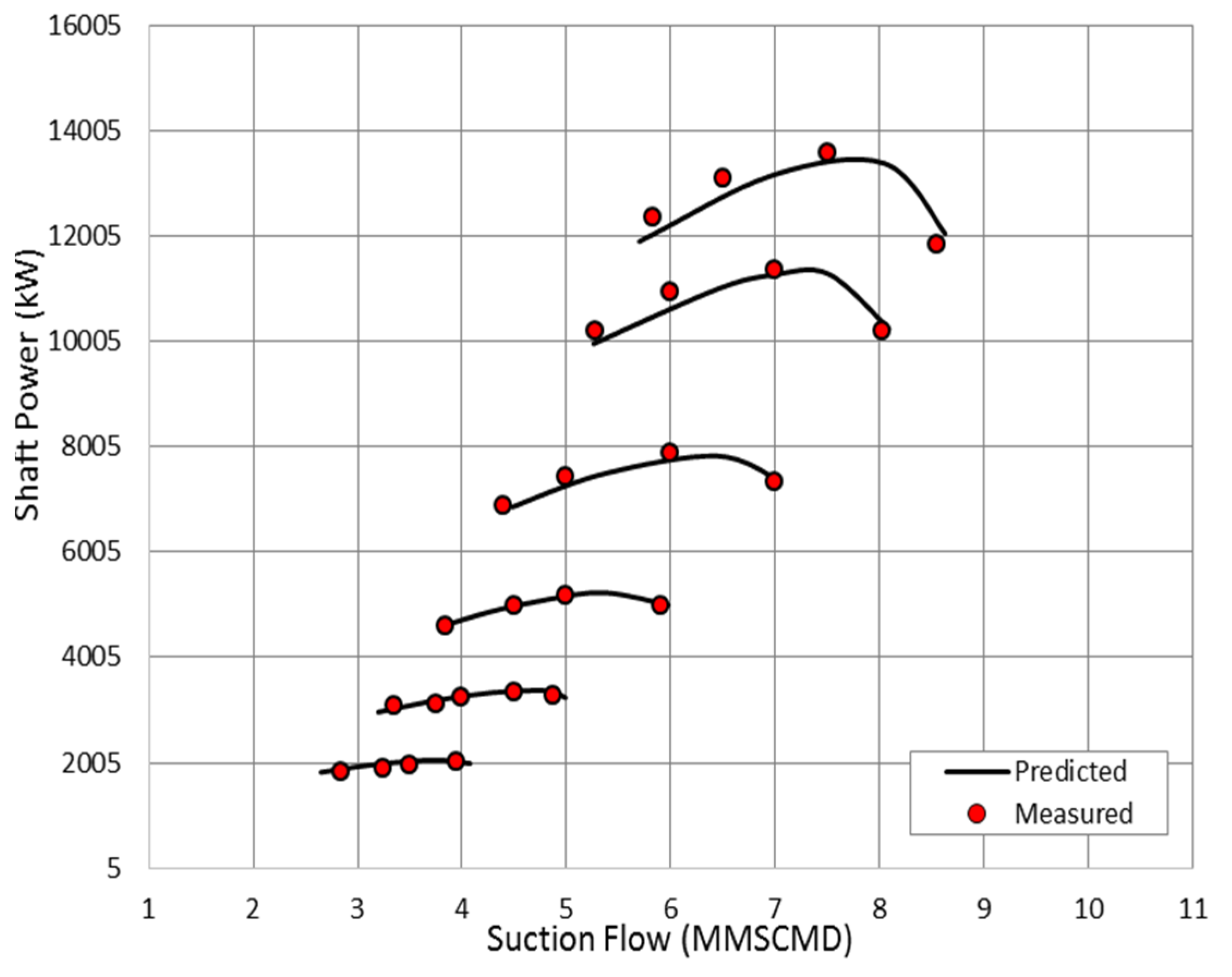
The power curve in
Figure 5 demonstrates that most of the measured points fall on the constant speed lines. However, the higher measured pressure ratio near the surge point of high Mach number operation yields to a slight increase in the measured power. As the speed goes down, the deviation between the measured and estimated power decreases gradually.
Figure 5.
Comparison between the predicted and measured shaft power.
Figure 5.
Comparison between the predicted and measured shaft power.
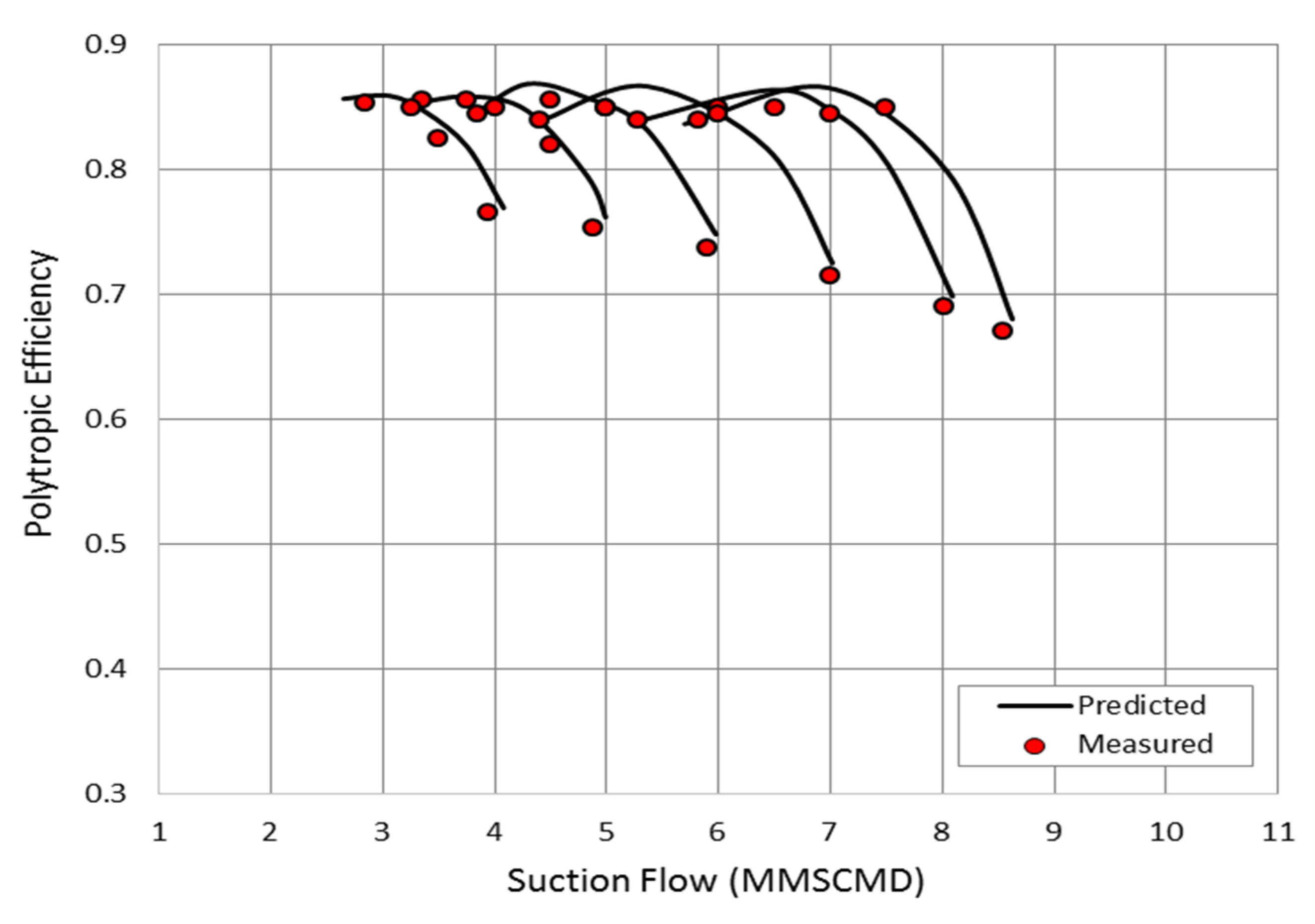
Figure 6 compares between the predicted and measured efficiencies at various suction flows and rotational speeds. The measured efficiencies are obtained at the measured pressure ratios and shaft power which illustrated in
Figure 4 and
Figure 5. Despite the increase in the measured pressure ratio and shaft power near the surge point, the relative efficiency matches the predicted value with insignificant difference. The greatest percentage of error was found near the choke point of the 105% speed line by about 1.49%. This value is greatly under the 5.0% allowed deviation, which obviously emphasizes the validity of the derived method.
Figure 6.
Comparison between the predicted and measured polytropic efficiencies.
Figure 6.
Comparison between the predicted and measured polytropic efficiencies.
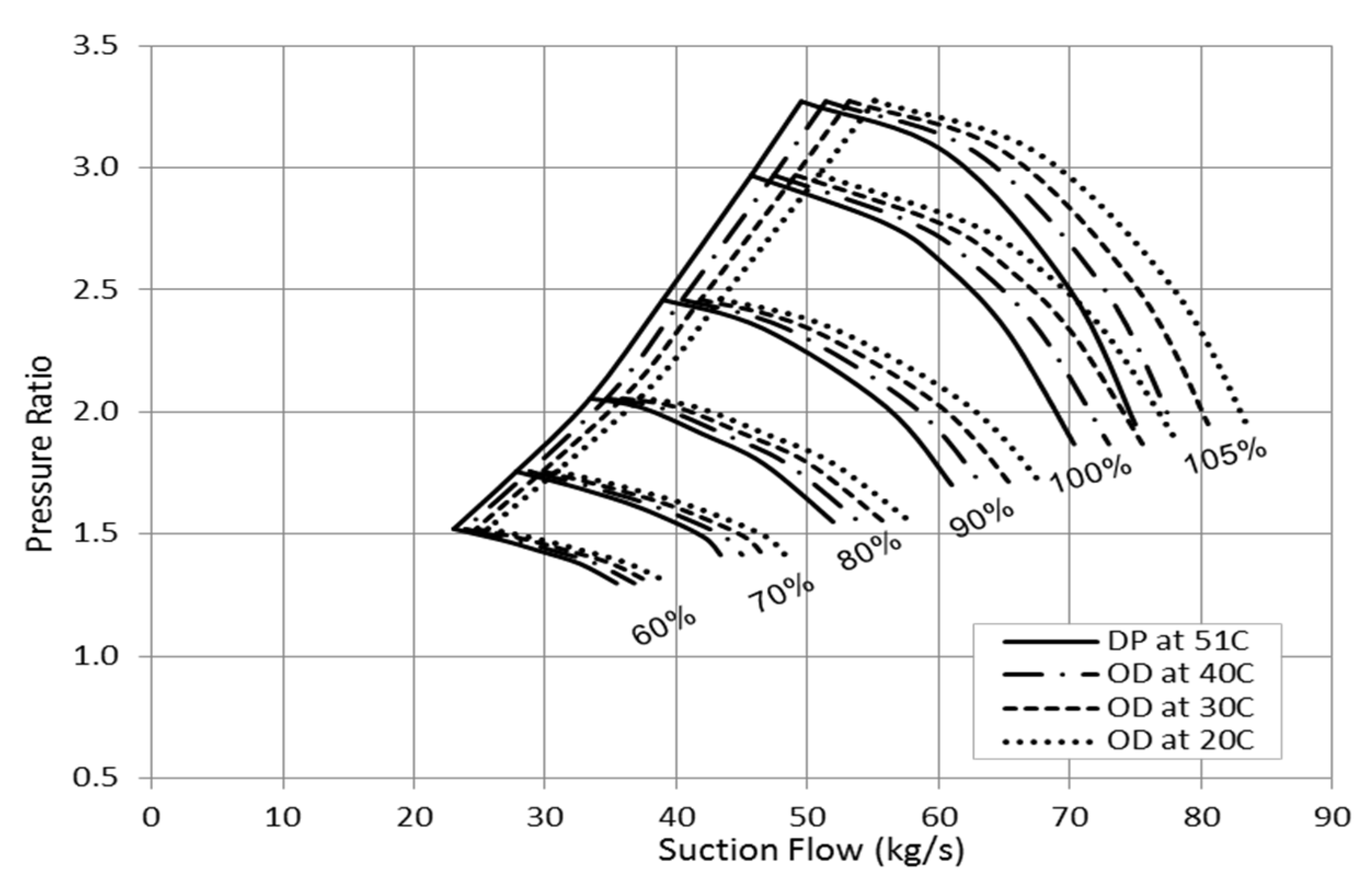
4. Significance of Suction Temperature
Figure 7 shows a rise in the compressor pressure ratio as the gas temperature drops. The incremental increase in the discharge pressure at constant suction pressure varies based on the rotational speed and the suction flow. However, the influence of suction temperature becomes more significant as the compressor flow starts approaching the stonewall point.
Figure 7.
Effect of suction temperature on the compressor pressure ratio.
Figure 7.
Effect of suction temperature on the compressor pressure ratio.
When there is a variation in the process temperature, more noticeable fluctuation in the discharge pressure can be observed at high flow rate operation. A steeper reduction in the pressure ratio was found at high suction temperature as the flow approaches the choke point. Additionally, the discharge pressure difference is greater at high rotational speed. Accordingly, it is recommended at such temperature variation conditions to avoid running the compressor at very high flow rates and rotational speeds in order to reduce the induced vibration level.
At constant rotational speed and suction flow, the surge margin is reduced further and further in response to the suction temperature drop. This causes the pressure ratio of low inlet temperature curves to decline at greater suction flow yielding to smaller deviation in pressure ratio values at low capacity rates. When a constant discharge pressure is targeted, the compressor speed has to be reduced as the suction temperature decreases. Two basic gas properties contribute in the discharge pressure rise, which are the compressibility factor (Z) and ratio of specific heats (k). The variation in these two parameters are, relatively, very small for air process so it can be ignored but it is not the case for other gases in which their variation impact can be proven to be significant. The molar heat capacity is taking a non-linear proportional relationship with the inlet temperature rise yielding to lower specific heats ratio. On the other hand, the high suction temperature leads to greater compressibility gas causing the gas density to decrease.
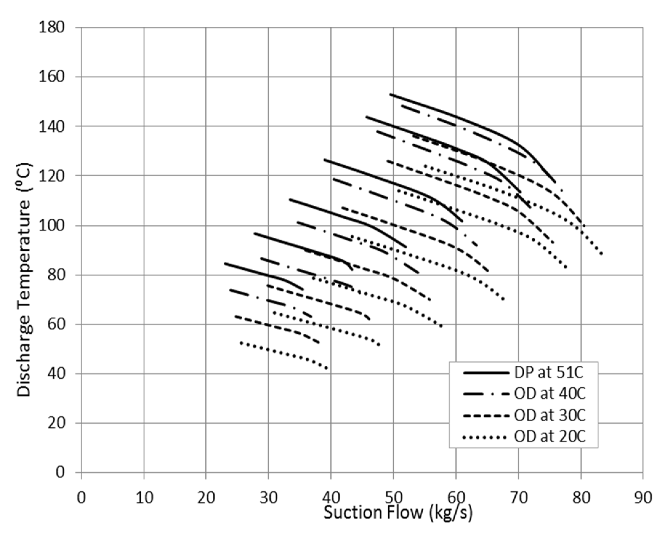
One direct symptom of increasing the suction gas temperature can be detected from the discharge temperature measurement as shown in
Figure 8. Generally, the high discharge temperature is more associated with the increase in the developed head so it could be also a signal for flow surging.
Figure 8.
Effect of gas temperature on the compressor discharge temperature.
Figure 8.
Effect of gas temperature on the compressor discharge temperature.
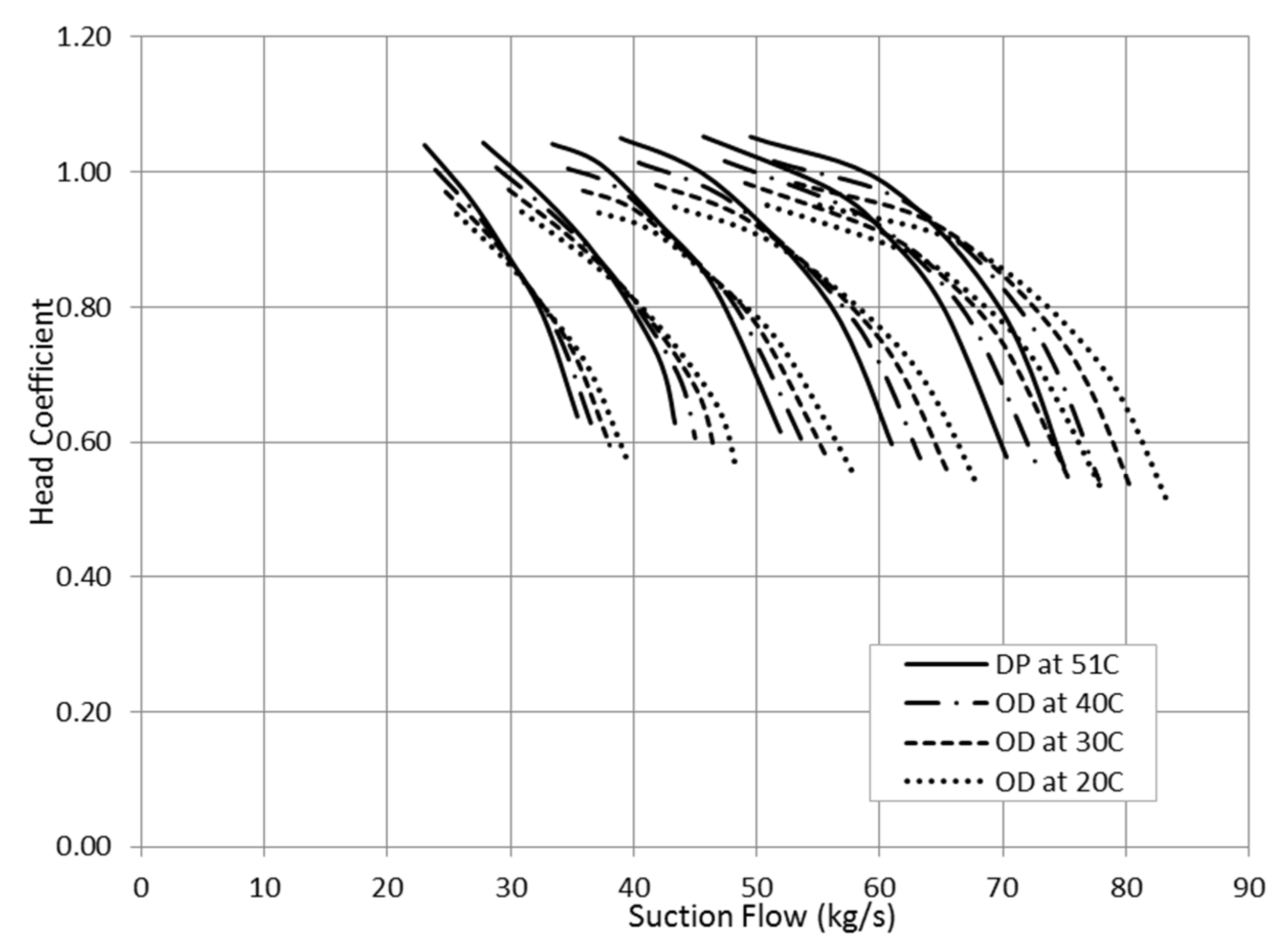
Figure 9 illustrates the variation in head coefficient as a result of suction temperature change. The head at high flow rates is increasing as the temperature goes down while it is taking an opposite trend at low suction flows. This behaviour can be explained by looking back to the parameters that influence the head value. The compressor head is increasing proportionally with the suction temperature and at the same time with the pressure ratio. However, the low inlet temperature pushes the compressor to work with greater pressure ratios. This creates an opposite impact of temperature reduction and the pressure ratio increase on the polytropic head.
Figure 9.
Effect of suction temperature on head coefficient.
Figure 9.
Effect of suction temperature on head coefficient.
From
Figure 7, the influence of low suction temperature on the pressure ratio is getting smaller as the flow shifts towards the surge point. This gives a chance for the low suction temperature to become the dominant factor yielding to lower head. This explains the increase in the head reduction in consequence of low operating temperature as the suction flow decreases.
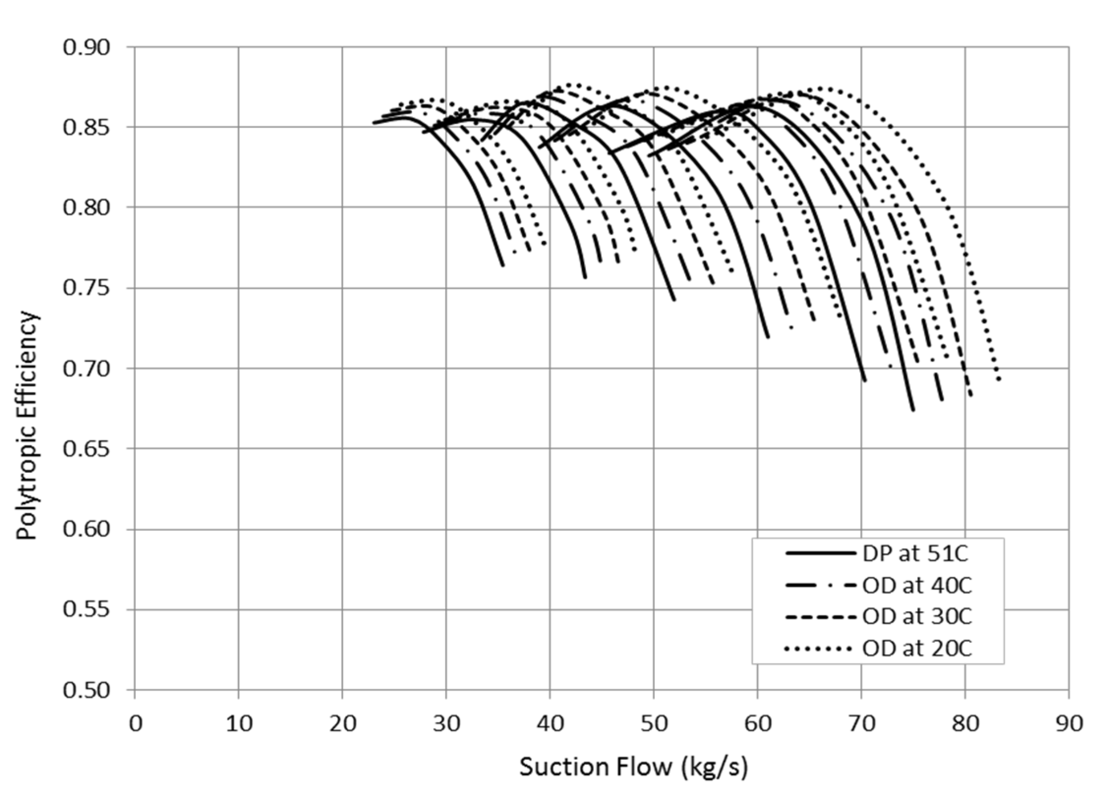
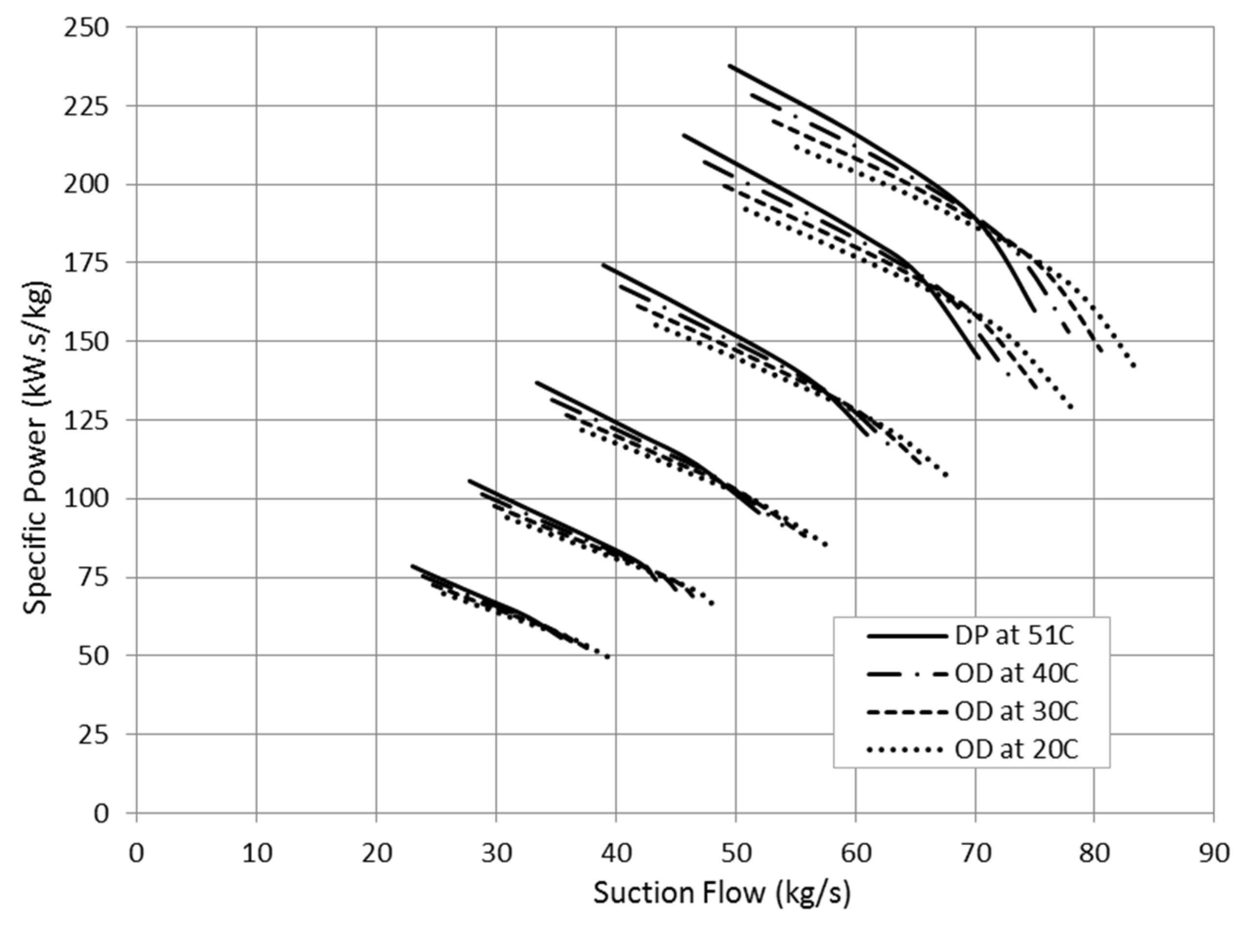
The specific power trend demonstrates an increase in the required shaft power at high suction temperature driven by the head rise in
Figure 10 and the efficiency drop in
Figure 11. In terms of density, the high operating temperature reduces the gas density, leading to lower Reynolds number and higher frictional and heat losses. The power consumption at low inlet temperature was found to be greater at very high flow coefficients and only for narrow flow range due to the increase in the choke flow. Moreover, the power saving at low inlet temperature becomes greater as the suction flow decreases. This finding clearly agrees with the efficiency trend in
Figure 11.
Figure 10.
Effect of gas temperature variation on compressor specific power.
Figure 10.
Effect of gas temperature variation on compressor specific power.
Figure 11.
Effect of gas temperature variation on polytropic head.
Figure 11.
Effect of gas temperature variation on polytropic head.
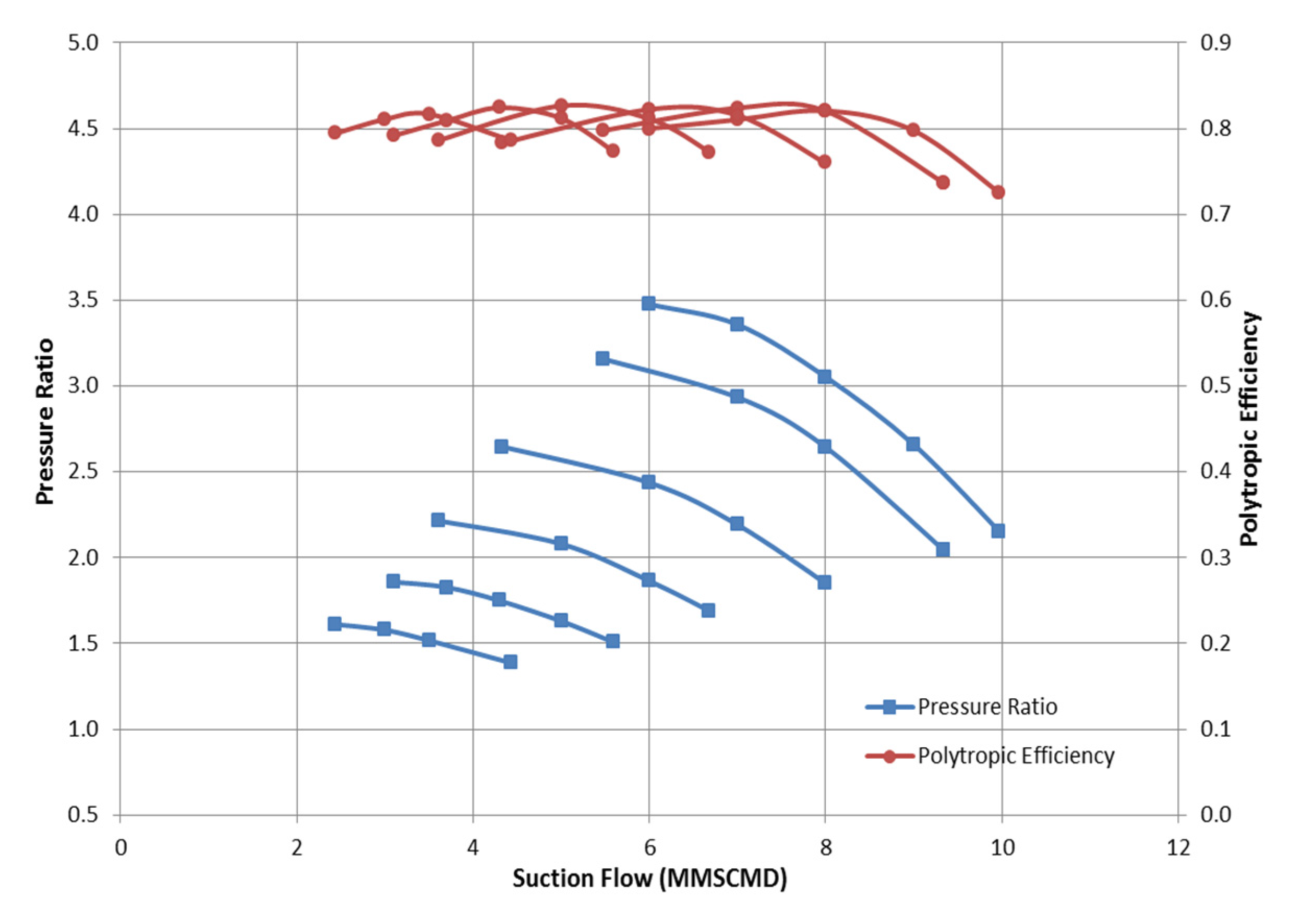
5. Significance of Suction Pressure
A centrifugal compressor is required for depletion gas station to generate a discharge pressure of 112.4 bara at inlet pressure and temperature of 38 bara and 59.8 °C and standard inlet flow of 265,812 m
3/h. The inlet pressure varies from 38 to 60 bara while the discharge compressor is almost constant.
Figure 12 illustrates the actual pressure ratios and polytropic efficiency of this compressor at design conditions. However, the suction pressure is expected to vary from around 30 to 60 bara due to the fluctuation in the exit pressure from the wells or separators or it might be as a result of filter blockage.
Figure 12.
Obtained compressor map based on the measured pressure ratio and efficiency at design conditions.
Figure 12.
Obtained compressor map based on the measured pressure ratio and efficiency at design conditions.
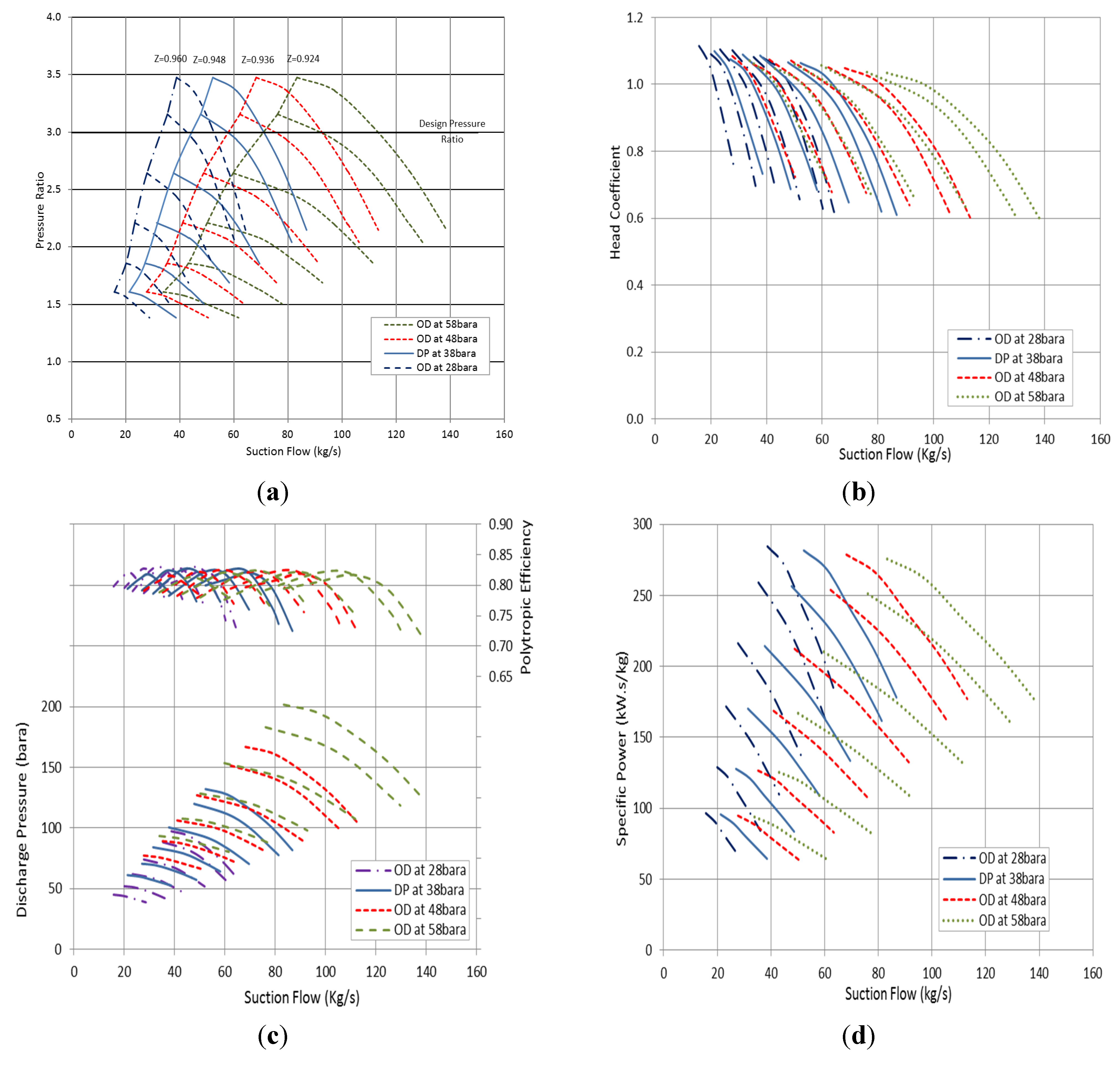
Figure 13a shows the variation in the overall pressure ratio at constant pressure ratio. Unlike the suction temperature, the low inlet pressure causes the operating envelope to shift towards lower flow rates. Additionally, it is clear that the surge margin is also decreasing proportionally with the suction pressure reduction. Furthermore, the stable operating margin is shorted by reducing the suction pressure. It is also interesting to observe that when there is a small change in the suction pressure ranging from +17% to −17%, the suction flow can be maintained to achieve the desired pressure ratio by controlling the rotational speed. However, when the deviation in the inlet pressure goes beyond this range, the pressure ratio cannot be maintained without changing the flow rate.
In terms of compressibility factor, the compressibility factor (
) is increasing as the inlet pressure decreases due to the reduction in the reduced pressure while the reduced temperature is constant. This totally agrees with the compressibility factor charts. The head curve in
Figure 13b is following the pressure ratio trend and shifting towards lower flow as the inlet pressure reduces. However, the higher pressure losses associated with low gas density leads to a slight increase in the required polytropic head in order to achieve almost the same pressure ratio. The specific power curve demonstrates a small increase in the power consumption at low suction pressure. The impact of the suction pressure variation in the polytropic efficiency is illustrated in
Figure 13c.
It was found that operating the compressor at constant pressure ratio yields to lower overall efficiency as the suction pressure goes down. This can be deduced by observing the change in the peak efficiency value in consequence of inlet flow shift. Lowering the suction pressure leads to reduce Reynolds number due to the density decrease. This number is highly influences the induced boundary layer and frictional losses of the flowing gas along its path. The low gas Reynolds number causes higher frictional losses and heat losses through the casing which, in consequence, yield to lower overall efficiency. This conclusion obviously agrees with the specific power curve in
Figure 13d which demonstrates a greater power consumption at low inlet pressure operation.
The compressor is normally designed with an optimum flow coefficient to ensure the high efficiency. However, when there is a small fall in the flow rate as a result of inlet pressure drop, this can be balanced by reducing the rotational speed. Looking to the discharge pressure variations, it is clear that the capacity control is necessary to keep a stable compressor running while the suction pressure is changing. As the suction pressure rises, the discharge pressure increases proportionally but, to keep the running point away from surge, the inlet flow should be raised.
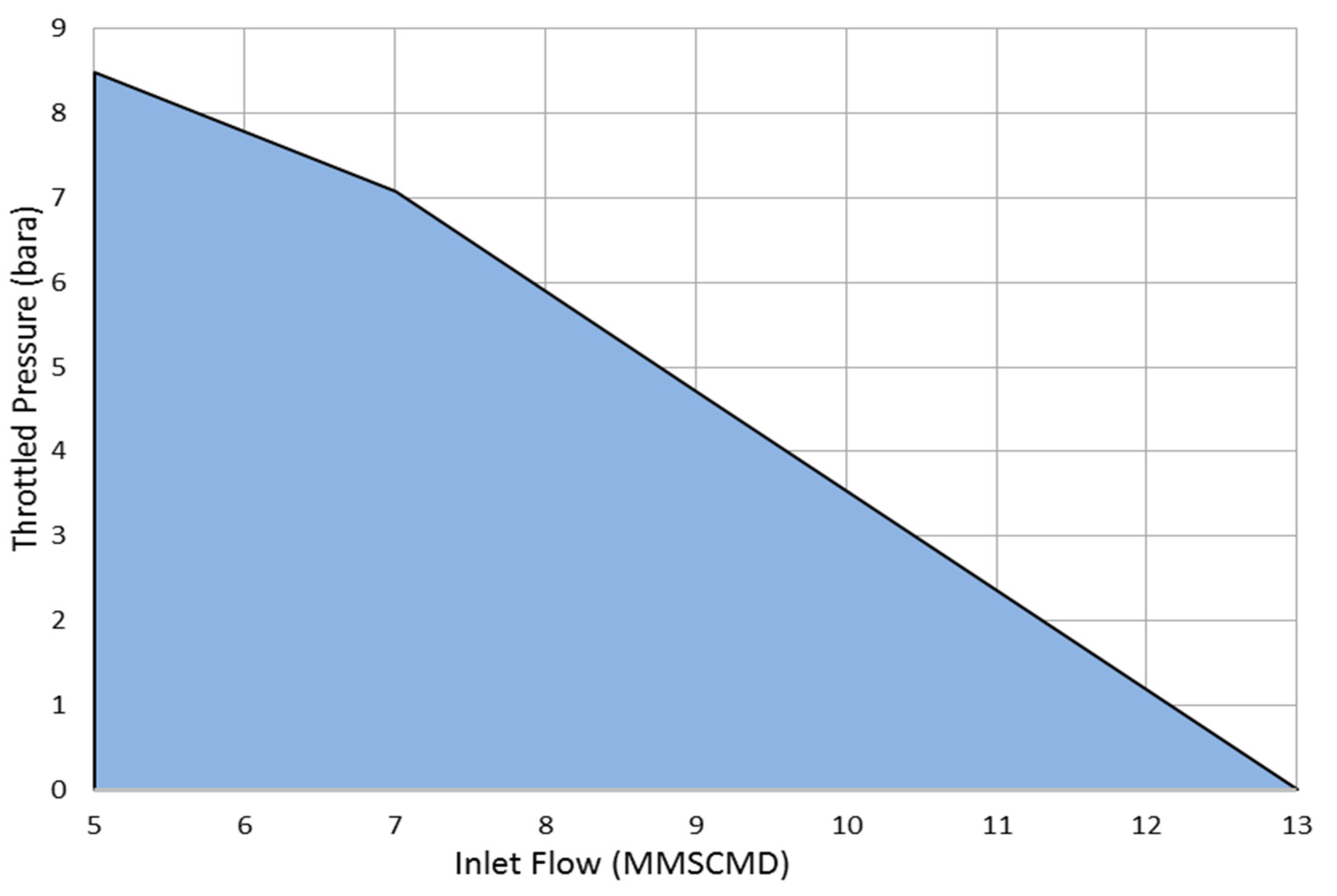
At constant speed line, a fixed discharge pressure can be achieved by altering the inlet pressure. However, to shift the compressor curve to new suction pressure curve, it would be necessary to throttle the suction by a certain amount of pressure which is dissipated in the throttling valve as wasted energy.
Figure 14 demonstrates the amount of suction pressure which has to be throttled using the suction control valve against the inlet flow and assuming a design inlet pressure of 58 bara. This, in consequence, yields to raise the required inlet shaft power comparing with the speed variation control method as the inlet flow goes down which in turn leads to relatively lower efficiency.
To obtain the compressor performance at constant discharge pressure, three main steps were followed:
The compressor map was derived at the beginning, assuming a constant suction pressure. Then, the obtained pressure ratio is used to calculate the corresponding suction pressure, assuming a constant discharge pressure.
The suction gas properties have to be corrected based on the new inlet pressure value. In the next step, the gas properties at compressor suction are recalculated for every suction pressure value including compressibility factor (), compressibility functions (, ), and density ().
For best results, the new pressure ratio values in the first iteration are used again to recalculate the suction pressure, which then used to determine the suction gas properties.
Figure 13.
Effect of suction pressure on compressor performance parameters: (a) Pressure ratio; (b) Head coefficient; (c) Polytropic efficiency; (d) Specific power.
Figure 13.
Effect of suction pressure on compressor performance parameters: (a) Pressure ratio; (b) Head coefficient; (c) Polytropic efficiency; (d) Specific power.
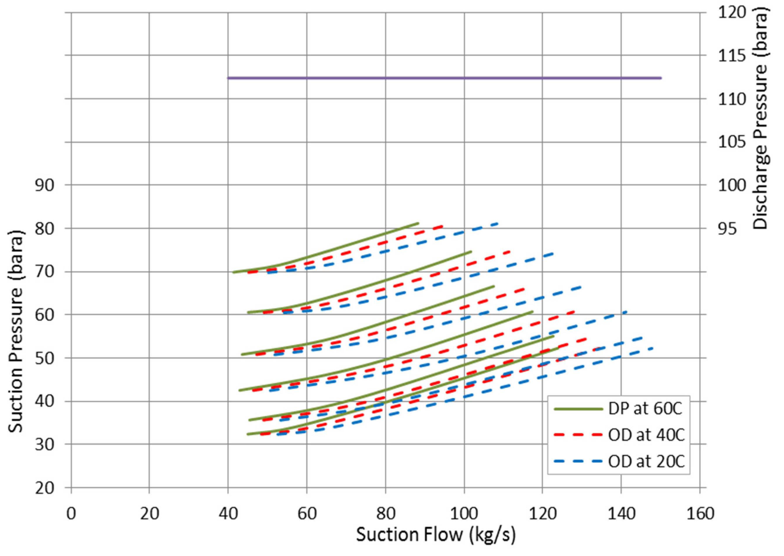
The discharge pressure was considered fixed at the design point value and the corresponding suction pressures are plotted in
Figure 15 at various suction temperatures. This sort of presentation is useful to obtain the equivalent rotational speed and flow rate to achieve the same discharge pressure at different suction pressure and temperature values. To develop the same discharge pressure, the required rotational speed and suction flow are increasing as the inlet pressure decreases in order to keep the running point in the stable region.
Figure 16 illustrates the increase in the compression pressure ratio to accommodate the reduction in suction pressure. At constant suction flow, the compressor is pushed to work with a greater pressure ratio when the inlet temperature goes down due to the reduction in suction pressure. According to polytropic head, the effect of inlet temperature on the constant speed and discharge pressure curve becomes more significant at low flow rates. On the high flow region, the low inlet temperature can introduce a greater increase in the pressure ratio which definitely offsets its direct effect on the polytropic head.
Figure 14.
Predicted throttled pressure with suction throttling controller.
Figure 14.
Predicted throttled pressure with suction throttling controller.
The opposite impact of the inlet temperature and pressure ratio on the compressor head results in, relatively, very close head values at this flow region. However, as the operating point moves to the low flow coefficients region, the rise on the pressure ratio as result of inlet temperature reduction starts to decline which makes its impact on the polytropic head insignificant comparing with the low inlet temperature effect. Consequently, the developed head of high inlet temperature becomes greater at low flow rates.
Figure 15.
Prediction of suction flow and rotational speed at various suction pressures to maintain a constant discharge pressure.
Figure 15.
Prediction of suction flow and rotational speed at various suction pressures to maintain a constant discharge pressure.
Figure 16.
Effect of suction pressure and temperature on compressor pressure ratio at constant discharge pressure.
Figure 16.
Effect of suction pressure and temperature on compressor pressure ratio at constant discharge pressure.
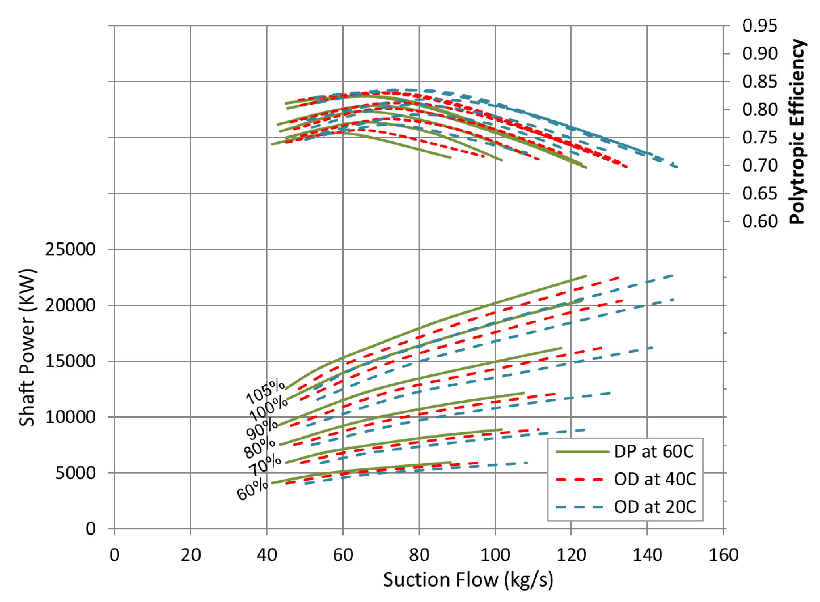
Although that the compressor is working with lower head at high suction pressures, the power curve in
Figure 17 demonstrates an increase in the required power value at high suction pressure region. This is basically due to the fact that the pressure losses are increasing as the deviation of the pressure ratio from the design value increases. As the suction pressure rises beyond 38 bara, the required discharge pressure can be accomplished with relatively smaller pressure ratio than the design point value which in turn yields to dissipate a greater part of the supplied energy. This can be confirmed by looking to the efficiency curve which shows a gradual reduction in the overall compressor efficiency as the suction pressure increases further than the design value.
Figure 17.
Effect of suction pressure and temperature on the compressor efficiency and shaft power.
Figure 17.
Effect of suction pressure and temperature on the compressor efficiency and shaft power.


