
A New Adsorbent Composite Material Based on Metal Fiber Technology and Its Application in Adsorption Heat Exchangers

 ,
,
Abstract
:
1. Introduction
2. Preparation of Composite Material
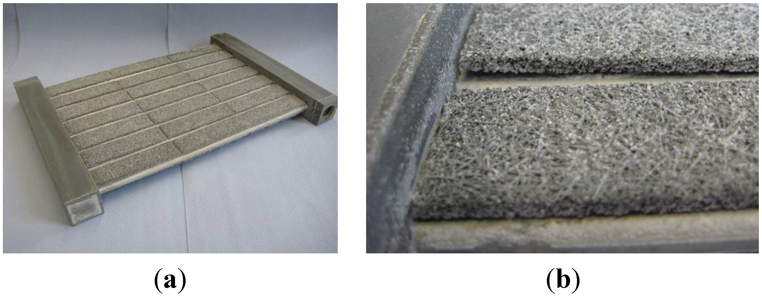
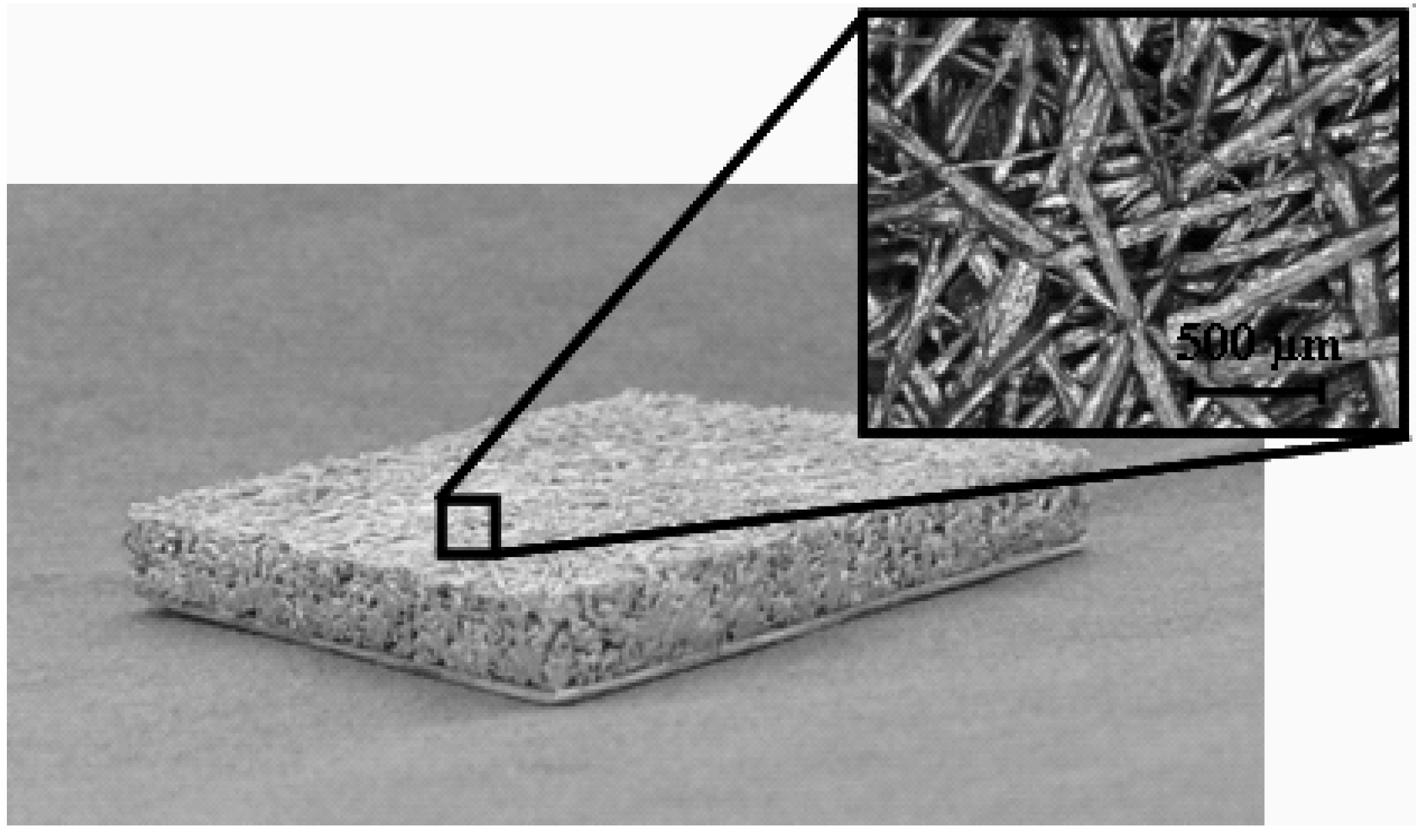
2.1. Aluminum Fiber Structures
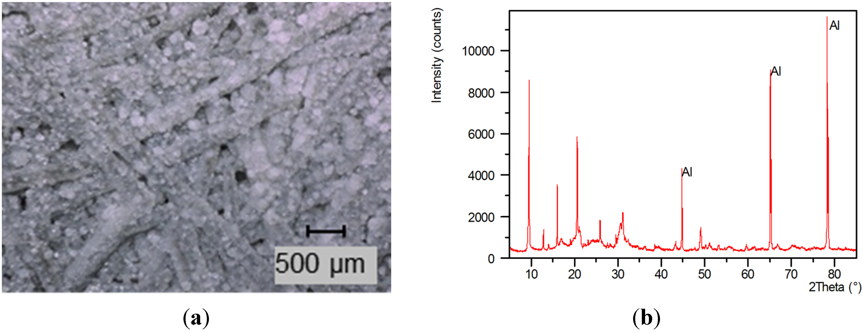
2.2. In Situ Crystallization of SAPO-34 on Aluminum Fiber Structures

| Material propery | Unit | Value |
|---|---|---|
| Heat Conductivity | W/m K | 9 |
| Mean macropore diameter | m | 150 × 10−6 |
| Macro porosity fibers | % | 75 |
| Macro porosity composite | % | 29 |
| Tortuosity | - | 2–3 |
| Permeability | m2 | 1 × 10⁻¹⁰ |

2.3. Material Properties
3. Adsorption Characteristics of Small Sample

| Parameter | Unit | Small Sample | Prototype |
|---|---|---|---|
| Volume | |||
| Total | m3 | 0.0039 × 10⁻³ | 3 × 10⁻³ a |
| Profiles/support | m3 | 0.0004 × 10⁻³ | 0.495 × 10⁻³ |
| Fiber | m3 | 0.0035 × 10⁻³ | 0.315 × 10⁻³ |
| Mass | |||
| Mass adsorbent | kg | 2.2 × 10⁻³ | 0.240 |
| Total mass b | kg | 6.8 × 10⁻³ | 1.350 |
| Specific values | |||
| Mass adsorbent per total mass | kg/kg | 0.32 | 0.18 |
| Mass adsorbent per volume composite | kg/m3 | 620 | 760 |
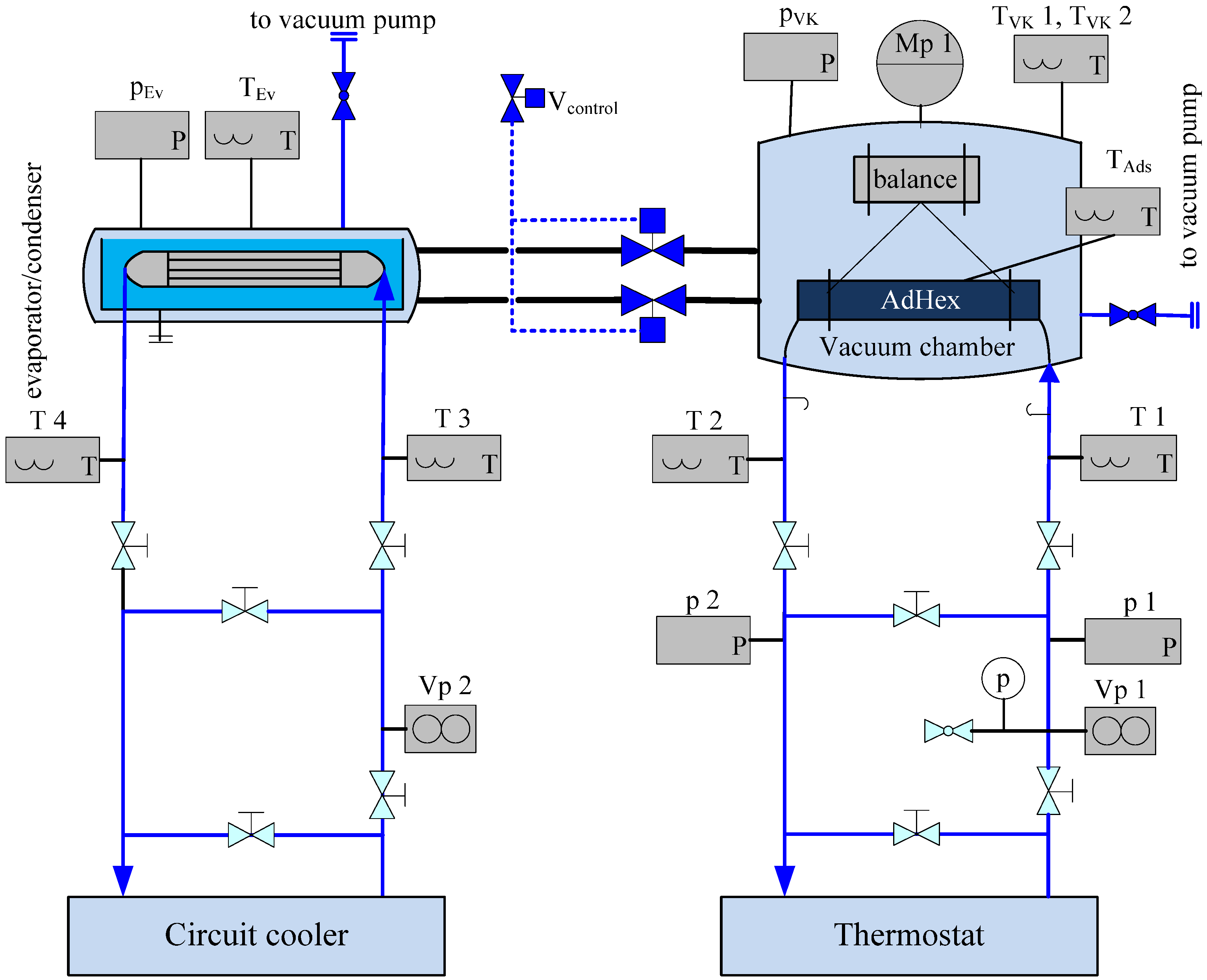
4. Lab-Scale Adsorbent Heat Exchanger (AdHEX)
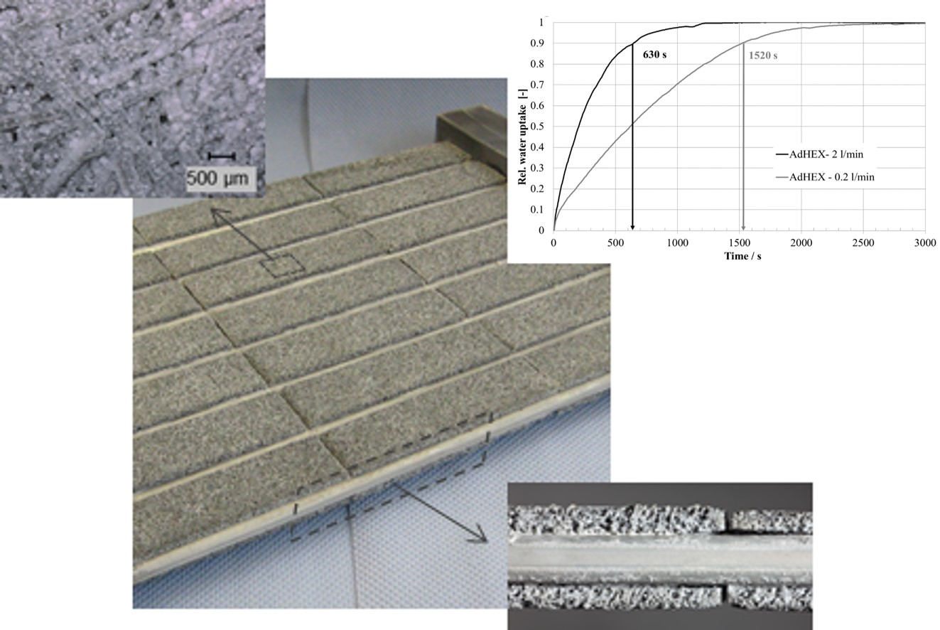
4.1. Construction and Coating

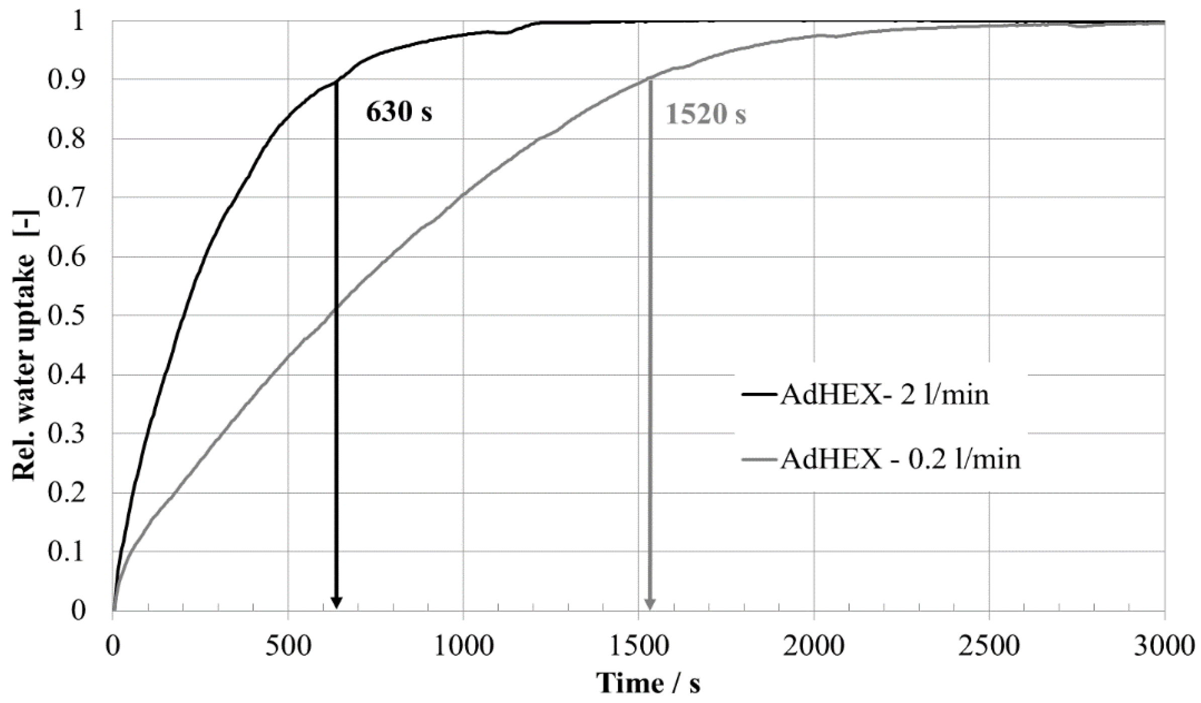
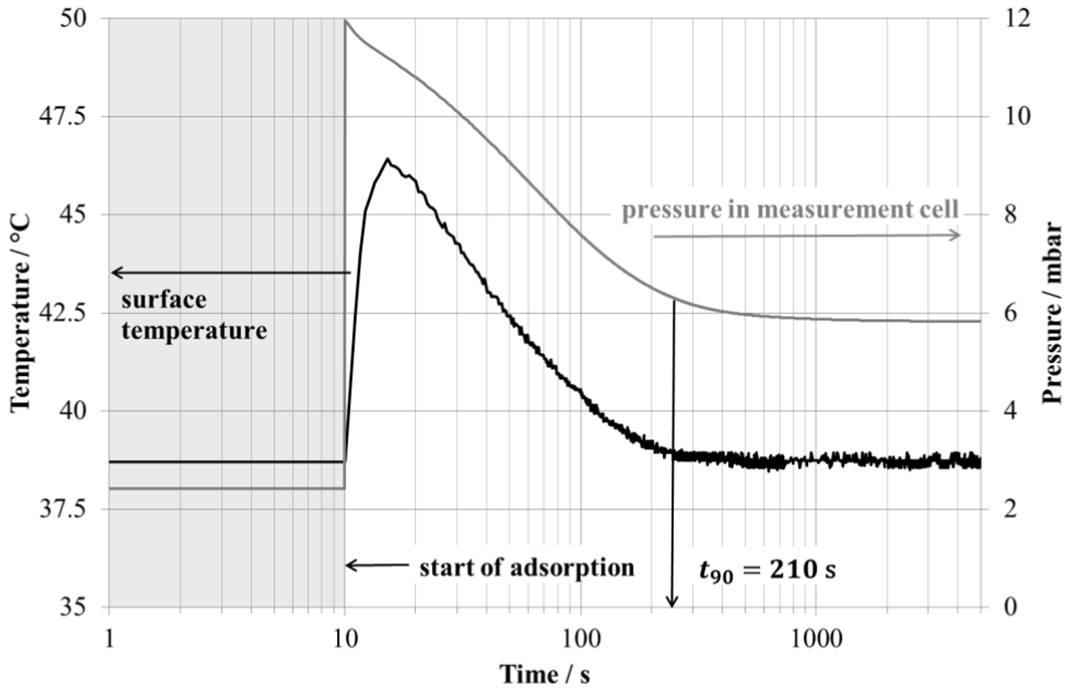
4.2. Characterization
| Parameter | Value | Parameter | Value |
|---|---|---|---|
| a | 0.33657 cm3/g | g | −1.26124 × 10⁻⁸ (cm3·g2)/J3 |
| b | −0.00786 g/J | h | 3.86925 × 10⁻¹¹ g4/J4 |
| c | −0.00270 cm3/J | i | 9.22605 × 10⁻¹² (cm3·g3)/J4 |
| d | 2.53508 × 10⁻⁵ g2/J2 | j | −8.10788 × 10⁻¹⁵ g5/J5 |
| e | 8.39344 × 10⁻⁶ (cm3·g)/J2 | k | −2.48858 × 10⁻¹⁵ (cm3·g4)/J5 |
| f | −4.35518 × 10⁻⁸ g3/J3 |


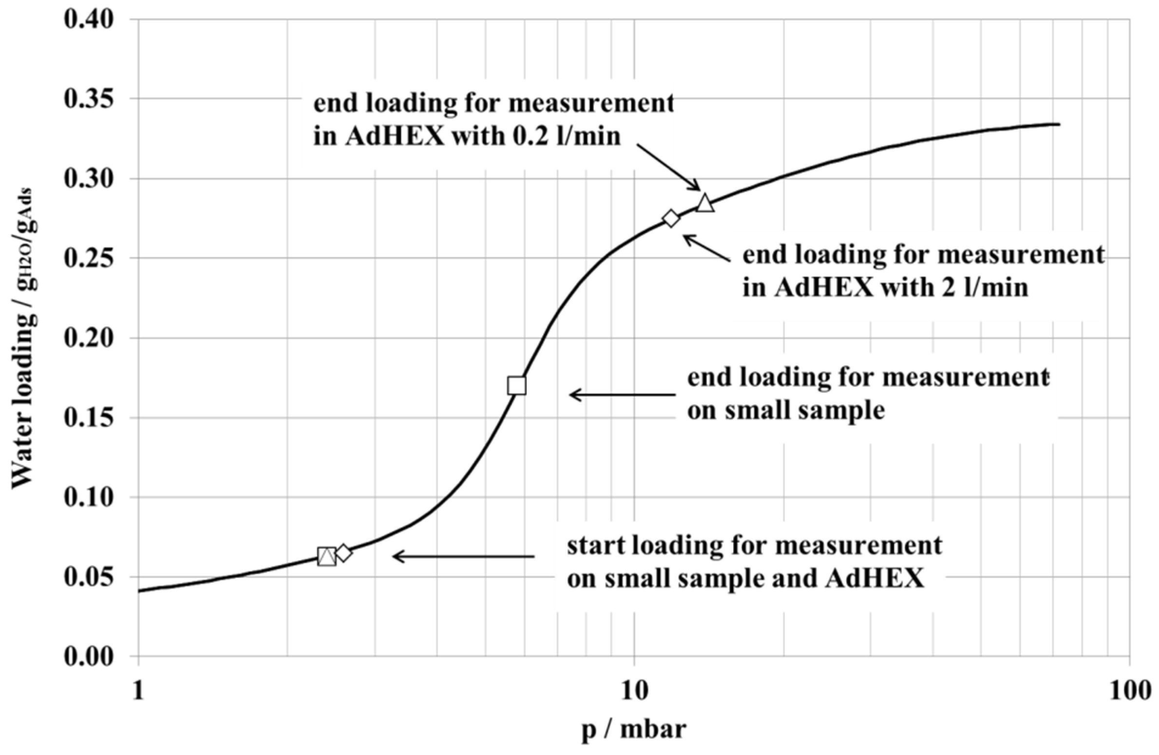
| Parameter | Small Sample | AdHEX | |
|---|---|---|---|
| Volume flow of heat transfer fluid | 0.2 L/min | 2 L/min | |
| Desorption temperature | 95 °C | 92 °C | 95 °C |
| Adsorption temperature | 38.7 °C | 39.2 °C | 39.8 °C |
| Starting pressure | 2.4 mbar | 2.4 mbar | 2.6 mbar |
| End pressure | 5.8 mbar | 11.9 mbar | 11.9 mbar |
| Pressure Jump | 2.4–12.0 mbar | 2.4–12.1 mbar | 2.6–11.9 mbar |
| Condenser temperature/pressure | 30 °C/42 mbar | 24 °C/30 mbar | 21 °C/25 mbar |
| Start loading (calculated) | 0.06 g/g | 0.06 g/g | 0.06 g/g |
| End loading (calculated) | 0.17 g/g | 0.28 g/g | 0.27 g/g |
| Rel. water uptake (calculated) | 0.11 g/g | 0.22 g/g | 0.21 g/g |
| Abs. water uptake (calculated) | 0.22 g | 52.3 g | 51.1 g |
| Rel. water uptake (measured) | 0.09 g/g | 0.23 g/g | 0.22 g/g |
| Abs. water uptake (measured) | 0.18 g ± 0.01 g | 55 g ± 2 g | 53 g ± 2 g |
| Time 90% uptake t90 | 210 s | 1520 s | 630 s |
| Rise-up time t80-t15 | 118 s | 1114 s | 407 s |
| Sorption speed Vs | 920 × 10−6 1/s | 187 × 10−6 1/s | 547 × 10−6 1/s |
| Water uptake at t90 | 0.16 g | 49.9 g | 47.4 g |
| Cooling power (t90) | 2 W | 80 W | 184 W |
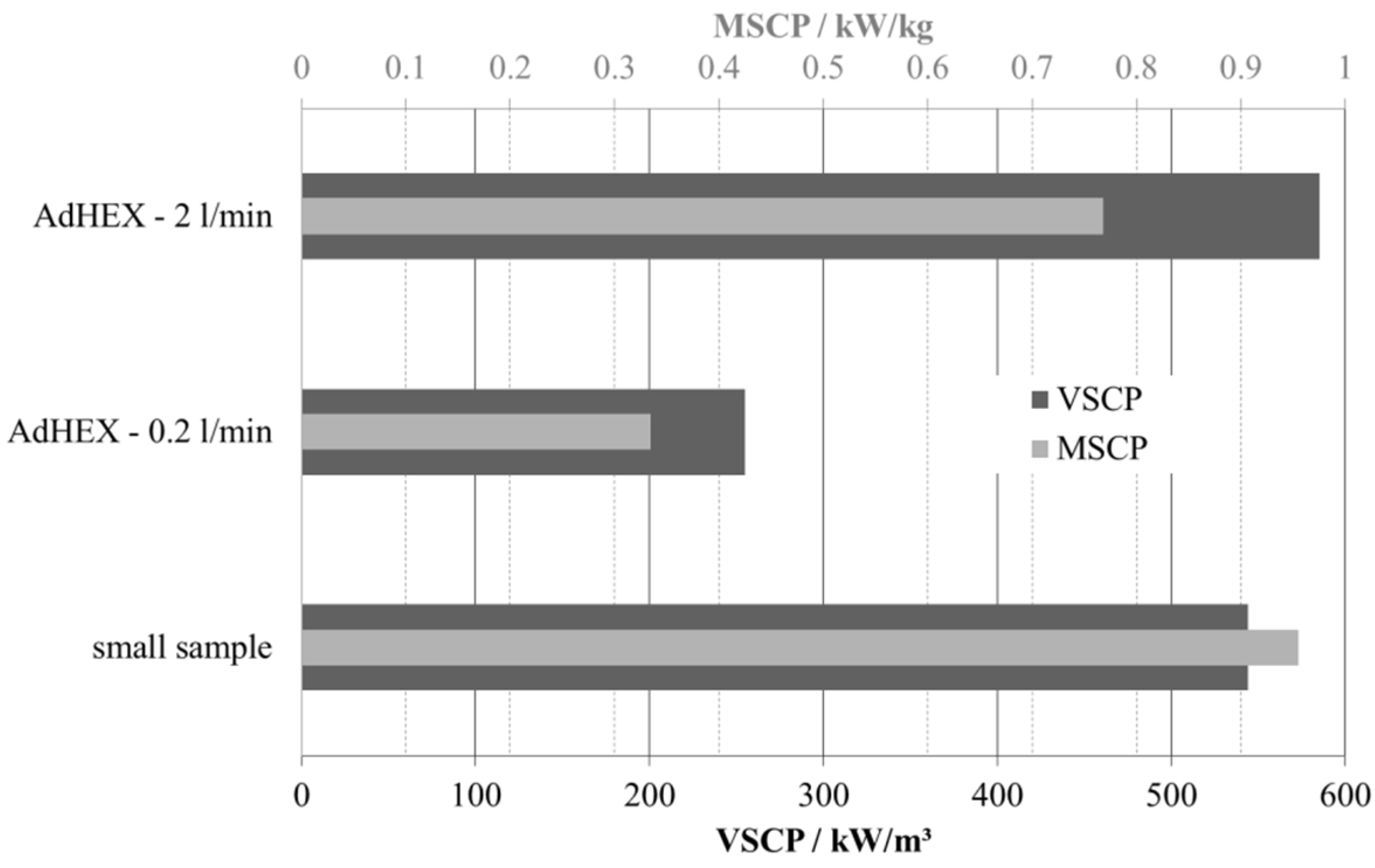
| Volume-specific cooling power (VSCP) | |||
| per volume composite | 545 kW/m3 | 255 kW/m3 | 585 kW/m3 |
| per volume composite + HEX | 273 kW/m3 (1) | 98 kW/m3 | 226 kW/m3 |
| per total volume AdHEX | 55 kW/m3 (2) | 26 kW/m3 | 59 kW/m3 |
| Mass-specific cooling power (MSCP) | |||
| per mass adsorbent | 0.96 kW/kg | 0.33 kW/kg | 0.77 kW/kg |
5. Conclusions
Acknowledgments
Author Contributions
Conflicts of Interest
Nomenclature
| A | J/g | Adsorption potential |
| Re | - | Reynolds number |
| t50 | s | Time to reach 50% of final loading |
| t80-t15 | s | Rise-up time (time span between 15% and 80% of final loading) |
| t90 | s | Time to reach 90% of final loading |
| Vs | 1/s | Sorption speed (loading (t50)/t50) |
| W | cm3/g | Adsorbed volume |
| m2 | Permeability | |
| - | Tortuosity | |
| % | Macro porosity of composite material |
Abbreviations
| AdHEX | Adsorption heat exchanger |
| COP | Coefficient of performance |
| ICP-OES | Inductively Coupled Plasma-Optical Emission Spectroscopy |
| PST | Partial support transformation |
| MSCP | Mass-specific cooling power |
| SEM | Scanning electron microscopy |
| VSCP | Volume specific cooling power |
| XRD | X-ray diffraction |
References
- Rezk, A.; Al-Dadah, R.K.; Mahmoud, S.; Elsayed, A. Effects of contact resistance and metal additives in finned-tube adsorbent beds on the performance of silica gel/water adsorption chiller. Appl. Therm. Eng. 2013, 53, 278–284. [Google Scholar]
- Wienen, J.; Neubert, M.; Lang, R.; Tiemeier, H. Results from field trial with gas heat pump Zeotherm by Vaillant. In Thermally Driven Heat Pumps for Heating and Cooling; Kühn, A., Ed.; Universitätsverlag der TU Berlin: Berlin, Geramny, 2013. [Google Scholar]
- Núñez, T.; Mittelbach, W.; Henning, H.-M. Development of an adsorption chiller and heat pump for domestic heating and air-conditioning applications. Appl. Therm. Eng. 2007, 27, 2205–2212. [Google Scholar]
- Schicktanz, M.; Núñez, T. Modelling of an adsorption chiller for dynamic system simulation. Int. J. Refrig. 2009, 32, 588–595. [Google Scholar]
- Wang, L.; Zhu, D.; Tan, Y. Heat transfer enhancement of the adsorber of an adsorption heat pump. Adsorption 1999, 5, 279–286. [Google Scholar]
- Zhang, L.Z. Design and testing of an automobile waste heat adsorption cooling system. Appl. Therm. Eng. 2000, 20, 103–114. [Google Scholar]
- Demir, H.; Mobedi, M.; Ülkü, S. The use of metal piece additives to enhance heat transfer rate through an unconsolidated adsorbent bed. Int. J. Refrig. 2010, 33, 714–720. [Google Scholar]
- Riffel, D.B.; Wittstadt, U.; Schmidt, F.P.; Nunez, T.; Belo, F.A.; Leite, A.P.F.; Ziegler, F. Transient modeling of an adsorber using finned-tube heat exchanger. Int. J. Heat Mass Transf. 2010, 53, 1473–1482. [Google Scholar]
- Chang, K.S.; Chen, M.T.; Chung, T.W. Effects of the thickness and particle size of silica gel on the heat and mass transfer performance of a silica gel-coated bed for air-conditioning adsorption systems. Appl. Therm. Eng. 2005, 25, 2330–2340. [Google Scholar]
- Chang, W.S.; Wang, C.C.; Shieh, C.C. Experimental study of a solid adsorption cooling system using flat-tube heat exchangers as adsorption bed. Appl. Therm. Eng. 2007, 27, 2195–2199. [Google Scholar]
- Aristov, Y.I. Experimental and numerical study of adsorptive chiller dynamics: Loose grains configuration. Appl. Therm. Eng. 2013, 61, 841–847. [Google Scholar]
- Grisel, R.J.H.; Smeding, S.F.; de Boer, R. Waste heat driven silica gel/water adsorption cooling in trigeneration. Appl. Therm. Eng. 2010, 30, 1039–1046. [Google Scholar]
- Freni, A.; Sapienza, A.; Glaznev, I.S.; Aristov, Y.I.; Restuccia, G. Experimental testing of a lab-scale adsorption chiller using a novel selective water sorbent “silica modified by calcium nitrate”. Int. J. Refrig. 2012, 35, 518–524. [Google Scholar] [CrossRef]
- Santamaria, S.; Sapienza, A.; Frazzica, A.; Freni, A.; Girnik, I.S.; Aristov, Y.I. Water adsorption dynamics on representative pieces of real adsorbers for adsorptive chillers. Appl. Energy 2014, 134, 11–19. [Google Scholar] [CrossRef]
- Sharafian, A.; Bahrami, M. Assessment of adsorber bed designs in waste-heat driven adsorption cooling systems for vehicle air conditioning and refrigeration. Renew. Sustain. Energy Rev. 2014, 30, 440–451. [Google Scholar] [CrossRef]
- Jaeschke, S.; Wolf, M. Schichtverbund und seine Herstellung. German Patent DE102005038044, 10 August 2008. [Google Scholar]
- Freni, A.; Russo, F.; Vasta, S.; Tokarev, M.; Aristov, Y.I.; Restuccia, G. An advanced solid sorption chiller using SWS-1L. Appl. Therm. Eng. 2007, 27, 2200–2204. [Google Scholar] [CrossRef]
- Munz, G.M.; Bongs, C.; Morgenstern, A.; Lehmann, S.; Kummer, H.; Henning, H.M.; Henninger, S.K. First results of a coated heat exchanger for the use in dehumidification and cooling processes. Appl. Therm. Eng. 2013, 61, 878–883. [Google Scholar] [CrossRef]
- Dawoud, B. Water vapor adsorption kinetics on small and full scale zeolite coated adsorbers: A comparison. Appl. Therm. Eng. 2013, 50, 1645–1651. [Google Scholar] [CrossRef]
- Tatlıer, M.; Erdem-Şenatalar, A. The effects of thermal gradients in a solar adsorption heat pump utilizing the zeolite-water pair. Appl. Therm. Eng. 1999, 19, 1157–1172. [Google Scholar] [CrossRef]
- Bonaccorsi, L.; Calabrese, L.; Proverbio, E. Low temperature single-step synthesis of zeolite y coatings on aluminium substrates. Microporous Mesoporous Mater. 2011, 144, 40–45. [Google Scholar] [CrossRef]
- Freni, A.; Frazzica, A.; Dawoud, B.; Chmielewski, S.; Calabrese, L.; Bonaccorsi, L. Adsorbent coatings for heat pumping applications: Verification of hydrothermal and mechanical stabilites. Innov. Mater. Process. Energy Syst. 2010, 50, 1658–1663. [Google Scholar]
- Bauer, J.; Herrmann, R.; Mittelbach, W.; Schwieger, W. Zeolite/aluminum composite adsorbents for application in adsorption heat pumps. Int. J. Energy Res. 2009, 33, 1233–1249. [Google Scholar] [CrossRef]
- Schwieger, W.; Thangaraj, S.; Scheffler, F.; Herrmann, R.; Reddy, M.; Mittelbach, W.; Bauer, J.; Schmidt, F.; Hennig, H.-M. Method for Production of a Substrate coated with a Zeolite Layer. US 8,053,032 B2, 29 October 2004. [Google Scholar]
- Freni, A.; Bonaccorsi, L.; Proverbio, E.; Maggio, G.; Restuccia, G. Zeolite synthesised on copper foam for adsorption chillers: A mathematical model. Microporous Mesoporous Mater. 2009, 120, 402–409. [Google Scholar] [CrossRef]
- Schnabel, L.; Tatlier, M.; Schmidt, F.; Erdem-Şenatalar, A. Adsorption kinetics of zeolite coatings directly crystallized on metal supports for heat pump applications (adsorption kinetics of zeolite coatings). Appl. Therm. Eng. 2010, 30, 1409–1416. [Google Scholar] [CrossRef]
- Bonaccorsi, L.; Bruzzaniti, P.; Calabrese, L.; Freni, A.; Proverbio, E.; Restuccia, G. Synthesis of sapo-34 on graphite foams for adsorber heat exchangers. Appl. Therm. Eng. 2013, 61, 848–852. [Google Scholar] [CrossRef]
- Aristov, Y.I. Adsorption dynamics in adsorptive heat transformers: Review of new trends. Heat Transf. Eng. 2014, 35, 1014–1027. [Google Scholar] [CrossRef]
- Lang, R.; Westerfeld, T.; Gerlich, A.; Knoche, K.F. Enhancement of the heat and mass transfer in compact zeolite layers. Adsorption 1996, 2, 121–132. [Google Scholar] [CrossRef]
- Guilleminot, J.-J.; Choisier, A.; Chalfen, J.B.; Nicolas, S.; Reymoney, J.L. Heat transfer intensification in fixed bed adsorbers. Heat Recover. Syst. 1993, 13, 297–300. [Google Scholar] [CrossRef]
- Atakan, A.; Fueldner, G.; Munz, G.; Henninger, S.; Tatlier, M. Adsorption kinetics and isotherms of zeolite coatings directly crystallized on fibrous plates for heat pump applications. Appl. Therm. Eng. 2013, 58, 273–280. [Google Scholar] [CrossRef]
- Tatlier, M.; Munz, G.; Fueldner, G.; Henninger, S.K. Effect of zeolite a coating thickness on adsorption kinetics for heat pump applications. Microporous Mesoporous Mater. 2014, 193, 115–121. [Google Scholar] [CrossRef]
- Freni, A.; Dawoud, B.; Bonaccorsi, L.; Chmielewski, S.; Frazzica, A.; Calabrese, L.; Restuccia, G. Characterization of Zeolite-based Coatings for Adsorption Heat Pumps; Springer International Publishing: Cham, Switzerland, 2015. [Google Scholar]
- Henninger, S.K.; Schmidt, F.P.; Henning, H.-M. Water adsorption characteristics of novel materials for heat transformation applications. Appl. Therm. Eng. 2010, 30, 1692–1702. [Google Scholar] [CrossRef]
- Henninger, S.K.; Jeremias, F.; Kummer, H.; Schossig, P.; Henning, H.-M. Novel sorption materials for solar heating and cooling. Energy Proced. 2012, 30, 279–288. [Google Scholar] [CrossRef]
- Okamoto, K.; Teduka, M.; Nakano, T.; Kubokawa, S.; Kakiuchi, H. The development of AQSOA water vapor adsorbent and AQSOA coated heat exchanger. In Proceedings of the International Symposium on Innovative Materialsfor Processes in Energy Systems (IMPRESS 2010), Singapore, 29 November–1 December 2010; pp. 27–32.
- Jänchen, J.; Ackermann, D.; Weiler, E.; Stach, H.; Brösicke, W. Calorimetric investigation on zeolites, AlPO4’s and CaCl2 impregnated attapulgite for thermochemical storage of heat. Thermochim. Acta 2005, 434, 37–41. [Google Scholar] [CrossRef]
- Lehnert, F.; Lotze, G.; Stephani, G. Herstellung, eigenschaften und anwendung metallischer kurzfasern. Materialwiss. Werkstofftech. 1991, 22, 355–358. [Google Scholar] [CrossRef]
- Andersen, O.; Meinert, J.; Studnitzky, T.; Stephani, G.; Kieback, B. Highly heat conductive open-porous aluminium fibre based parts for advanced heat transfer applications. Materialwiss. Werkstofftech. 2012, 43, 328–333. [Google Scholar] [CrossRef]
- Andersen, O.; Studnitzky, T.; Kostmann, C. Bauteil Sowie Seine Verwendung. German Patent DE102007042494, 3 September 2007. [Google Scholar]
- Andersen, O.; Stephani, G.; Meyer-Olbersleben, F.; Neumann, P. Properties of highly porous metal fibre components for high temperature applications. In Proceedings of the International Conference on Powder Metallurgy & Particulate Materials, Princeton, NJ, USA, 31 May–4 June 1998; Volume 3, pp. 87–97.
- Veyhl, C.; Fiedler, T.; Andersen, O.; Meinert, J.; Bernthaler, T.; Belova, I.V.; Murch, G.E. On the thermal conductivity of sintered metallic fibre structures. Int. J. Heat Mass Transf. 2012, 55, 2440–2448. [Google Scholar] [CrossRef]
- Frazzica, A.; Füldner, G.; Sapienza, A.; Freni, A.; Schnabel, L. Experimental and theoretical analysis of the kinetic performance of an adsorbent coating composition for use in adsorption chillers and heat pumps. Appl. Therm. Eng. 2014, 73, 1020–1029. [Google Scholar] [CrossRef]
- Füldner, G. Stofftransport und Adsorptionskinetik in porösen Adsorbenskompositen für Wärmetransformationsanwendungen; Albert-Ludwigs-Universität Freiburg: Freiburg im Breisgau, Germany, 2015. (In German) [Google Scholar]
- Kast, W. Diffusive mass transfer with superimposed frictional flow. Int. J. Heat Mass Transf. 2001, 44, 4717–4724. [Google Scholar] [CrossRef]
- Schnabel, L. Experimentelle und Numerische Untersuchung der Adsorptionskinetik von Wasser an Adsorbens-Metallverbundstrukturen. Ph.D. Thesis, Technische Universität Berlin, Berlin, Germany, 2009. [Google Scholar]
- Wittstadt, U.; Jahnke, A.; Schnabel, L.; Sosnowski, M.; Schmidt, F.P.; Ziegler, F. Test facility for small-scale adsorbers. In Proceedings of the International Sorption Heat Pump Conference 2008, Seoul, Korea, 23–26 September 2008.
- Núñez, T. Charakterisierung und Bewertung von Adsorbentien für Wärmetransformationsanwendungen; Albert-Ludwigs-Universität Freiburg: Freiburg im Breisgau, Germany, 2001. (In German) [Google Scholar]
© 2015 by the authors; licensee MDPI, Basel, Switzerland. This article is an open access article distributed under the terms and conditions of the Creative Commons Attribution license (http://creativecommons.org/licenses/by/4.0/).
Share and Cite
Wittstadt, U.; Füldner, G.; Andersen, O.; Herrmann, R.; Schmidt, F. A New Adsorbent Composite Material Based on Metal Fiber Technology and Its Application in Adsorption Heat Exchangers. Energies 2015, 8, 8431-8446. https://doi.org/10.3390/en8088431
Wittstadt U, Füldner G, Andersen O, Herrmann R, Schmidt F. A New Adsorbent Composite Material Based on Metal Fiber Technology and Its Application in Adsorption Heat Exchangers. Energies. 2015; 8(8):8431-8446. https://doi.org/10.3390/en8088431
Chicago/Turabian StyleWittstadt, Ursula, Gerrit Füldner, Olaf Andersen, Ralph Herrmann, and Ferdinand Schmidt. 2015. "A New Adsorbent Composite Material Based on Metal Fiber Technology and Its Application in Adsorption Heat Exchangers" Energies 8, no. 8: 8431-8446. https://doi.org/10.3390/en8088431
APA StyleWittstadt, U., Füldner, G., Andersen, O., Herrmann, R., & Schmidt, F. (2015). A New Adsorbent Composite Material Based on Metal Fiber Technology and Its Application in Adsorption Heat Exchangers. Energies, 8(8), 8431-8446. https://doi.org/10.3390/en8088431