1. Introduction
The seriousness of environmental pollution and fossil energy shortages has created an increased interest in the development and utilization of Distributed generation (DG) and electric vehicles (EVs). The large-scale application of EVs alleviates in part the energy shortage [
1], and vehicle-to-grid (V2G) technology allows EVs to provide electricity to the grid at an appropriate time. In addition, vehicle-to-building (V2B) technology can export electrical power from a vehicle battery into a building connected to the distribution system to support load needs [
2,
3]. The intermittent DG, including photovoltaic and wind power, may not provide power on cloudy, windless days and at night. Battery storage (BS) can provide previously stored power for the load in that situation [
4]. Microgrids integrate DG, BS, loads and EVs as one unit to operate in grid-connected mode or island mode, according to the fault state of the distribution network [
5]. With microgrids accessing the grid, the traditional distribution networks with single supplies and radial structure have evolved into new distribution networks with multiple sources and two-way power flow. These changes increase the power flow uncertainty, so the reliability assessment theory and method will inevitably improve. Some research topics have addressed the problems of reliability assessment of new distribution networks. Most present studies mainly focus on microgrids with only DG. The probabilistic model is used to simulate the output power of photovoltaic and wind power [
6,
7], which cover the uncertainty and randomness of intermittent DG, but these two papers do not develop a battery model and ignore the possible influence of batteries. An integrated Markov model that incorporates the DG adequacy transition rate, DG mechanical failure, and starting and switching probability is utilized to give accurate results for the DG reliability assessment in [
8], but the method is only applicable to a distribution network with intermittent DG. The battery changes the real-time power supply relationship between DG and load, so the calculation method for loss of load probability (LOLP) proposed in that paper cannot be implemented for a distribution network with BS. Reference [
9] presents an equivalent conventional generator model for the Point of Common Coupling (PCC) and uses a two-step Monte Carlo simulation method to assess the reliability of distribution systems with microgrids. The equivalent conventional generator model is used to simplify the microgrid evaluation process, but the reliability assessment in microgrids is imperfect because the model does not consider the influence of EVs’ charge demands and discharge capacity on the daily load. The reliability evaluation also can be achieved through a novel evaluation algorithm, which is based on the identification of circuit minimal tie sets using the concept of Petri nets [
10]. This can reduce the number of states and transition matrix size without affecting computation accuracy, but a drawback that is also ignored is that it does not consider new elements in the discussed network, such as BS and EVs. A probabilistic technique is applied to evaluate the distribution system reliability utilizing segmentation concept and a novel constrained Grey predictor technique for wind speed profile estimation [
11]. This can provide a more accurate model to simulate the output of wind power generation and reduce the deviation of reliability evaluation. Like [
6,
7,
8], the model only takes DG into consideration and it has no storage options.
BS stores redundant power at low load and contributes power back to the grid at peak load times. As an important energy buffer link, the BS affects the real-time supply relationship between plants and loads, which adds a new concern for reliability evaluation [
12], whereas the above references have never considered this aspect. The large-scale charging demands of EVs will have an influence on grid load [
13], while vehicle-to-grid (V2G) technology can take on the tasks of peak load shifting [
14]. EVs increase the complexity of power consumption, which exceeds the capability of conventional reliability evaluation models [
8,
9,
10,
11], so distribution systems need to build new reliability evaluation models covering the effects of EVs. Due to the EVs and BS, the energy that flows among DG, EVs, BS and loads has more uncertainty in amount and direction, so a new integrated model should be built to describe the complex energy interactions in microgrids.
The charging load of EVs has randomness in time and space, and has an influence on daily load curves [
15]. There are currently two basic modeling methods for charging demand: (1) under the hypothesis that the driving behavior data are independent of each other, the Monte Carlo simulation method is used to establish a power-charging demand model [
16]; the method does not consider different charging modes, but the charging model has more influence on charging load; (2) according to Queuing Theory, a charging power expression of a charging station is built to achieve the random probability distribution model for charging demand [
17]. The method applies only to calculating charging station loads, and it cannot simulate the charging load of EVs. Like [
16], the model also does not take discharging capacity into consideration. The research on the charging demand and discharging capacity of EVs can describe the complete load curve for distribution networks and improve the accuracy of reliability evaluations. The system should develop reasonable models considering different EV classifications and charging modes to simulate the charging demand and discharging capacity of EVs. In addition, the two models all cover some factors, including driving habits of drivers, battery characteristic of EVs and number of EVs. The charging demand model is mainly used in probabilistic load flow calculations and power quality analysis [
17,
18,
19], and it is rarely applied to analyze the above three factors’ impact on the reliability of the distribution network.
In this paper, a combined power generation system including DG, BS and EVs in a microgrid is proposed and its power supply time during islanding is also calculated, aiming to provide a reliability evaluation of a distribution network with microgrids. The focus in this paper concentrates on the charging load and discharging capacity of ruleless EVs and power supply time of the combined power generation system (CPGS) during islanding. The paper divides EVs into ruleless EVs and regular EVs to model the charging load and discharging capacity, respectively. The charging load and discharging capacity of ruleless EVs is determined based on a Monte Carlo algorithm and probability statistic model. The charge and discharge curves of regular EVs also can be drawn on the basis of daily dispatch tables. The CPGS takes the EV charge and discharge curves, daily load and power generation of DG into consideration to model the power supply time during islanding. Combined with fault duration, the power supply time during islanding will be used to analyze and determine interruption times and duration of loads in the island. Then the Sequential Monte Carlo method is applied to complete the reliability evaluation of the distribution system. The RBTS Bus 4 test system is utilized to illustrate the proposed technique. The effects on the system reliability of BS capacity and V2G technology, driving behavior, recharging mode and penetration of EV are investigated.
2. Combined Power Generation System
A microgrid goes into island mode when a fault happens in the distribution network area, except for the microgrid itself. The power relationship between supply and demand in an island is determined by the DG, BS, EVs and load. It is tedious task to analyze the individual power change of above four elements, so the paper uses DG, BS and EV to form the CPGS to analyze the whole power supply performance. The CPGS takes the daily load curve, output of DGs, charging demand and discharging capacity of EVs into consideration to calculate its power supply time in the island. The power supply time can be used to analyze interruption times and interruption duration of loads in the distribution network reliability evaluation. EVs in CPGS have more uncertainty and randomness, which requires a statistical model to describe their performance.
According to driving habits, such as departure time and trip distance, EVs in CPGS can mainly be divided into two types: (1) ruleless EVs, such as private cars and taxis, whose departure time and trip distance are unfixed and have a lot of diversity; (2) regular EVs, such as buses and mail cars, whose driving habits are in fixed mode, where departure time and driven route are scheduled. Some private cars are commuter cars between homes and work sites and have routine behavior, so those private cars are also considered as regular EVs.
In consideration of V2G technology, EVs also can be divided into plug-in hybrid electric vehicles (PHEVs) and battery electric vehicles (BEVs). PHEVs can discharge power to the grid based on V2G, while BEVs cannot discharge to the grid without V2G service. PHEVs have dual attributes of battery and load, and they can select to charge or discharge according to the difference between power input and load demand in the island. BEVs can also be regarded as a special load, because they do not need to consume real-time electricity and use power stored in advance, which is different from usual loads.
2.1. Regular EVs in CPGS
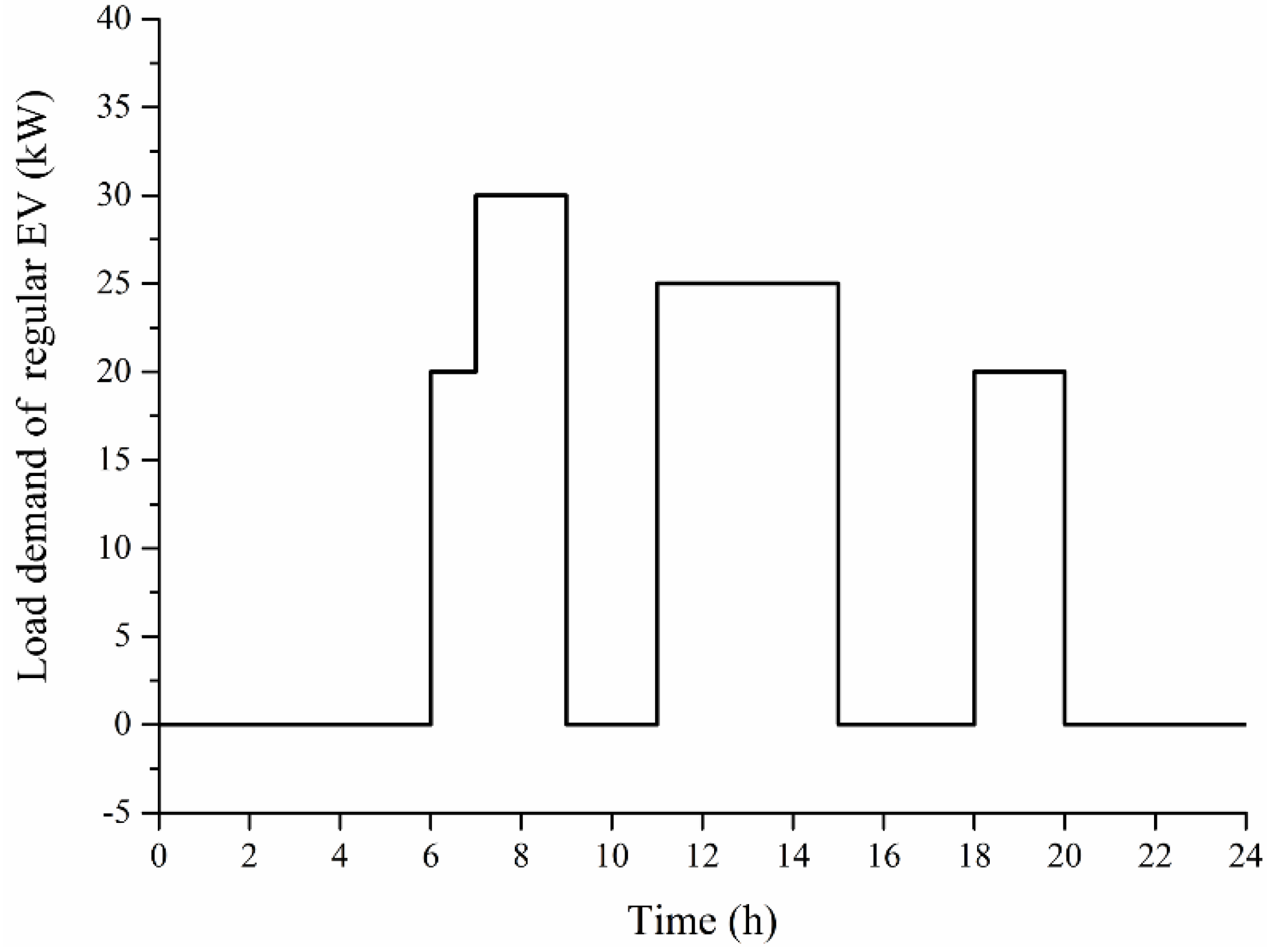
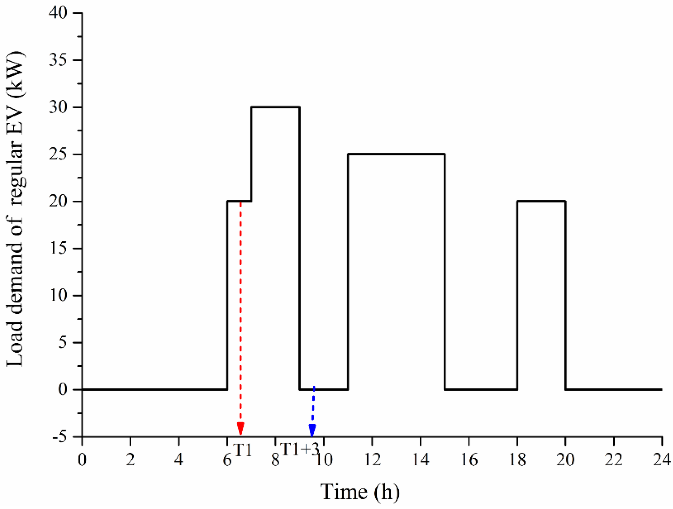
The departure time of regular EVs is arranged according to a dispatch table, and the daily trip distance is almost always the same. Charge and discharge do not occur while the vehicle is running, and are only implemented during some specified outage time.
Figure 1 shows the daily load curve of a regular EV, which also reflects the specified outage time and work time of the EV. During the times from 6:00–9:00, 11:00–15:00 and 18:00–20:00, the EV shows load performance and it is unable to charge and discharge. During the times 20:00–6:00, 9:00–11:00 and 15:00–18:00, the EV shows battery performance, PHEVs can exchange power with the grid in two-way mode and BEVs will store abundant electricity. EVs flexibly determine the charging start instant to avoid an overlap with peak load. Unlike BS, regular EVs cannot achieve real-time charging and discharging according to a power difference between power output and load demand. This is because of the constraints of their battery or load performance in the load curve. The power difference is defined as Δ
P:
Figure 1.
Daily load curve of a regular EV.
Figure 1.
Daily load curve of a regular EV.
2.1.1. ΔP > 0 Stage
At the Δ
P > 0 stage, if the EV has battery performance, PHEVs and BEVs can charge power. Considering the BS, the three charging objects consume power according to a certain proportion. If an EV has load performance, then only the BS can charge power, and PHEVs and BEVs consume power stored earlier. The charging expression can be formulated as:
The residual power of a BS is:
The residual power of a PHEV is:
The residual power of a BEV is:
With load performance, the BEV and PHEV have the possibility of electricity exhaustion. During the period of Δ
P > 0, if
, a BEV does not run out of electricity, and the interruption times and interruption durations of EVs will not be affected; As shown in
Figure 2, if
at time
T1, this shows the BEV has used up its stored power, and the paper requires the BEV to charge at that moment. The typical charging time of a BEV is 3 h, so the interruption duration is 3 h and the interruption times should add one. This interruption analysis for BEVs also applies to PHEVs.
Figure 2.
Daily load curve of regular EVs.
Figure 2.
Daily load curve of regular EVs.
The actual charged power of EVs are:
2.1.2. ΔP < 0 Stage
At the Δ
P < 0 stage, if an EV has battery performance, PHEVs and BSs can discharge power to the grid. If an EV has load performance, PHEVs and BEVs consume power stored earlier. The discharging expression can be formulated as:
The residual power of a BS is:
The residual power of a BEV is:
The residual power of a PHEV is:
During the period of ΔP <0, a PHEV should firstly meet the load demand, then consider discharging. If
, discharging is feasible, otherwise PHEV does not discharge. If
at time T1, this shows the BEV has used up its stored power, and the BEV must be charged at the moment. The charging time of a BEV is 3 h, so the interruption duration of the EV is 3 h and the interruption time adds one. The interruption analysis for BEVs also applies to PHEVs.
2.2. Ruleless EVs in CPGS
The statistical model of charging load and discharging capacity for a single ruleless EV can be built according to some probability distribution of sampling objects. On the basis of the central limit theorem, the statistical model for multiple EVs is superposition of a single EV, then the Monte Carlo method is used to simulate the charge and discharge curve. The main affecting factors included in the statistical model are: (1) battery characteristics, including battery type, rated capacity and charging profile; (2) travel behavior, including traveling start time, trip distance and traveling end time; and (3) recharging mode, including slow charging, quick charging and battery switching.
This paper uses some hypotheses: (1) the specific power consumption is constant; (2) each EV is independent; (3) the same type of batteries have the same charging characteristics; (4) the initial SOC on the first day is 100%; (5) the daily trip distance and traveling start time are independent; and (6) the initial SOC and charging start instant are independent.
2.2.1. Daily Trip Distance and Initial SOC
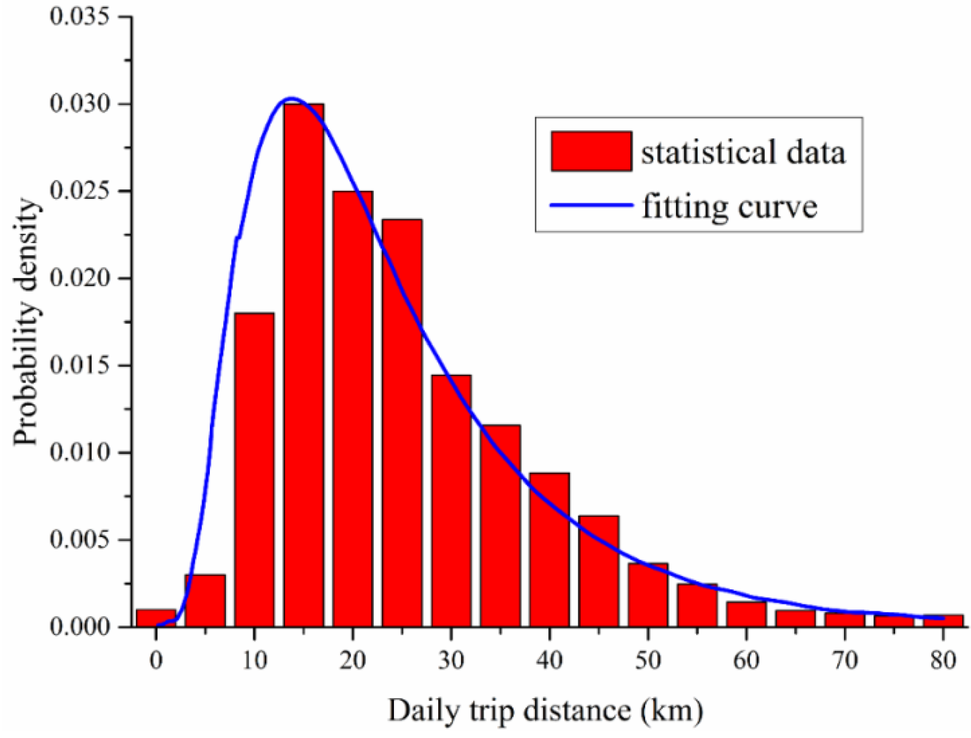
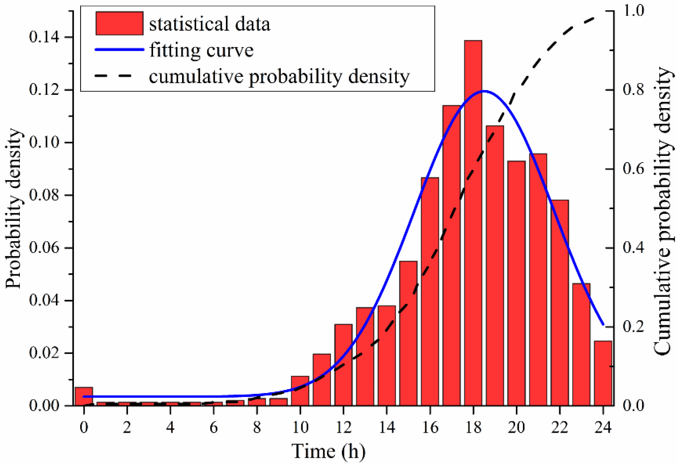
Based on general available information about private vehicle travel in 2013 [
20], the daily trip distance probability distribution is shown in
Figure 3. After normalization processing, the statistical data are fitted to a lognormal distribution, with zero probability of occurrence of all negative distances, and a “tail” extending to infinity for positive distances. The probability distribution function (PDF) for daily trip distance can be expressed as:
where μ is the mean, and σ is the standard deviation of the probability function. The mean of the distribution is 25.4 miles and the standard deviation is 11.3 miles.
Figure 3.
The daily trip distance.
Figure 3.
The daily trip distance.
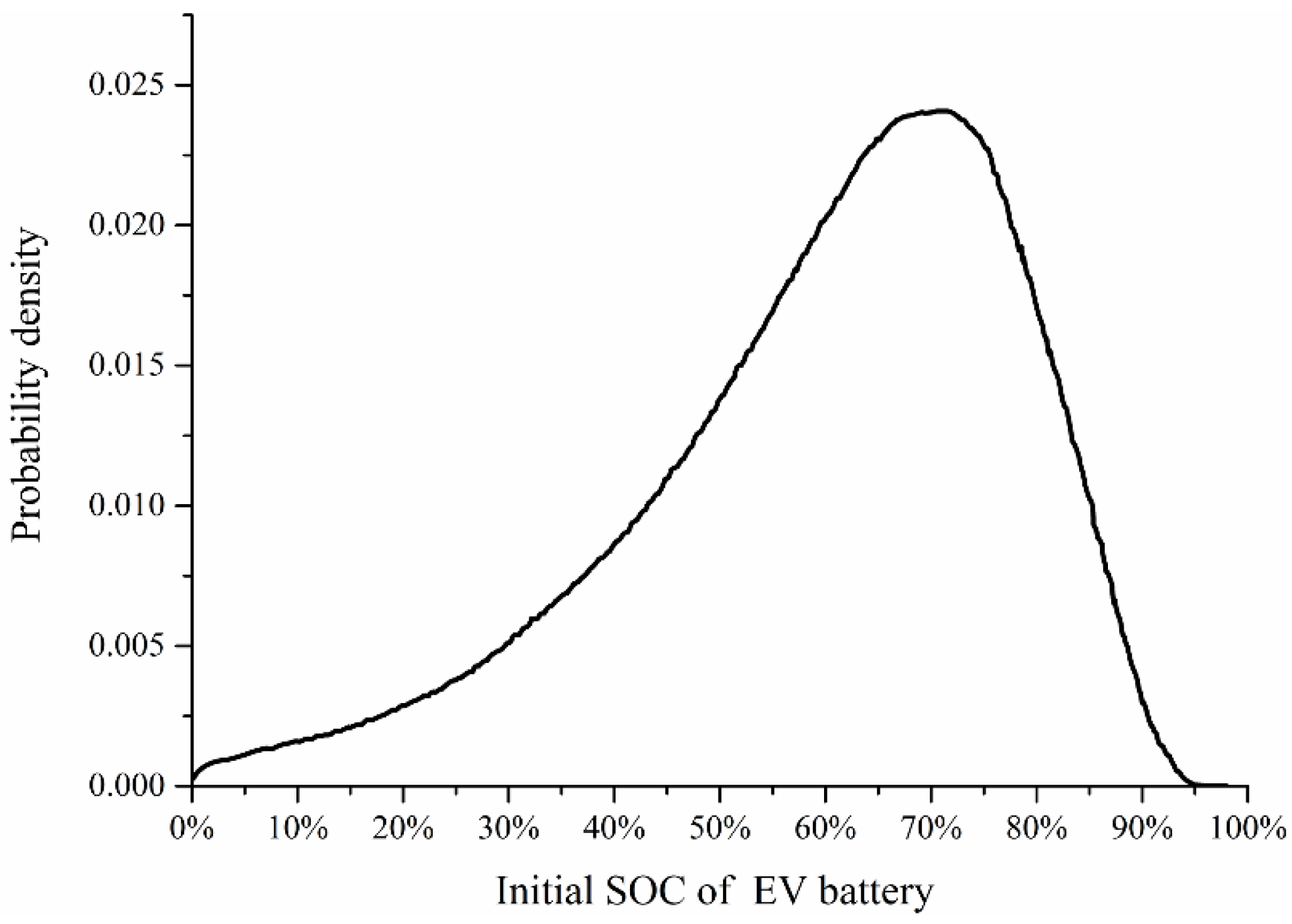
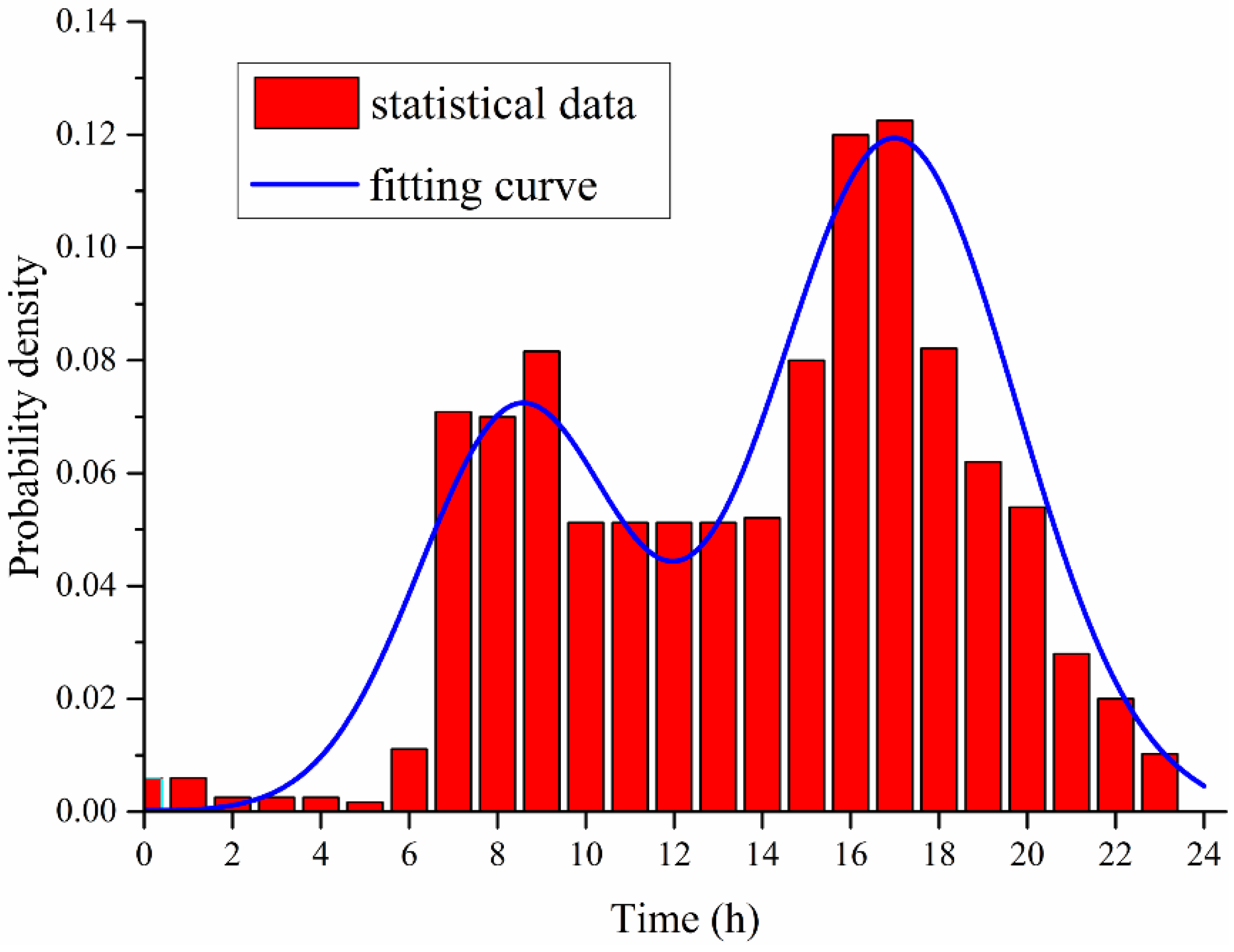
The initial SOC of the an EV battery is random due to the SOC after its last charging and total trip distance since the last charge. Considering the average daily trip distance, the SOC at the beginning of a recharge cycle (residual battery capacity) can be formulated as:
In the paper we define the EV recharge power after two days travel, so
h = 2. The PDF of initial SOC after two days travel can be derived from Equations (14) and (15), and expressed as:
Figure 4 shows the probability distribution of initial battery SOC after two days of travel.
Figure 4.
The probability distribution of initial battery SOC.
Figure 4.
The probability distribution of initial battery SOC.
2.2.2. Battery Characteristics
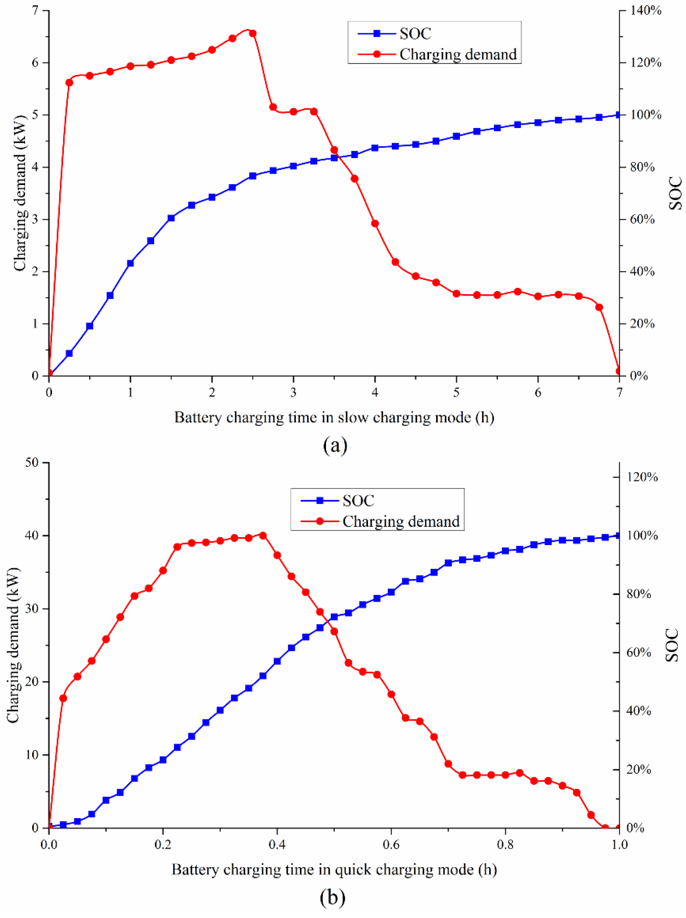
Lead-acid, lithium and NI-MH batteries are widely used in EVs. Due to their higher self-discharge rates and shorter service life, NI-MH batteries are mainly used for hybrid electric vehicles. With reliable performance, low cost and mature technology, lead-acid batteries still dominate in market share. Because of their small size, high power density, high voltage, low self-discharge and low resistance, lithium batteries are the developing trend for future EVs. The GM EV1 is introduced to analyze the charging demand and discharging capacity of EVs in this paper. The GM EV1 has a 27.19 kWh capacity lead-acid battery. The charging demand and related battery SOC profiles of a lead-acid battery in slow and quick charging mode are shown in
Figure 5a [
21] and
Figure 5b [
22].
Figure 5.
Charging profiles of the GM EV1 battery (lead-acid) (a) in slow charging mode and (b) in quick charging mode.
Figure 5.
Charging profiles of the GM EV1 battery (lead-acid) (a) in slow charging mode and (b) in quick charging mode.
To facilitate the numerical calculation, the charging demand
CD, battery SOC
S and total charging time
T are discretized. The discrete values can be expressed as:
where Δ
t = 0.5 h and
N = 14 in slow charging mode, Δ
t = 0.2 h and
N = 5 in quick charging mode.
There are one-to-one correspondences between
CDi and
Ti as well as between
Si and
Ti; the one to one mapping relationships can be built and expressed as:
There is also one-to-one correspondence between
CDi and
Si; the one to one mapping relationship can be expressed as:
Based on the mapping relationship between discrete data, the probability distribution of
CDi can be derived from the probability distribution of
Si:
If a EV battery with initial SOC
Si needs to recharge, according to the mapping relationship between
Si and
Ti, the charging time is:
where
tci is the charging time from SOC =
Si;
Tm is 7 h in slow charging mode and 1 h in quick charging mode. Substituting Equation (21) into Equation (18) and changing variables from
Ti to
tci, the mapping relationship between charging time
tci and initial SOC
Si is obtained as:
The probability distribution of
tci can be derived from the probability distribution of
Si:
2.2.3. Charging Start Instant
Charging start instant is a critical random factor to analyze the charging demand of EVs. Recharging mode affects the charging start instant; this paper introduces three recharging modes: slow charging, quick charging and battery switching.
A. Slow Charging
Slow charging uses a lower power charging facility to complete charging; this is suitable for parking lots in the community. Due to the longer charging time, drivers usually recharge EVs when they arrive home after their last trip of the day, so the charging start instant approximately equals the end time of the last trip. According to statistical data [
23], a probability distribution of end time of last trip is developed in this paper, as shown in
Figure 6.
Figure 6.
Probability distribution of the end time of the last trip.
Figure 6.
Probability distribution of the end time of the last trip.
The PDF for charging start time illustrated by
Figure 6 can be expressed as:
where
= 17.6,
= 3.4.
B. Quick Charging
Quick charging uses a large current to charge the EV, which is usually 0.8–1 C, so this charging mode can complete full charging within a short time. Just like gasoline cars fuel up at gas station, EVs recharge power at quick charging stations (QCS), Because EVs’ arrival time at QCS are random, this paper defines it as a random variable following a certain probability distribution. After the normalization of the statistical data from the Statoil Bärbyleden-Oppsala gas station [
24], the arrival time distribution is shown in
Figure 7. It is assumed that the EV arrival time distribution at a QCS is same as the vehicle arrival time distribution at this gas station. This paper supposes that EVs recharge power as soon as they arrive at a QCS, so with the help of data fitting, the PDF of charging start instant in quick charging mode can be expressed as:
Figure 7.
The distribution of vehicle arrival time at QCS.
Figure 7.
The distribution of vehicle arrival time at QCS.
C. Battery Switching Mode
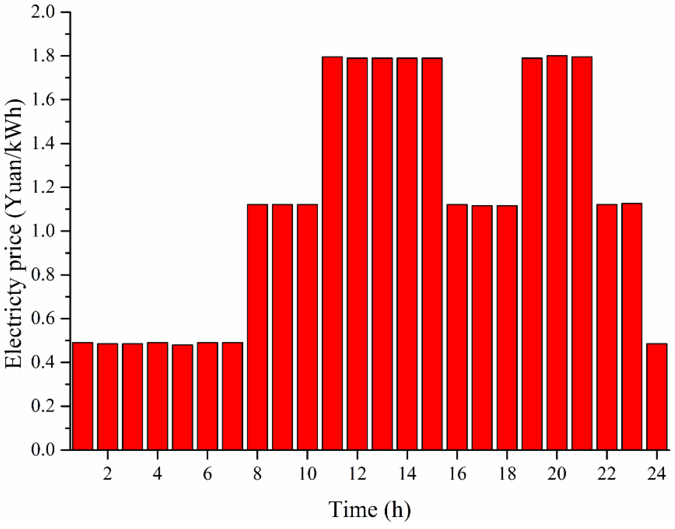
Battery switching is the quickest and most convenient way to recharge EVs, by replacing empty batteries in a timely way with full batteries previously charged at a battery switch station (BSS). Due to the quick operation, this paper ignores the time consumption of battery replacement, so the arrival time at the BSS has the same probability distribution as at a QCS.
According to the time-of-use power price in
Figure 8 [
25] and daily load curve, a BSS provides a reasonable charge and discharge plan. The BSS recharges the replaced empty batteries in slow charging mode at low cost and low load, which can reduce the power purchase cost and avoid “peak load superposition”. BSS makes positive contributions to peak load shifting and reduce the valley-to-peak and variance of daily load curves. According to objective functions and constraint conditions, a BSS determines the charging start instant and discharging instant. The objective functions and constraint conditions are expressed as:
Considering the charging time of an empty battery, the BSS should optimize its operation scheme during the charging progress to meet the battery switching needs when the charging time is finished:
Figure 8.
Time-of-use power price.
Figure 8.
Time-of-use power price.
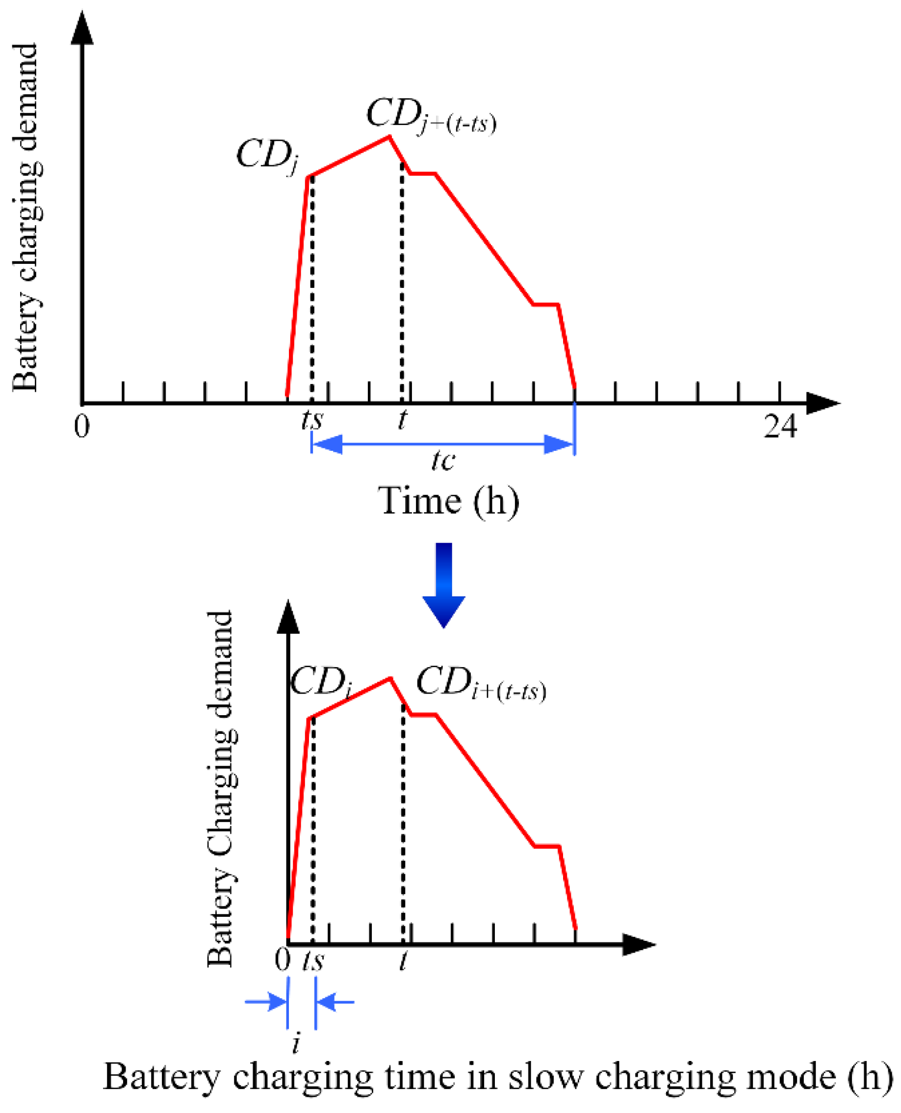
2.2.4. Charging Load of One EV
Figure 9 shows a schematic of a single EV which starts charging at time
ts with a residual battery capacity
CDts and operates at power level
CDt at a later time
t.
Figure 9.
Schematic of charging a single EV battery.
Figure 9.
Schematic of charging a single EV battery.
According to Equation (18) denoting the mapping relationship between charging demand and charging time, the charging time related to the
CDts is
Ti, and the charging time related to
CDt is
Ti + (
t ‒
ts), so the term
CDt can also be expressed as
CDTi + (t ‒ ts). The charging load of a single EV at time
t can be expressed as:
where α
t is the charging state variable at time
t, α
t = 1 represents the EV is being charged and α
t = 0 represents that the EV has completed charging or does not start charging.
The probability distribution of α
t can be expressed as:
where
is the joint PDF of the charging start instant and charging time.
In this paper, it is assumed that the charging start instant and charging time are independent for each EV, moreover
tc has the same probability distribution as the initial SOC, according to Equation (23), so
Fts,tc can be formulated as:
where
,
and
are PDF of charging start instant, charging time and initial SOC, respectively.
The probability of one EV is being charged at time
t and operating at power level
CDt can be mathematically expressed as:
According to Equation (20), the
CD has the same probability distribution with initial SOC, so Equation (32) can be expressed as:
The expectation (mean) μ(
CD) and standard deviation σ(
CD) at any time can be calculated. The following equation gives the mathematical expectation of the charging demand at time
t for an individual EV battery:
2.2.5. Charging Demand of Multiple EVs
The sum of charging demands of each EV can be used to represent the total charging demand. The charging demand of each EV contains
n independent and identically distributed random variables
P1,
P2,…,
Pn. Every variable has finite values of expectation
and variance
,
i = 1,…,
n, where
n is the number of battery chargers. The central limit theorem states that as the sample size increases (becomes sufficiently large), the distribution of the sum of these random variables approaches a normal distribution with mean
and variance
, irrespective of the nature of the original probability distribution. As a result, the charging demand of multiple EVs at instant
t is given as:
2.2.6. Discharging Capacity
Drivers search for the nearest discharge pile and consume a lot of time to complete discharging. In addition, drivers should take the electricity price, current stored power and power demand of their next travel into consideration to make more profits. It is observed that discharging is inconvenient for single EVs, so EVs in quick and slow charging mode do not discharge to the grid. BSS can flexibly determine the discharging start instant and capacity under the global optimization objects; the specific explanation is given in Equations (26) and (27).
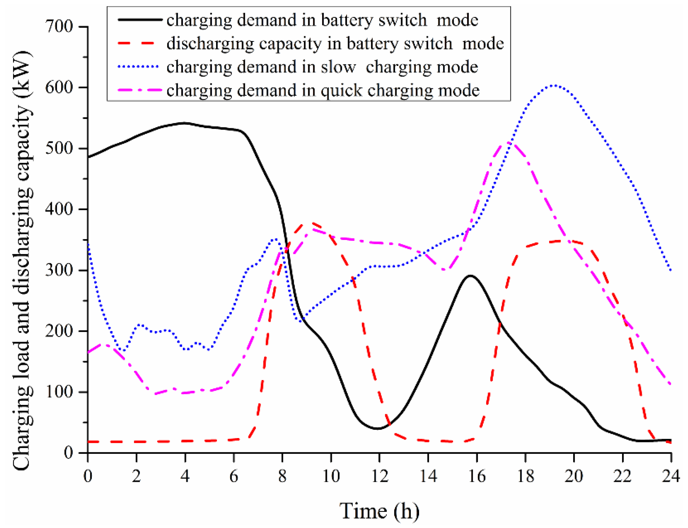
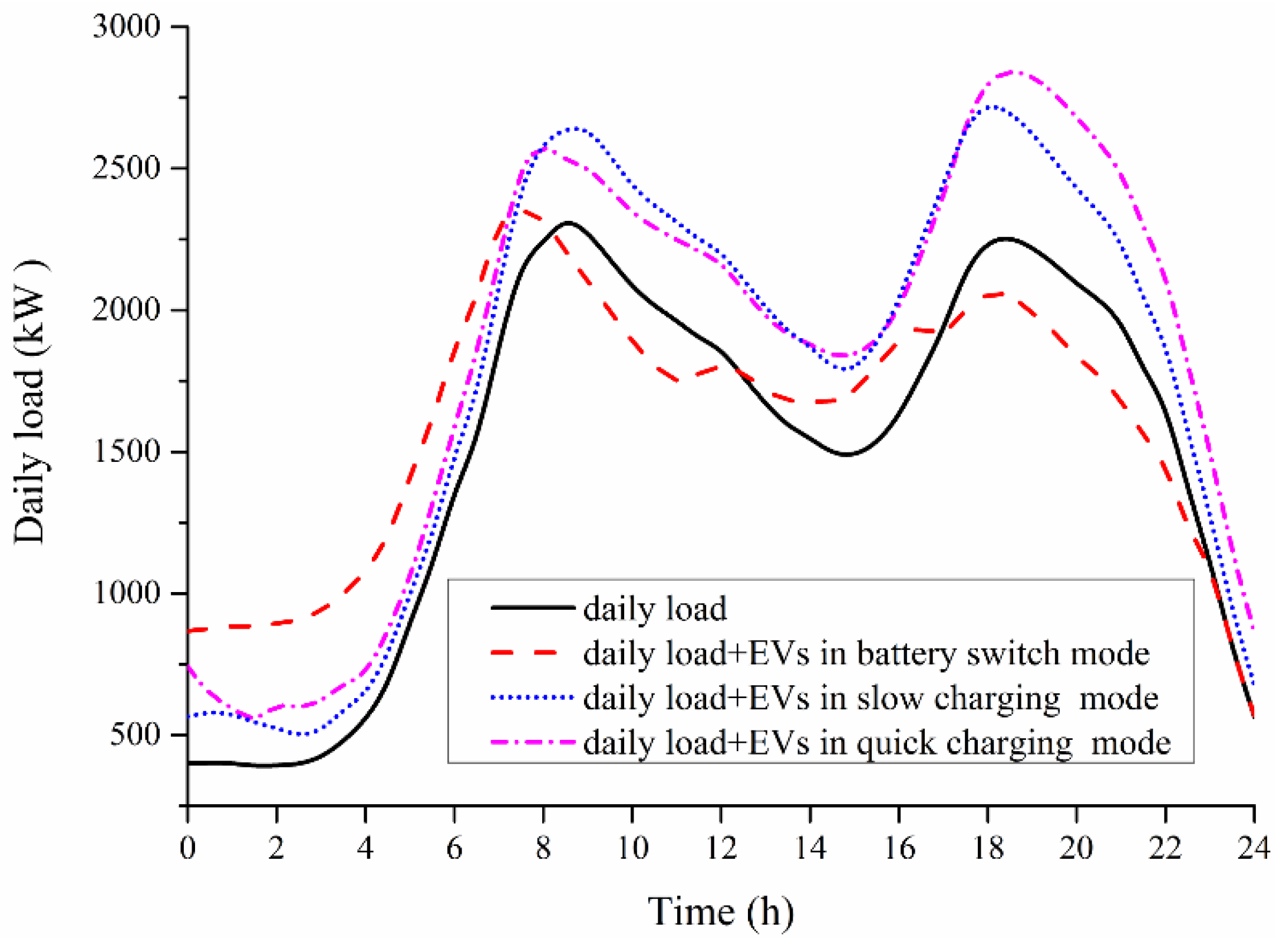
Based on the probabilistic model and charge and discharge optimization model under discussion, the Monte Carlo method is introduced to simulate the charging load and discharging capacity of ruleless EVs, The covariance coefficient of charging load and discharging capacity is defined as the convergence condition. The resultant curves of charging load and discharging capacity in three recharging modes are shown in
Figure 10. In addition,
Figure 11 intuitively reflects the influence on daily load curve caused by EVs in these three recharging modes.
Figure 10.
The charging load and discharging capacity in three recharging modes.
Figure 10.
The charging load and discharging capacity in three recharging modes.
Figure 11.
The daily load curve before and after EVs are introduced.
Figure 11.
The daily load curve before and after EVs are introduced.
2.2.7. Power Supply Time During Islanding
Based on the charging load and discharging capacity of EVs, the power supply time during islanding of a CPGS including BS, DG and ruleless EVs, can be expressed as:
The residual BS power is:
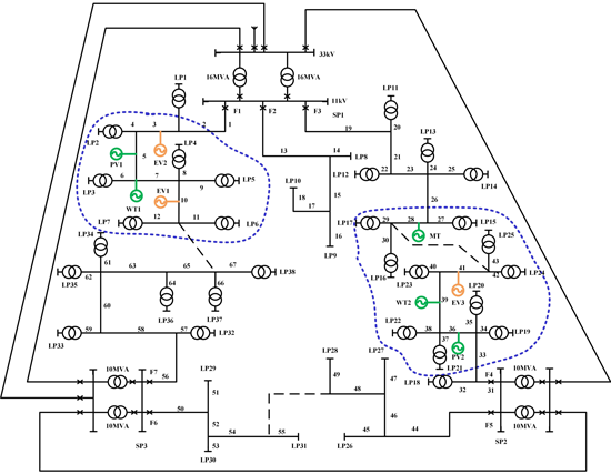
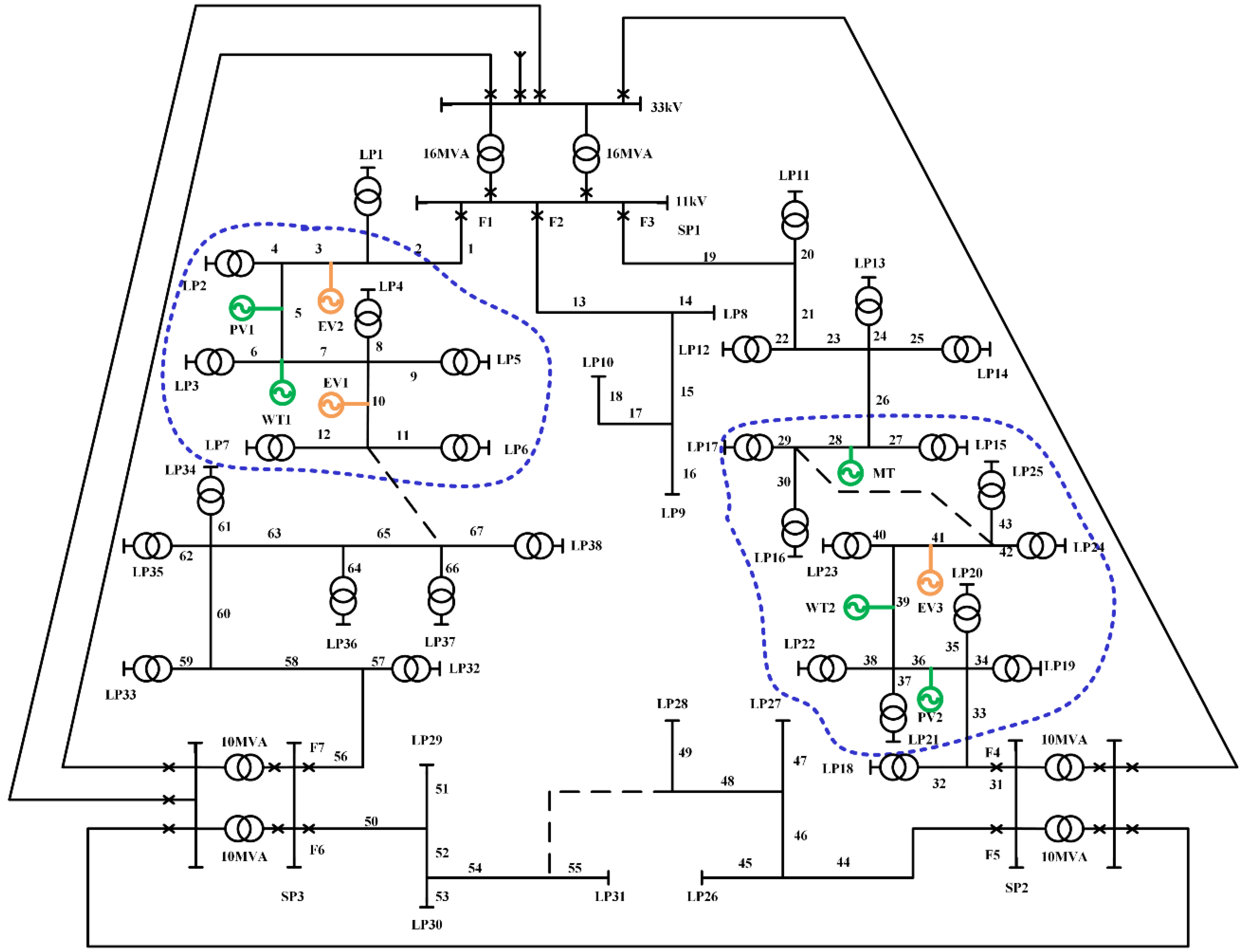
4. Study Case
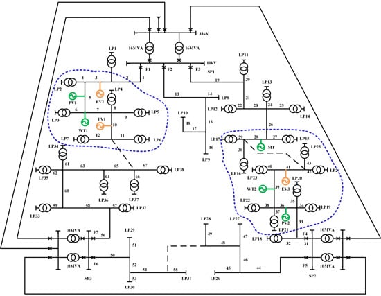
This section introduces an improved RBTS-Bus 4 test system to evaluate the reliability of a distribution network including EVs, BS and DG. Reference [
27] offers the reliability parameters of all elements and load parameters used in the case. The λ of lines and cables can be found in Table 6 of reference [
27] , the λ of transformers can be found in Table 4 of reference [
27], μ of all elements is calculated based on
r in Table 5 of reference [
27]. As shown in
Figure 12, the five DGs, three EV congruent points and two BSes access the RBTS-Bus from two microgrids.
Figure 12.
The improved RBTS-Bus 4 test system.
Figure 12.
The improved RBTS-Bus 4 test system.
The rated capacity of the DG and BS are 20 kW and 10 kW, respectively. The number of regular EVs and ruleless EVs is 1000 in total. The paper does not consider the fault rate of DG, BS and EV, and supposes that the microgrid can successfully switch to the island state every time. SAIFI, SAIDI, ASAI and EENS are selected as evaluation indexes for system reliability. The evaluation algorithm is applied to perform the reliability evaluation according to the following ten scenarios. The ten scenarios suppose different elements combination in distribution network to study influence on system reliability caused by BS capacity and V2G technology, driving behavior, recharging mode, penetration of EV:
- (1)
Only DG.
- (2)
DG and BS.
- (3)
DG, BS and regular EVs including only BEVs.
- (4)
DG, BS and regular EVs including only PHEVs.
- (5)
DG, BS and regular EVs in which the proportion of BEVs and PHEVs are 50% and 50%.
- (6)
DG, BS and ruleless EVs which use slow charging.
- (7)
DG, BS and ruleless EVs which use quick charging.
- (8)
DG, BS and ruleless EVs which use battery switch.
- (9)
DG, BS and ruleless EVs in which the proportion of quick charging, slow charging and battery switch vehicles are 40%, 40% and 20%.
- (10)
DG, BS and EVs in which the proportion of regular EVs and ruleless EVs are 50% and 50%.
Many studies have shown that DG can improve system reliability and the DG location and size have different influences on the system reliability, so the paper does not make any further study on DGs and the research focuses on the change trends of system reliability from five aspects: BS capacity and V2G technology, driving behavior, recharging mode and penetration of EVs.
(1) Battery storage capacity
As shown from scenario (1) and (2) in
Table 1, the BS also can improve system reliability. According to the description of CPGS, when Δ
P > 0, DGs produce sufficient power, BS with BEVs and PHEVs can store extra power together. If Δ
P < 0, the BS will discharge power to LI to relieve or solve the power shortage in the island. This measurement can decrease interruption times and interruption duration of LI.
Table 1.
System reliability index comparison in different system scenarios.
Table 1.
System reliability index comparison in different system scenarios.
| Scenario | System Reliability Index |
|---|
| SAIFI | SAIDI | ASAI | EENS |
|---|
| (1) | 0.3614 | 3.4582 | 0.9851 | 64.325 |
| (2) | 0.3548 | 3.1254 | 0.9862 | 60.641 |
| (3) | 0.3574 | 3.2316 | 0.9857 | 61.472 |
| (4) | 0.3541 | 3.1084 | 0.9868 | 57.145 |
| (5) | 0.3552 | 3.1854 | 0.9864 | 59.263 |
| (6) | 0.3586 | 3.1842 | 0.9859 | 62.164 |
| (7) | 0.3601 | 3.2645 | 0.9854 | 63.486 |
| (8) | 0.3425 | 3.1022 | 0.9971 | 55.583 |
| (9) | 0.3573 | 3.1201 | 0.9955 | 59.457 |
Table 2 shows that a larger storage capacity can decrease SAIFI, SAIDI, EENS and increase ASAI, and provide more reserve capacity for the distribution system. The total DG generation limits the maximum power that can be stored in a BS, so if the storage capacity continues to increase, the BS will make no use or insufficient use of this excessive storage capacity, and the system reliability increase will approach a bottleneck. In the test system, we find the optimal BS capacity is 220 kW, which can achieve optimal system reliability.
Table 2.
System reliability index comparison on different BS capacity.
Table 2.
System reliability index comparison on different BS capacity.
| BS Capacity | SAIFI | SAIDI | ASAI | EENS |
|---|
| 100 kW | 0.3548 | 3.1254 | 0.9862 | 58.641 |
| 200 kW | 0.3433 | 3.1114 | 0.9875 | 58.027 |
| 300 kW | 0.3404 | 3.1080 | 0.9880 | 57.814 |
| 400 kW | 0.3384 | 3.1064 | 0.9883 | 57.759 |
(2) V2G technology
Scenarios (2) and (3) in
Table 1 illustrate that BEVs accessing the distribution network worsen SAIFI, SAIDI, EENS and decrease ASAI from 98.62% to 98.57%. Without V2G, the BEV is a special load, so its access will raise the load demand and maximum load’s utilization hours, which increases the number of loads affected by a fault and reduces the system reliability.
Scenarios (2) and (4) show that PHEVs significantly shorten the SAIDI and EENS, as EENS goes down to 57.145 MW·h from 60.641 MW·h and SAIDI drops to 3.1084 h from 3.1254 h. V2G technology achieves the two-way interaction between the distribution network and PHEVs. PHEVs can play a battery role in an island, and restore power to partial important loads. Compared to scenario (3), the ASAI increases to 0.9868 from 0.9857 in scenario (4), which shows V2G technology improves the system reliability.
CPGS dispatch power to BEVs, PHEVs and BS according to the performance of EV and ΔP, and thus minimize the load loss. V2G technology adds an interactive pathway between EVs and the grid, it has a larger influence on EVs at ΔP < 0, when the PHEV can discharge power to an IL, but BEVs are unable to supply load. The large-scale application of V2G technology in PHEVs can improve energy efficiency and help relieve the power shortages at times of peak load, so system reliability is much improved. Ruleless EVs in quick charging and slow charging mode do not discharge to the grid, and do not adopt V2G technology. The ruleless EVs in battery switch mode make full use of V2G technology. A comparative analysis is made in scenarios (6)–(8) to reach the same conclusion that V2G technology contributes to improve the system reliability.
In addition, we define the BEV and PHEV charge power once they are running out power, so the measurement may have a negative effect on system load. The delayed charging model is feasible for optimizing lag time, synthesizing the driver experience and system reliability
(3) Driving behavior
The comparison and analysis between scenarios (3), (6) and (7) shows that under the same number and without V2G technology, regular EVs have a better effect on reducing the system interruption frequency and interruption duration than ruleless EVs in slow charging mode and quick charging mode. Without V2G, the influence of EVs is mainly on the charging load. Regular EVs charge power according to the dispatch table, so the charging load can give an advance estimate to optimize ordered charging and avoid any overlap with peak loads. The various demands of drivers make ruleless EVs have uncontrolled charge behavior, and the charging load easily meets the peak load. As shown in
Figure 1 and
Figure 11, there is a small overlap between the load demand of regular EVs and the daily peak load, and the load demand of regular EV mostly fill valley of daily load. The
Figure 10 and
Figure 11 indicate the ruleless EVs in slow charging mode will increase the nightly peak load, while ruleless EVs in quick charging mode will increase the all-day peak load. Based on the advantages of regular EVs, CPGS can set a reasonable dispatch table to avoid any overlap with peak loads.
Under the same number and with V2G technology, ruleless EVs have a larger influence on any improvement of system reliability than regular EVs. The BSS can reasonably and flexibly make a charge-discharge scheme to realize peak load shifting, and the scheme is not constrained by the driving behavior of ruleless EVs. According to the description in
Section 2.1, PHEVs belonging to regular EVs cannot achieve real-time discharging, and only can discharge to load while meeting three constraints: (1) at Δ
P <0 stage; (2) the PHEV has battery performance. (3)
. During the period of Δ
P < 0, PHEVs should first meet the load demand, then consider discharging. Compared to BSS, PHEVs merely achieve a local discharging optimum, so system reliability is less improved.
(4) Recharging mode
Scenarios (6)–(8) illustrate that when EVs recharge power in battery switch mode, the SAIFI, SAIDI, EENS are all at the lowest level and the ASAI achieves the best value, the system reliability has the worst performance in quick charging mode and middle performance in slow charging mode. As shown in
Figure 10 and
Figure 11, the charging load begins to increase at 18:00 in slow charging mode, which overlaps with the nightly peak load of the daily load. The overlap exacerbates the nightly power shortage, reducing the nighttime system reliability.
As to EVs in quick charging mode,
Figure 7 and
Figure 11 show that the charging start instant overlaps the peak load time, and
Figure 10 and
Figure 11 show that the charging load and daily load have almost same peak periods, so then the distribution network will suffer the peak load superposition and increase valley-to-peak during the full day. In consideration of the limited power generation of DG in island mode, more load will suffer outage, which leads to the worst reliability among the three recharging modes. According to the optimization goals including the minimum valley-to-peak and power purchase cost, BSS provides a charge-discharge scheme. As shown in the charging and discharging curve of BSS and the daily load curve, BSS recharges the empty batteries at the time keeping away from peak load and discharges power at peak load. The flexible charge–discharge scheme can take on the functions of peak load shifting, reducing valley-to-peak variation, decreasing interruption times and duration and improving system reliability.
(5) EV penetration
With the large scale application of EVs, the high penetration of EVs will have a greater influence on system reliability. The 1000 EVs have a 4% penetration which is calculated for the percentage of residences in the network that have a EV. The work analyzes the variation tendency of reliability indexes for different penetration of EVs in scenario (10). The proportion of BEVs and PHEVs in regular EVs and the proportion of EVs in three recharging mode in ruleless EVs can be determined according to scenarios (5) and (9).
The system reliability index comparison in
Table 3 shows that a 12% penetration of EVs leads to the best system reliability. With low penetration, the charging load of EVs has a smaller influence on daily load. In addition the discharging capacity is beneficial to improve power grid load property, the system reliability shows improving trend and reaches an optimal value at 12%. By playing a battery role in islands, EVs can provide limited stored power to LI, and this has some positive effects on system reliability, but a high penetration of EVs produces more charging load, and the negative effect on system reliability is far greater than their positive effect, so the system reliability gets worse.
Table 3.
System reliability index comparison on different penetration of EV.
Table 3.
System reliability index comparison on different penetration of EV.
| Penetration | SAIFI | SAIDI | ASAI | EENS |
|---|
| 4% | 0.3614 | 3.4582 | 0.9851 | 64.325 |
| 8% | 0.3548 | 3.2254 | 0.9862 | 62.641 |
| 12% | 0.3541 | 3.1184 | 0.9868 | 59.145 |
| 16% | 0.3674 | 3.4616 | 0.9847 | 64.472 |
| 20% | 0.3687 | 3.4657 | 0.9841 | 64.681 |
5. Conclusions
(1) The paper develops a methodology to model charging load and discharging capacity of multiple EV batteries, allowing for considerations of the statistical distribution of charging start instants and needed charging times. The probability distribution of charging start instant in different recharging modes is considered in the methodology. In addition, EVs are divided into regular EVs and ruleless EVs to study influence of driving behavior.
(2) The paper proposes a CPGS to integrate DG, BS and EV in microgrids. The CPGS can take the charge and discharge curves of EVs, DG power generation and daily load into consideration to analyze the whole power supply performance. Based on the power supply time of CPGS during islanding the paper uses a Sequential Monte Carlo approach to produce a reliability evaluation of the distribution network with microgrids.
(3) A larger BS capacity can improve the system reliability and the optimal capacity should be determined according to an economic and reliability evaluation. V2G technology achieves the two-way interaction between the distribution system and EVs and helps to provide a more flexible charge and discharge scheme, with a dramatic positive effect on the system reliability. The driving behavior including start time, end time and total distance of daily driving can regulate charging load and discharging capacity that affect system reliability. With V2G technology, the regular EVs have a better effect on reducing the system interruption frequency and interruption duration than ruleless EVs, but without V2G technology, ruleless EVs will display better performance in the improvement of system reliability. In the three recharging modes, battery switching has an optimal effect on improving reliability, and its use in EV recharging is worth recommending. Quick charging has the biggest negative effect, it produces a larger impact and interference with the power grid load. In the test system, the optimal penetration of EVs is 12%, making use of peak-load shifting ability. It is vital to evaluate the EV power integration capacity in a power grid in consideration of boundary conditions for system reliability.


