1. Introduction
Small modular reactor (SMR) is a new type of nuclear reactors which may offer a flexible, safer, and cost-effective nuclear energy, as an alternative to conventional large nuclear power plants. The international atomic energy agency (IAEA) defines an SMR as a reactor with an electricity output of less than 300 MWe. SMRs are usually designed to be fabricated in a factory and then the reactor modules are transported to the designated location for installation. Recently, they have been receiving more attention, especially after the Fukushima accident in 2011, since it is relatively easy to remove the decay heat in a passive way in order to prevent Fukushima-like accidents from ever happening. Furthermore, SMRs are particularly well suited for developing countries and isolated areas with a relatively small electricity grid system due to their low capital cost and flexibility in implementation.
Despite the small size of existing water-cooled SMR cores, the volume and area required for the power conversion system are still quite significant with the steam Rankine cycle. Consequently, the whole SMR system cannot be very compact. The attractiveness of SMRs can be further enhanced if the reactor and balance of plant can be integrated all together, thereby substantially reducing the size of the entire system. If the gas Brayton cycle replaces the steam Rankine cycle, the power conversion unit can be substantially reduced and the total system can be much more compact [
1]. The closed gas Brayton cycle technologies have revived due to the technology enhancement in compact heat exchangers and turbo-machineries. In the closed gas Brayton cycle, heat exchanger are responsible for most of the total volume. Therefore, to achieve compact power conversion unit for complete modularization, compact heat exchanger technology is essential. The printed circuit heat exchanger (PCHE) is one of the most widely used compact heat exchanger for the closed gas Brayton cycles. The PCHE technology enables designs and realization of compact heat exchangers such as recuperators and pre-coolers for gas Brayton cycles.
Among the various gas Brayton cycles, the supercritical CO
2 Brayton (SCO
2) cycle has a higher cycle efficiency in the relatively low operating turbine inlet temperature range (450–750 °C) when compared to the other closed Brayton cycles using helium or nitrogen. For example, for a turbine inlet temperature of 550 °C, thermal efficiency of SCO
2 Brayton cycle is about 45%, which is significantly higher than ~37% of the helium Brayton cycle [
2]. Moreover, the size of SCO
2 cycle turbo-machineries is much smaller than that of the other closed gas Brayton cycles since fluid CO
2 above the critical point (7.38 MPa, 31.1 °C) can deliver a substantially higher power density. Previously, a large-size (2400 MWt) SCO
2-cooled fast reactor concept combined to direct SCO
2 Brayton cycle has been investigated by the Massachusetts institute of technology (MIT) [
3,
4].
Unlike the large SCO
2-cooled fast reactor in the previous studies, a compact SCO
2-cooled fast reactor is considered in the current work under the name of Korea Advanced Institute of Science and Technology (KAIST) micro-modular reactor (MMR). In the KAIST MMR, the core is directly cooled by SCO
2 and the SCO
2 power conversion system is directly driven by the coolant without any intermediate heat exchanger. As a result, both reactor core and the SCO
2 power conversion module are integrated into a single reactor vessel and the KAIST MMR can be a super-compact modular reactor [
5,
6]. Therefore, the KAIST MMR is a kind of “all-in-one” type super-compact and truck-loadable SMR. There are many supporting studies about the SCO
2 Brayton cycle for nuclear applications [
7,
8,
9]. Several research institutes around the world have already achieved electricity generation with experimental SCO
2 power conversion systems and they are trying to improve the system performances [
10,
11,
12,
13]. It is interesting to note that both fossil and renewable industries are actively developing the SCO
2 Brayton cycle in pursuit of a high-performance power conversion system.
The main objective of this study is to introduce the unique and innovative KAIST MMR concepts and perform the neutronic feasibility analysis of the MMR designs. In addition to the neutronic characterization of the MMR core, preliminary thermal-hydraulic analyses have been also performed for the core in this work. In this work, all the neutronic calculations are performed by using the Serpent code, a continuous-energy Monte Carlo code [
14], with the ENDF/B-VII.1 neutron data library.
2. Concepts of the Korea Advanced Institute of Science and Technology Micro Modular Reactor
There are four top-tier design goals for the KAIST MMR. First of all, it is required that the MMR should be all-in-one-type fully-integrated system in a single reactor vessel. The second one is that it should be super-compact and truck-loadable. The third one is a long core lifetime, which is over 20 effective full power years (EFPYs). Lastly, the fuel should be low-enriched U (LEU). The long lifetime and LEU requirements are necessary conditions for an SMR located in isolated and independent locations since the refueling will be extremely difficult and costly in such an isolated area and the fuel should be useless for diversion. It is expected that the long lifetime and LEU fuel will improve the proliferation resistance of the SMR fuel cycle.
To satisfy the first and second design goals, the MMR will be directly cooled by an SCO
2 coolant. Meanwhile, a fast spectrum core is adopted in the KAIST MMR to achieve both 20-EFPY lifetime and compact core simultaneously. Taking into account the compact and truck-loadable MMR requirement, the total weight of the MMR should lower than 260 ton. After evaluating the whole system, the maximum allowable core weight was determined to be 50 ton for the MMR system.
Figure 1 shows the schematic view of the KAIST “all-in-one” MMR system.
As shown in
Figure 1, all nuclear components of the KAIST MMR are installed in a single pressurized reactor vessel and the reactor vessel is protected by an extra strong guard vessel, thereby minimizing the probability of a loss of coolant accident in the SCO
2-cooled MMR. The system pressure and coolant temperatures are determined by taking into account the power conversion efficiency and the material compatibility in the reactor core [
5,
6].
Figure 1.
Schematic layout of Korea Advanced Institute of Science and Technology (KAIST) micro modular reactor (MMR).
Figure 1.
Schematic layout of Korea Advanced Institute of Science and Technology (KAIST) micro modular reactor (MMR).
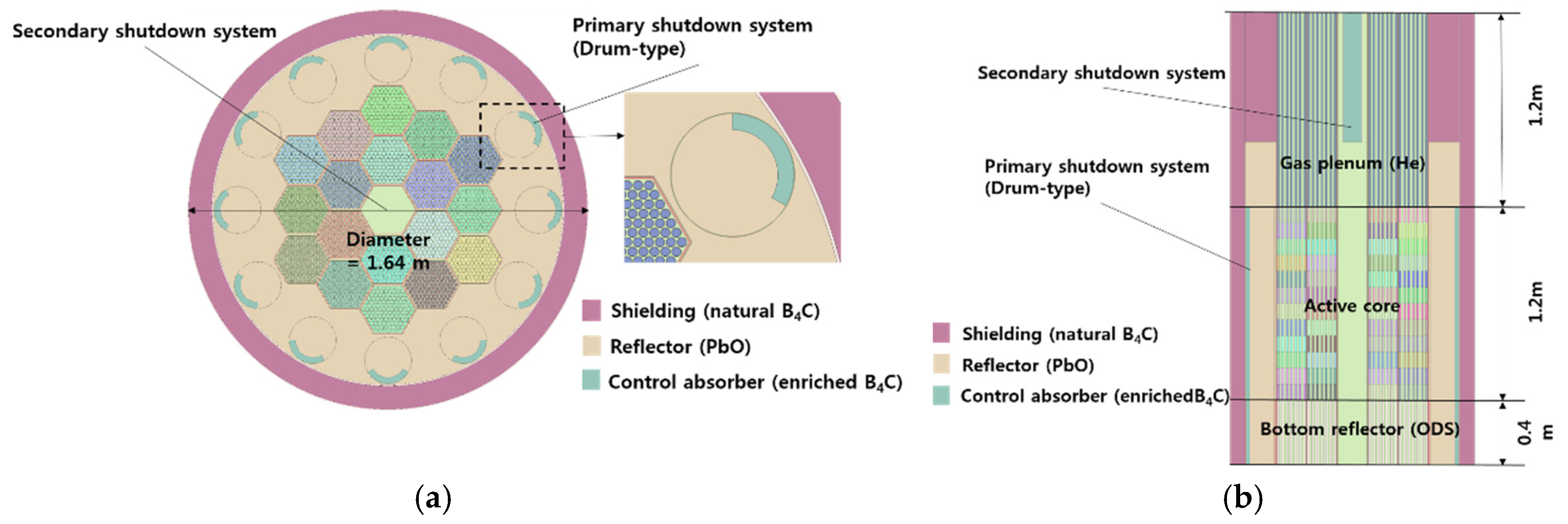
Figure 2 shows the KAIST MMR core configuration considered in this study. It consists of 18 hexagonal fuel assemblies and a reflector region housing 12 primary control drums to adjust the reactivity. It is worthwhile to note that the core size can be minimized by adopting the drum-type reactivity control system. A thick B
4C shielding layer surrounds the PbO radial reflector. In addition to the compact control drums, a conventional secondary reactivity control device is placed in the central non-fuel region. The central reactivity control system is used for ultimate shutdown of the reactor. The total weight of the core is about 39.6 ton.
Table 1 lists the major design parameters of the KAIST MMR.
Figure 2.
Radial and axial configurations of the KAIST MMR. (a) Radial configuration and drum-type control system; (b) axial configuration.
Figure 2.
Radial and axial configurations of the KAIST MMR. (a) Radial configuration and drum-type control system; (b) axial configuration.
Table 1.
Design parameters of KAIST micro modular reactor (MMR).
Table 1.
Design parameters of KAIST micro modular reactor (MMR).
| Parameter | Value |
|---|
| Rector power/lifetime | 36.2 MWth/20 years |
| Number of fuel assemblies | 18 |
| Active core equivalent radius/height | 46.58 cm/120 cm |
| Whole core equivalent radius/height | 82 cm/280 cm |
| Coolant pressure/speed | 20 MPa/6.92 m/s |
| Coolant inlet and outlet temperature | 655 K/823 K |
| Total mass of core | 39.6 ton |
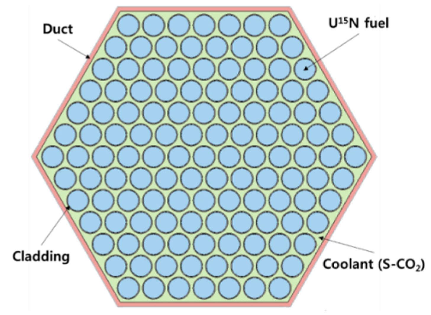
The system pressure and coolant-related parameters such as temperatures and speed have been determined through a system optimization study in view of the thermal performances. In the determination of the coolant exit temperature, the material compatibility was also accounted for. A ducted fuel assembly is adopted for the MMR core and it is comprised of 127 fuel pins, as shown in
Figure 3.
Table 2 shows design parameters of the fuel assembly and fuel rod. The fuel material is uranium mono-nitride (U
15N) and relatively large pin is utilized to maximize the fuel inventory in the compact core. The volume fractions of the fuel, coolant, and structure are 54.5%, 30.6%, and 14.9%, respectively, in a single fuel assembly. The fuel assembly design was derived through a preliminary thermal-hydraulic-coupled analysis for the MMR core in view of the core lifetime and cladding temperature,
etc.
Figure 3.
Fuel assembly configuration of the KAIST MMR.
Figure 3.
Fuel assembly configuration of the KAIST MMR.
Table 2.
Fuel assembly design parameters of the KAIST MMR. Oxide dispersion-strengthened: ODS.
Table 2.
Fuel assembly design parameters of the KAIST MMR. Oxide dispersion-strengthened: ODS.
| Parameter | Value |
|---|
| Fuel material (density) | UN (13.37 g/cc) |
| Cladding material (density) | ODS (7.2 g/cc) |
| Gap material | Helium |
| Number of pins | 127 |
| Pin diameter | 1.50 cm |
| Fuel radius | 0.69 cm |
| Gap thickness | 0.01 cm |
| Cladding thickness | 0.05 cm |
| Duct thickness | 0.3 cm |
| Inter-assembly gap | 0.25 cm |
| Pitch/diameter ratio | 1.13 |
| Wire diameter | 0.195 cm |
| Assembly pitch | 20.355 cm |
| Flat-to-flat distance | 20.105 cm |
| Fuel/coolant/structure volume fraction | 54.5%/30.6%/14.9% |
In this MMR design, the UN fuel is used in favor of its high density and superior thermo-physical properties. Nominal density of UN is 13.55 g/cm
3, which is significantly higher than that of the UO
2 ceramic fuel, 10.97 g/cm
3. It is rather comparable to the metallic U-Zr fuel in terms of effective U density in the fuel region. In addition, it has very favorable fuel properties such as high thermal conductivity of ~27.33 W/m·K at 500 °C, which is actually similar to that of a metallic fuel and a high melting temperature of ~3078 K, which is much higher than the melting temperature of metallic fuel (~1250°C). Since the UN fuel has a high thermal conductivity, its temperature during operation is much lower than that of the conventional UO
2 fuel. The combination of these traits substantially improves the operational safety margin, flexibility in reactor power maneuvers, and fuel cycle economics of the MMR system [
15].
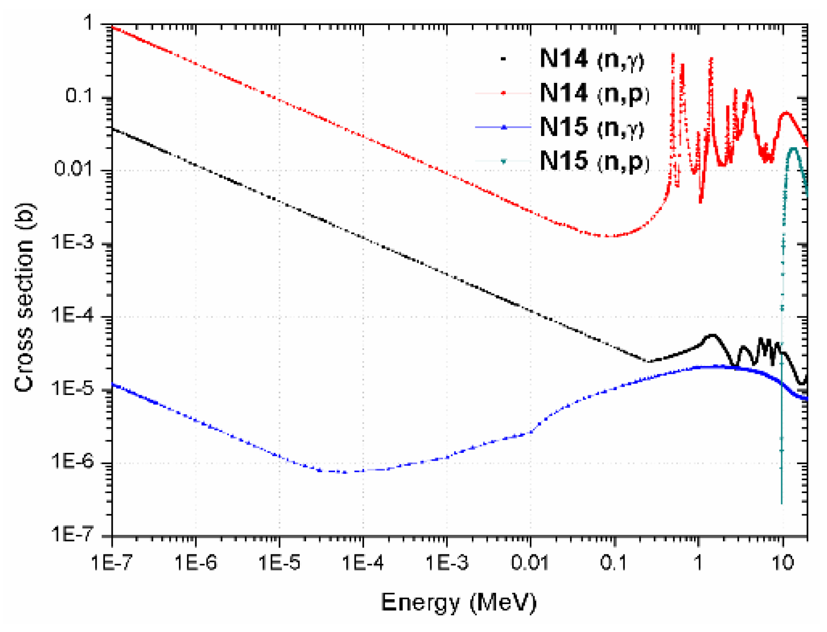
However, due to the high (n,p) cross section of
14N, nitrogen in the UN should be enriched to
15N to enhance the neutron economy.
Figure 4 shows the comparison of the (n,γ) and (n,p) cross sections between
14N and
15N based on ENDF/B-VII.0. As shown in
Figure 4,
15N has much smaller (n,
p) and (n,γ) cross sections than
14N. A sensitivity study [
6] indicates that the core lifetime with the natural UN fuel is four times shorter than that of a U
15N fuel. Meanwhile, it is known that
15N enrichment is commercially available and the most effective and feasible method is to use the heavy water separation process to obtain the initial enriched
15NH
3, and then use this as the working module for further enrichment with the laser isotope separation method [
16].
Figure 4.
Comparison of N-14 and N-15 cross sections [
17].
Figure 4.
Comparison of N-14 and N-15 cross sections [
17].
One concern in using the UN fuel is relatively high fuel swelling with burnup. In this study, it is assumed that the U
15N has a smear density of 95% to accommodate the irradiation swelling. It is expected that the average discharge burnup of the KAIST MMR is about 5% and the average fuel temperature is only about 975 K. Therefore, the fuel swelling in the MMR core is predicted to be less than 5% [
18].
The fuel and cladding chemical interaction (FCCI) is also one of the safety concerns of the nuclear reactor design. According to a compatibility study between the mono-nitride fuel with structural materials such as SS304 and SS316 in accident conditions, mono-nitride fuel is highly compatible with austenitic and ferrite-martensitic steel [
19]. Based on these observations, oxide dispersion-strengthened (ODS) steel is adopted as the cladding and structural material. It also has improved material properties such as high creep resistance up to 800 °C, when compared with SS316.[
3].
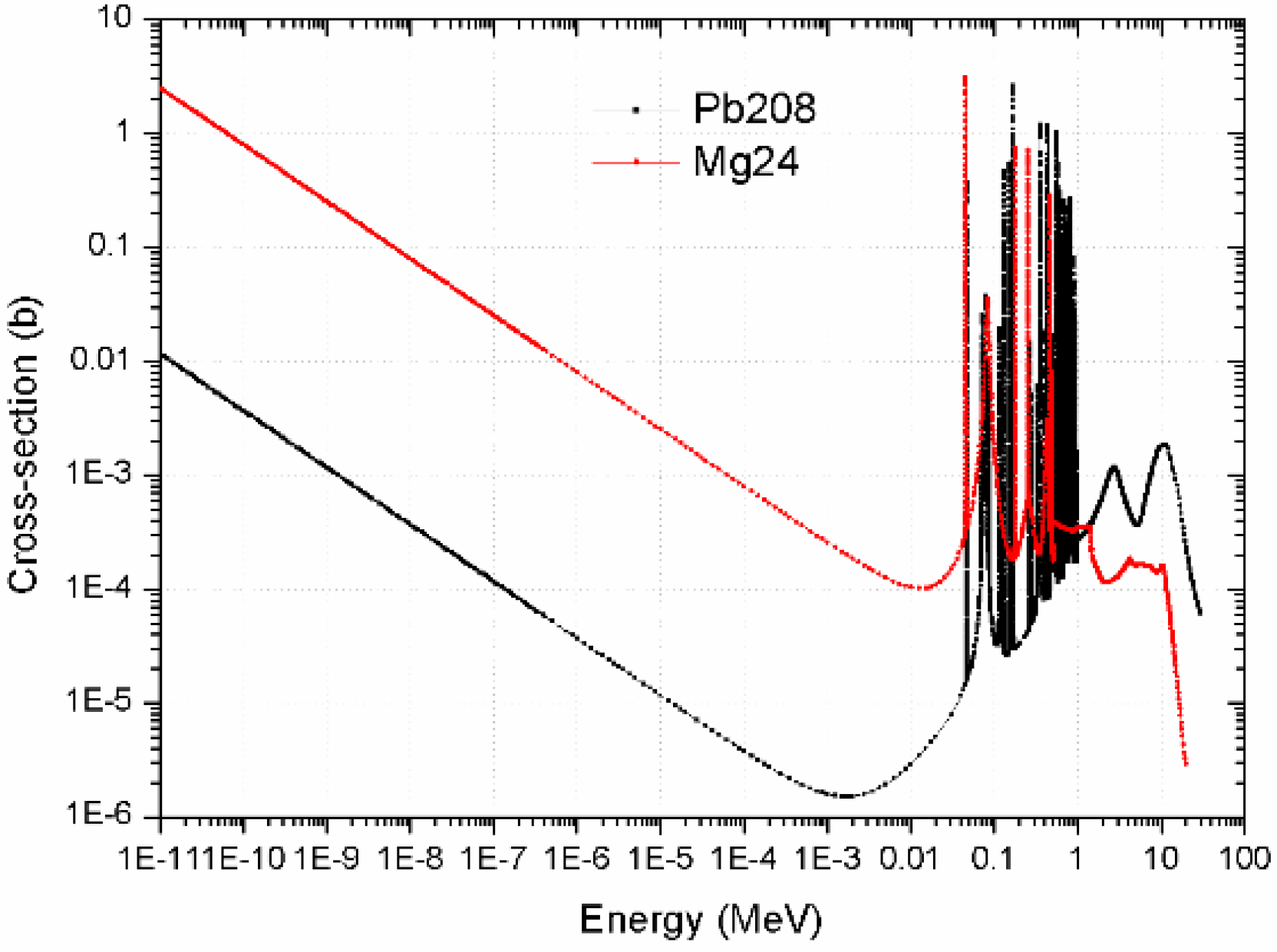
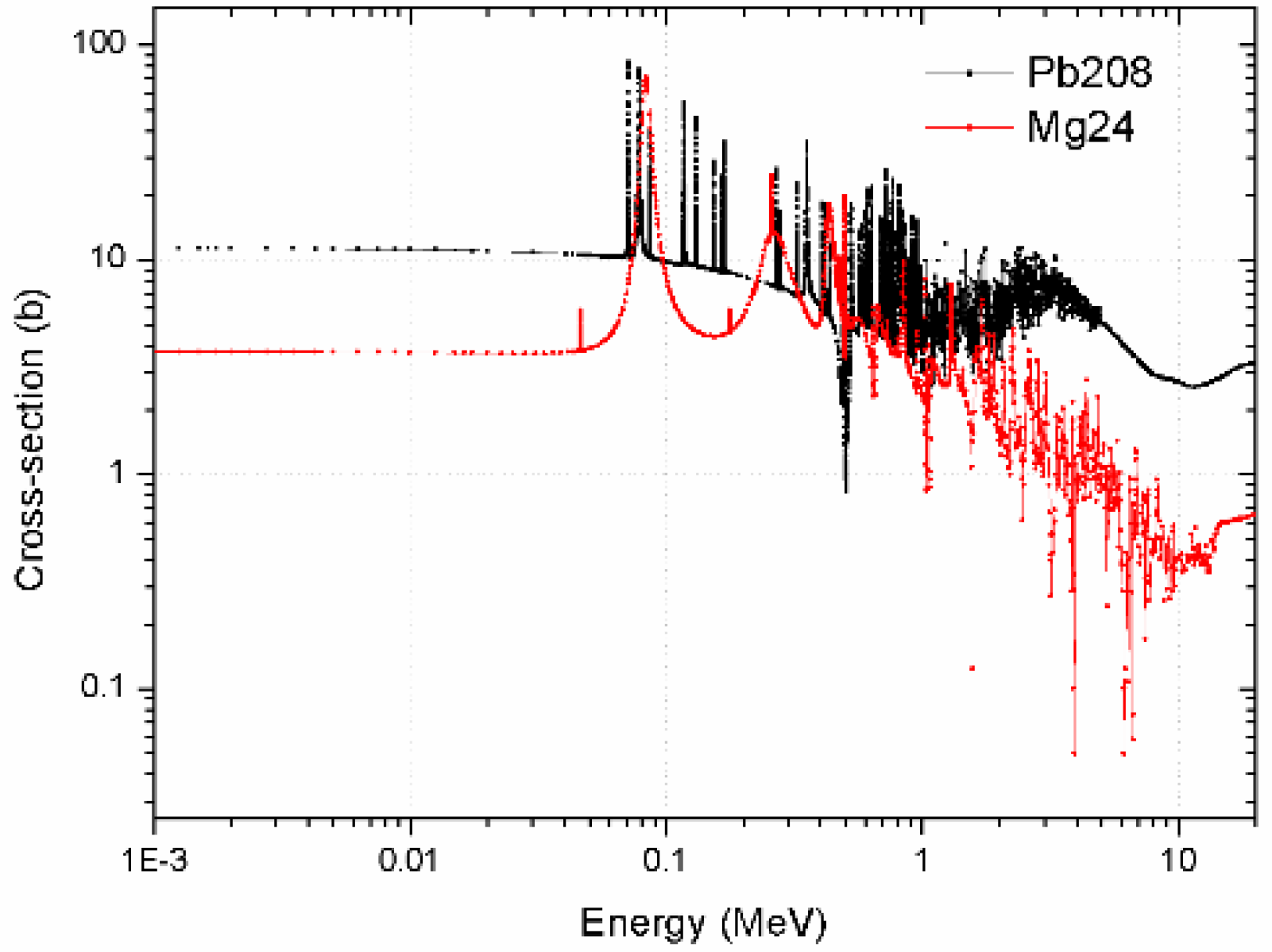
Unlike the conventional fast reactors, PbO is used as the reflector material to improve the neutron economy of the compact MMR core. Both conventional steel and MgO were also evaluated for the MMR reflector material. In particular, MgO was considered because of its relatively low density which is good for reducing the mass of the core. Although PbO is a heavy compound, but it provides a better reflector performance than MgO due to higher scattering-to-capture ratio and hard spectrum [
20].
Figure 5 and
Figure 6 show the comparison between the scattering and capture cross sections of
24Mg and
208Pb. One can note that Pb has a higher scattering-to-capture ratio compared with Mg in the fast neutron energy range. In the MMR core, the PbO reflector is contained inside an ODS canister and it surrounds the core in a cylindrical shape with an equivalent thickness of 20 cm. Then, a 10 cm-thick enriched B
4C shield is located outside of the reflector. In this work, it is assumed that the density of the B
4C shield is 70% of the theoretical density.
Figure 5.
Elastic scattering cross sections for the major isotopes of reflector material [
17].
Figure 5.
Elastic scattering cross sections for the major isotopes of reflector material [
17].
Figure 6.
Capture scattering cross sections for the major isotopes of reflector material [
17].
Figure 6.
Capture scattering cross sections for the major isotopes of reflector material [
17].
Table 3 shows the design parameters of the primary control drum system and secondary shutdown system. The absorber material is 98%-enriched B
4C for the two reactivity control systems. The density of the control absorber is assumed to be 98% of the theoretical density. In the previous study [
6] for the MMR, a moving control assembly was considered for the primary control system. It was similar to the concept of follower fuel in research reactors. The moving control assembly in the previous study consisted of absorber at the top and reflector at the bottom in order to reduce the size of the core. It was found that the core radius can be smaller with the moving control assembly, but height of the core should be increased substantially due to axial movement of the control system. For a smaller volume of the MMR core, the drum-type control system is adopted, which is typically used in compact space reactors.
As shown in
Figure 2, twelve control drums are located in the reflector region and each drum consists of an absorber plate on the surface of a rotating drum. The spanning angle for the absorber section of the control drum is 120°. The core reactivity is controlled by rotating the drums.
Table 3.
Design parameters of control drum and the central control rod.
Table 3.
Design parameters of control drum and the central control rod.
| Parameter | Control Drum | Control Rod |
|---|
| Material | 98 w/o-enriched B4C | 98 w/o-enriched B4C |
| Absorber thickness | 2.5 cm | 6.0 cm (radius) |
| Drum radius | 9.5 cm | - |
| Gap/cladding thickness | 0.1 cm/- | 0.1 cm/0.5 cm |
3. Neutronics Analysis and Characterization of the Micro Modular Reactor Core
Monte Carlo depletion analysis has been performed with the Serpent code to evaluate the reactor lifetime and safety parameters such as control drum/rod worth, stuck drum worth, fuel temperature coefficient (FTC) and coolant void reactivity (CVR). In the Monte Carlo analysis, the calculation conditions include 50,000 neutron histories in each cycle and 300 active cycles (200 inactive cycles). In fast reactors such as the current MMR, the core performances are not sensitive to the temperature profiles in the core. Therefore, the fuel, cladding and coolant temperatures are assumed to be constant at 975 K, 875 K and 750 K, respectively, in this preliminary core analyses. These temperatures were determined through a 1-D single-channel thermal-hydraulic analysis for a representative fuel channel of the core. The thermal-hydraulic-coupled neutronic analysis is not considered in this study yet. Nevertheless, a preliminary thermal hydraulic analysis will be discussed in the next section.
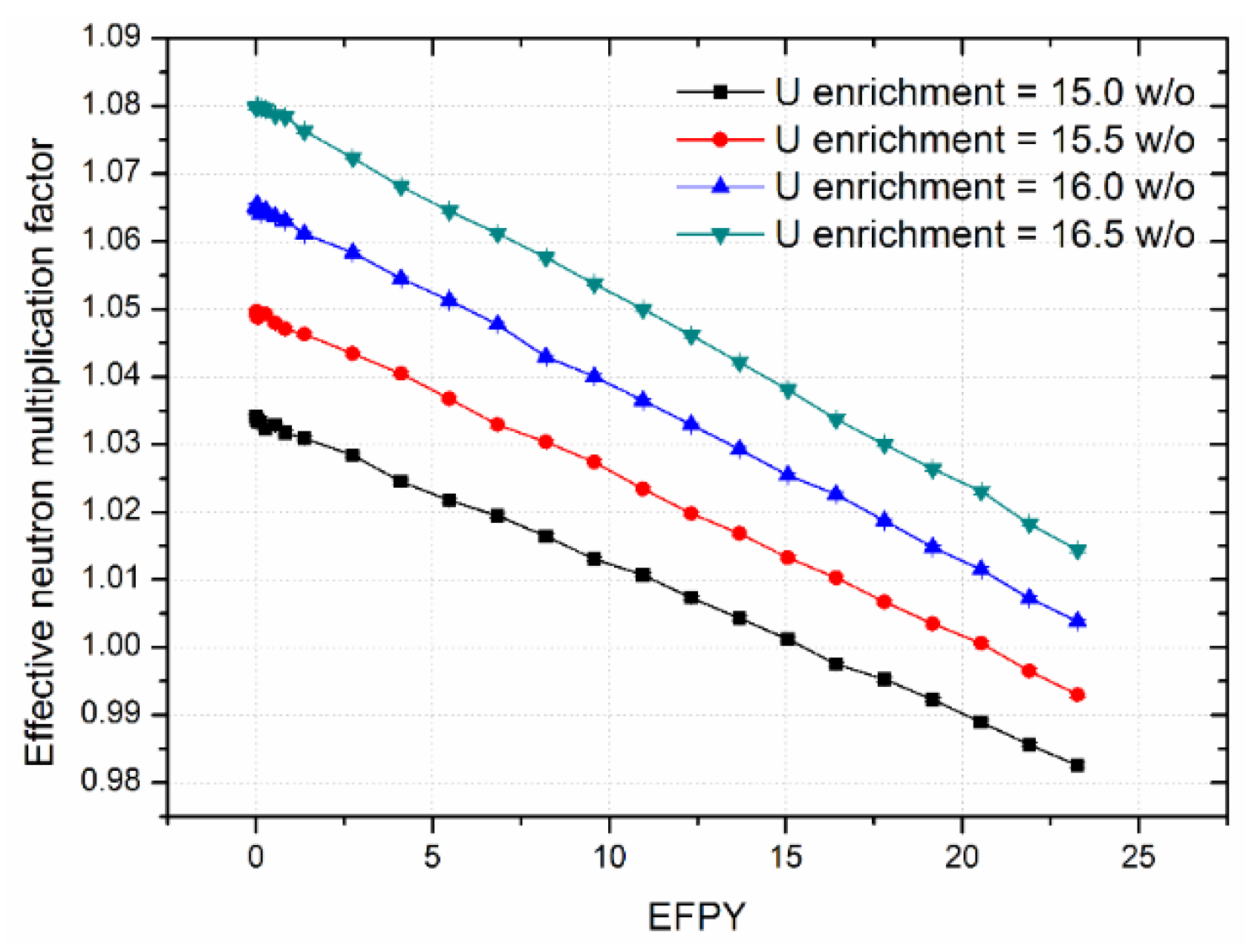
Figure 7 shows the depletion results with four different U enrichments for the U
15N fuel. Since the neutron leakage is quite high in the MMR due to the small core size, the required fuel enrichment is rather high, about 15.5%, to achieve the targeted lifetime of 20 EFPYs. The statistical uncertainty (σ) of the k-eff value is about 20 pcm in the Monte Carlo depletion calculations. It is very clear that the core reactivity rather linearly decreases with burnup in the MMR core, which is largely ascribed to a low conversion ratio of the small core. The average power density of the core is 88.23 W/cc and the averaged discharged burnup of the fuel is about 52 GWd/MTHM. For the 20-EFPY MMR core with 15.5% U enrichment, the initial excess reactivity is about 4,707 pcm. This amount of excess reactivity should be well managed by the control drums during normal operation and also a sufficiently large shutdown margin should be provided. However, the drum-type control absorber usually provides relatively small reactivity worth since it mainly depends on the neutron leakage from the core.
Figure 7.
Depletion results with different U enrichment for the MMR.
Figure 7.
Depletion results with different U enrichment for the MMR.
For a 20-EFPY lifetime of the MMR core, it is necessary to reduce substantially the excess reactivity. Unlike thermal reactors, the excess reactivity cannot be effectively managed by the burnable absorbers in fast reactors due to the hard spectrum and low capture cross sections. In the current work, to deal with the high excess reactivity, a concept of removable neutron absorber similar to the one in the Toshiba 4S [
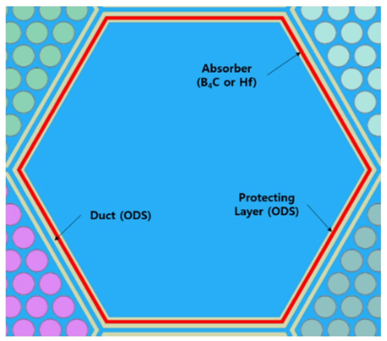
21] is introduced, which is called “replaceable fixed absorber (RFA)”. In
Figure 8, the schematic concept of the RFA is depicted,
i.e., a hexagonal absorber material is loaded into the central guide structure of the secondary shutdown system and the absorber section is designed to be replaceable, if necessary.
Figure 8.
Concept of the replaceable fixed absorber (RFA) in the MMR.
Figure 8.
Concept of the replaceable fixed absorber (RFA) in the MMR.
Two absorber materials for RFA were considered in this MMR study. One is a 2 mm-thick B4C layer and 90%-enriched B-10 is used as the absorber. The B4C density is assumed to be 70% of the theoretical density. The other is a 20 mm-thick natural Hf with 100% theoretical density. Hafnium is considered as an alternative absorber material because there can be concerns on the integrity of the B4C absorber since helium gas is produced by B-10 depletion. It is worthwhile to note that, to protect the RFA layer, a 1 mm thick inner protection layer of ODS steel is also provided. In the case of B4C absorber, it is assumed in this work that the He gas can be vented from the absorber region. It should be mentioned that the RFA is protected by the two strong ODS steel layers which is firmly fixed in the top and bottom structure of the core. The duct will be replaced with regular duct when the absorber is no longer required in the core, thus the probability of inadvertently RFA withdrawal is practically impossible.
In the current application of the RFA, the whole 20 EFPYs are divided into two 10 EFPYs and the RFA is installed at the beginning of the first-half cycle core and is removed at the end of the first–half cycle core.
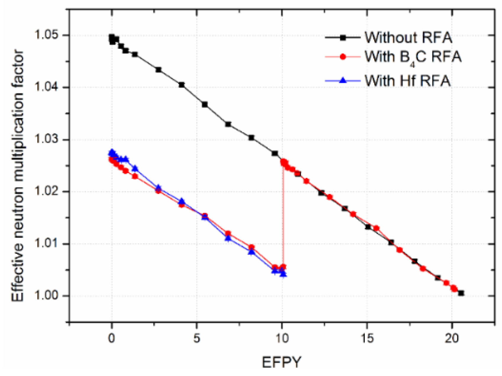
Figure 9 shows the core depletion results with and without the RFA module for a 15.5
w/
o enriched U
15N fuel. In the Serpent Monte Carlo depletion, the absorber material of RFA has been also depleted just like the fuel. From
Figure 9, it is clear that the maximum excess reactivity can be largely reduced by the RFA. With the B
4C and Hf absorbers, the initial excess reactivity are now about 2,559 pcm and 2,679 pcm, respectively, which are about half of the original one in
Figure 7, and the excess reactivity is about 500 pcm at 10 EFPYs. Now, the unburned RFA is removed from the core after 10-year operation, and the resulting reactivity is increased again to about 2,521 pcm and the MMR core can be operated over the next 10 EFPYs. It is important to note in
Figure 9 that reactivity of the second core after RFA removal is almost the same as in the original core without any RFAs. Although the Hf RFA core was analyzed only for the first 10 EFPYs, it is clearly expected that the reactivity behavior over the second 10 EFPYs will be very similar to the original and the B
4C-loaded case.
Figure 9.
Depletion results for the MMR core with and without RFA material.
Figure 9.
Depletion results for the MMR core with and without RFA material.
Therefore, it is clear that, by adopting the RFA concept, the excess reactivity can be reduced by about 50% and the target core lifetime of 20 EFPYs can be still achieved. In this work, the core before removal of the RFA is called first-half cycle and after the removal of the RFA is called second-half cycle. It is assumed that the RFA can be removed during a scheduled maintenance period of 30 days after the first-half cycle. The maximum excess reactivity of the MMR core can surely be reduced further by installing RFA with a bigger worth and shorter lifetime. For example, if an RFA is replaced every 5 years, the excess reactivity can be as small as ~1300 pcm during the 20-EFPY operation of the MMR.
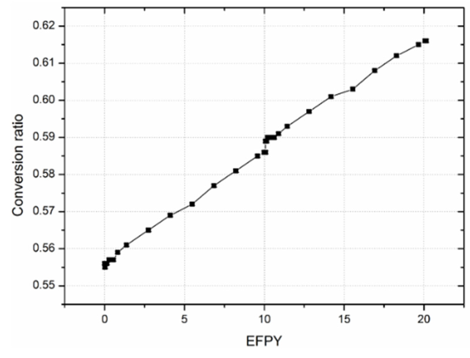
Figure 10 shows the conversion ratio of the KAIST MMR during the 20-year continuous operation. The conversion ratio is defined as the ratio of the number of fissile nuclides produced to the number of fissile nuclides consumed in the core. One notes that the conversion ratio is quite small and it increases from 0.56 to 0.62 gradually with burnup of the nitride fuel. The low conversion ratio of the compact MMR is due to high neutron leakage. The clear increasing tendency of the conversion ratio is ascribed to the initial LEU loading and Pu-239 is gradually bred with burnup. Since the Pu-239 has a higher η value than the initial fissile U-235, the neutron economy can increase with increasing inventory of Pu-239 in the core. It is worthwhile to note that the conversion ratio is suddenly increased right after removal of the RFA at the end of the first-half cycle. The discontinuous increase of the conversion ratio is because the neutron leakage is slightly reduced due to the slightly center-skewed radial power distribution after the RFA removal from the core.
Figure 10.
Conversion ratio of the KAIST MMR core.
Figure 10.
Conversion ratio of the KAIST MMR core.
Figure 11 shows the radial power profiles at BOL (beginning of life) and MOL1 (middle of life 1) for the first-half cycle and of MOL2 (middle of life 2) and EOL (end of life) for the second-half cycle.
Figure 11.
Normalized radial power distributions of the MMR core. (a) Beginning of life (BOL) and middle of life 1 (MOL1) of the first-half cycle core; (b) middle of life 2 (MOL2) and end of life (EOL) of the second-half cycle core.
Figure 11.
Normalized radial power distributions of the MMR core. (a) Beginning of life (BOL) and middle of life 1 (MOL1) of the first-half cycle core; (b) middle of life 2 (MOL2) and end of life (EOL) of the second-half cycle core.
Note that MOL1 and MOL2 indicate the end of operation of the first-half cycle and beginning of operation of the second-half cycle, respectively, and their power distributions should be different due to the RFA. For the first-half cycle core, the radial power peaking factors at BOL and MOL1 are 1.14 and 1.14, respectively, while they are 1.18 and 1.17 at MOL2 and EOL due to the removal of the RFA. It is clearly observed that removal of the RFA results in a slightly center-skewed radial power distribution at the MOL2 condition. In the first-half cycle, the radial power is relatively flat because of the insertion of the RFA.
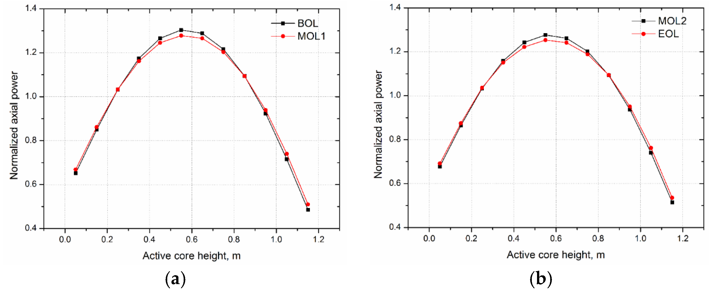
Figure 12 shows the normalized axial power distributions at BOL and MOL1 for the first and at MOL2 and EOL for the second-half cycle cores. It is clear that the axial power profiles are hardly affected by the RFA removal and they are rather similar throughout the whole operational period of the MMR. The axial power peaking at BOL, MOL1, MOL2, and EOL is 1.31, 1.28, 1.28, and 1.26, respectively. The stochastic uncertainty of the normalized powers is less than 1%.
Figure 12.
Normalized axial power distributions of the MMR core. (a) BOL and MOL1 of the first-half cycle core; (b) MOL2 and EOL of the second-half cycle core.
Figure 12.
Normalized axial power distributions of the MMR core. (a) BOL and MOL1 of the first-half cycle core; (b) MOL2 and EOL of the second-half cycle core.
Based on the radial and axial power peaking factors, a conservative 3-D power peaking factor (
Fq) can be calculated by Equation (1), where
PFradial and
PFaxial are radial and axial power peaking, respectively.
Table 4 tabulates the power peaking factors and calculated 3-D power peaking factor for several burnup conditions. The maximum 3-D power peaking factor is about 1.50 in the MMR core:
Table 4.
Power peaking factors of KAIST MMR core.
Table 4.
Power peaking factors of KAIST MMR core.
| Peaking Factor | First-Half Cycle | Second-Half Cycle |
|---|
| BOL | MOL1 | MOL2 | EOL |
|---|
| Radial | 1.139 | 1.138 | 1.177 | 1.169 |
| Axial | 1.308 | 1.283 | 1.278 | 1.258 |
| Fq | 1.490 | 1.461 | 1.503 | 1.470 |
Table 5 shows the primary control drum worth, stuck drum worth, secondary control rod worth and total worth of the KAIST MMR. For the “Primary-1” worth of the primary control system, it is assumed that the most-reactive drum is not operable. One notes that the primary control drum worth and secondary control rod worth are much higher than the maximum excess reactivity of ~2500 pcm in the core.
Table 5.
Worth the reactivity control system of the MMR core.
Table 5.
Worth the reactivity control system of the MMR core.
| Parameter | BOL (pcm) | MOL1 (pcm) |
| First-half cycle | Primary | 5,100 ± 46 | 5,087 ± 49 |
| Primary-1 | 4,616 ± 46 | 4,653 ± 48 |
| Secondary | 5,343 ± 46 | 5,587 ± 51 |
| Total | 11,418 ± 51 | 11,716 ± 55 |
| Parameter | MOL2 (pcm) | EOL (pcm) |
| Second-half cycle | Primary | 4,714 ± 47 | 4,614 ± 52 |
| Primary-1 | 4,329 ± 47 | 4,366 ± 50 |
| Secondary | 6,836 ± 48 | 6,878 ± 53 |
| Total | 12,851 ± 53 | 12,828 ± 60 |
Table 6 shows the burnup-dependent FTC and CVR of the KAIST MMR core. In this work, approximate FTC was calculated by Equation (2) for the several discrete temperatures, which are 700 K, 975 K, 1,200 K, and 1,400 K. Consequently, the FTC values are determined for three temperatures (838 K, 1,088 K, and 1,300 K) of the UN fuel. The CVR was calculated with Equation (4), in which ρ
normal is the reactivity at normal condition and ρ
void is calculated by removing all the coolant in the whole core.
Table 6.
Fuel temperature coefficient (FTC) and coolant void reactivity (CVR) of the MMR core.
Table 6.
Fuel temperature coefficient (FTC) and coolant void reactivity (CVR) of the MMR core.
| Parameter | BOL | MOL1 |
| First-half cycle | FTC (pcm/K) | 838 K | −0.40 ± 0.05 | −0.45 ± 0.06 |
| 1,088 K | −0.29 ± 0.06 | −0.35 ± 0.07 |
| 1,300 K | −0.28 ± 0.07 | −0.27 ± 0.07 |
| CVR (pcm) | −351 ± 14 | −33.8 ± 14.1 |
| Parameter | MOL2 | EOL |
| Second-half cycle | FTC (pcm/K) | 838 K | −0.48 ± 0.05 | −0.52 ± 0.04 |
| 1,088 K | −0.35 ± 0.06 | −0.28 ± 0.05 |
| 1,300 K | −0.29 ± 0.07 | −0.26 ± 0.07 |
| CVR (pcm) | −492 ± 14 | −1.47 ± 7.5 |
The FTC of the MMR core was calculated at BOL, MOL1, MOL2 and EOL conditions. It is clearly noted that the FTC is rather strongly negative and the CVR values are also clearly negative throughout the operation in the SCO
2-cooled MMR core. One also note that the FTC becomes less negative with temperature, as usual. It is mentioned that due to the statistical uncertainty of the Monte Carlo evaluation of the FTC, MOL1 has a slightly less negative FTC than MOL2. It is noteworthy that the CVR becomes less negative with burnup and it is quite small at the EOL condition of the core. The less negative CVR at higher burnup is due to the accumulation of Pu-239 with burnup. It is also noteworthy that the CVR value is more negative at the MOL2 condition than at MOL1, although the two cores have essentially the same fuel compositions. This is mainly due to higher axial neutron leakage through the central empty hole when the power profile is slightly more center-skewed with the removal of the RFA at MOL2. A consistent CVR trend is also noticed at the BOL condition, where it is reduced from − 350 ± 14 pcm to − 582 ± 13 pcm when the RFA is removed:
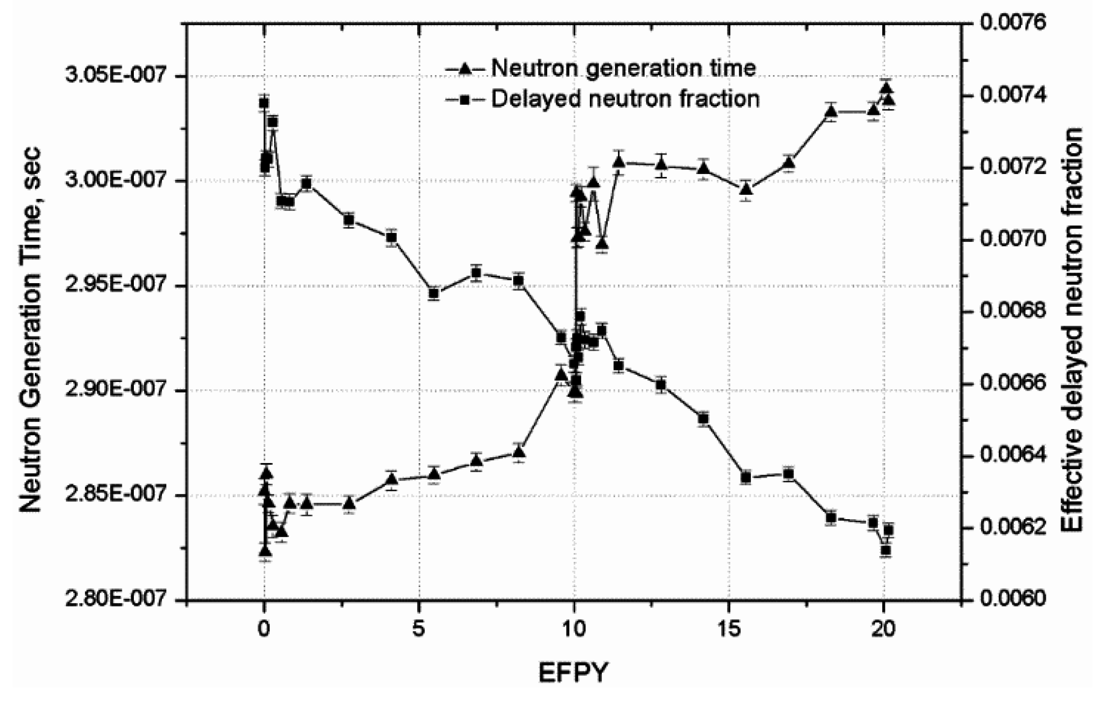
The kinetic parameters of the MMR core have been evaluated by the Serpent code and they are given as a function of EFPY in
Figure 13. It is noted that the effective delayed neutron fraction keeps decreasing with burnup and the neutron generation becomes longer as the fuel burnup increases. This behavior of the kinetic parameters can be easily understood by recalling that U-235 is decreasing with burnup and Pu-239 is gradually increasing with burnup. In addition, the net inventory of the fissile isotopes in the core is decreasing with burnup, leading to longer neutron generation time. It is worthwhile to note that the neutron generation time is suddenly increased right after the RFA removal.
Figure 13.
Kinetic parameters of the MMR core.
Figure 13.
Kinetic parameters of the MMR core.
4. Thermal-Hydraulic Analysis of Korea Advanced Institute of Science and Technology Micro Modular Reactor
This section presents a preliminary thermal-hydraulic analysis of the hottest channel in the KAIST MMR core. The analysis was performed with an assumption that heat is transferred radially from the outer surface of cladding to bulk coolant via convection. The bulk coolant mass flux is first approximated by using the Novendstern’s correlation for pressure drop balance model with wire wrap [
22], as shown in Equations (4)–(6), where
P is pitch,
D is fuel diameter,
L is fuel length,
f is friction factor for smooth pipe,
M is ratio between smooth tube and wire wrap structure,
H is wire-wrap lead length,
Re is Reynolds number, and
De is equivalent diameter.
With the aforementioned bulk coolant mass flux, convective heat transfer between the coolant and cladding surface is modeled using the Gnielinski’s correlations [
23] as shown in Equations (7), where
Nu is Nusselt number,
Pr is Prandtl number,
Lh is length from onset of heating,
Tbulk is coolant temperature,
Twall is cladding surface temperature, and
h is convective heat transfer coefficient.
Temperatures at the inner cladding wall and fuel outer surface are subsequently determined by using simple thermal conduction equations, in which gap conductance is approximated by Equations (9) and (10), where
hgap,open is conductance for an open gap,
kgas is thermal conductivity of gas, δ
eff is effective gap thickness,
tgap is thickness of gap, σ is Stefan-Boltzman constant,
rfuel is fuel radius, ε
f, ε
c are emissivity of fuel and cladding,
Tfo is fuel surface temperature, and
Tci is cladding inner surface temperature. All thermal properties of the component are evaluated at the average temperature of the two conducting surfaces: thermal conductivity of the cladding is estimated at the average temperature between inner and outer cladding surface temperatures, and helium properties are determined at average temperature between the fuel surface and cladding inner surface.
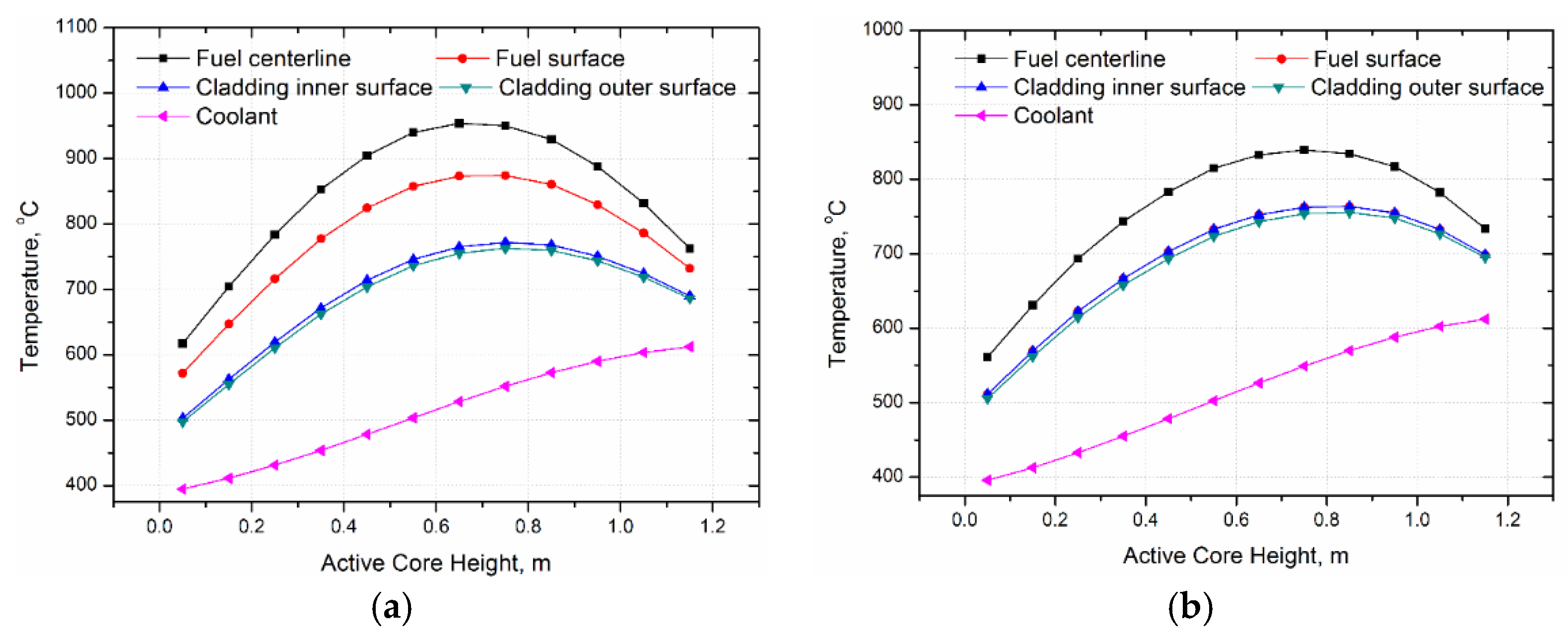
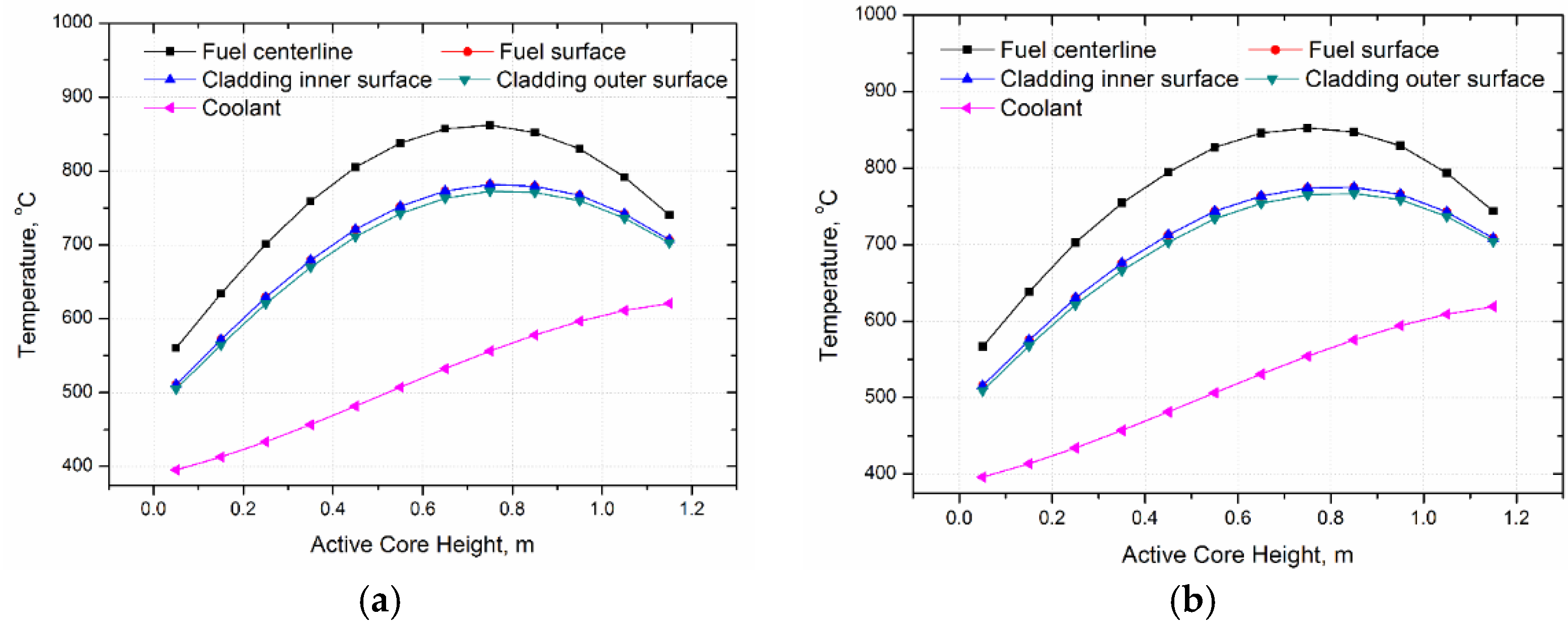
All of the above equations result in
Figure 14 and
Figure 15, which clearly show hot-channel temperature distributions at BOL, MOL1, MOL2, and EOL conditions of the MMR core. Meanwhile,
Table 7 contains the maximum temperatures of fuel and cladding. One notes that fuel centerline temperature at the hot channel is far below the fuel melting point of 3078 K over the whole 20-EFPY period. However,
Table 7 indicates that the peak cladding temperature is quite close to the design limit of 800 °C [
4]. It may be possible to reduce the cladding peak temperature though an orificing of the coolant flow. In this thermal analysis, it was assumed that the gap between fuel and cladding is open at the BOL condition only and it disappears at MOL1, MOL2 and EOL due to the swelling of the UN fuel. Actually, it is assumed that the fuel is fully contacting the cladding and the temperature is continuous across the interface. Consequently, one notes that in
Figure 14 and
Figure 15 the fuel surface temperature is identical to that of the cladding inner surface. Of course, in the actual situation, there should be some temperature drop across the closed gap due to incomplete surface contact. It is expected that the temperature drop across the closed gap should be much smaller than ~100 °C, temperature drop in the open gap.
Table 7.
Maximum material temperature of the hottest channel at several burnups.
Table 7.
Maximum material temperature of the hottest channel at several burnups.
| Burnup Point | Fuel Centerline (°C) | Fuel Surface (°C) | Cladding Inner Surface (°C) |
|---|
| BOL | 954.0 | 873.5 | 771.9 |
| MOL1 | 839.3 | 763.6 | 763.6 |
| MOL2 | 861.9 | 781.9 | 781.9 |
| EOL | 852.6 | 775.0 | 775.0 |
Figure 14.
Hot channel temperature distributions of first-half cycle MMR. (a) BOL of the first-half cycle core; and (b) MOL1 of the first-half cycle core.
Figure 14.
Hot channel temperature distributions of first-half cycle MMR. (a) BOL of the first-half cycle core; and (b) MOL1 of the first-half cycle core.
Figure 15.
Hot channel temperature distribution of second-half cycle MMR. (a) MOL2 of the second-half cycle core; and (b) EOL of the second-half cycle core.
Figure 15.
Hot channel temperature distribution of second-half cycle MMR. (a) MOL2 of the second-half cycle core; and (b) EOL of the second-half cycle core.


