1. Introduction
Recently, with the pressure of energy shortages and environmental pollution, large capacity lithium ion batteries with have been developed for use in hybrid electric and electric vehicles. However, their heat generation is difficult to dissipate during the charging and discharging processes, and this could lead to fires or explosions.
Several previous studies have been conducted on the thermal safety of lithium ion batteries, mostly focused statically on the thermal stability of the materials [
1,
2,
3] and flame retardant additives [
4,
5,
6]. However, most fires and explosions involving lithium ion batteries have occurred during operation, especially during the process of high current rate charge and discharge. Therefore, research on the temperature changes of lithium ion batteries during operation is an important way of predicting the potential fire risk. Mathematical simulation based on a transient and thermal-electrochemical coupled model is an effective tool to obtain fundamental ideas on how the heat is generated and transferred out of a battery. Bernardi
et al. [
1] developed a heat-generation model for battery systems including the contributions from electrochemical reactions, mixing enthalpies and phase changes. Guo
et al. [
7] developed a three-dimensional thermal model and simulated it using a finite element method. Kim
et al. [
8] constructed a three-dimensional thermal abuse model based on the chemical reactions. He
et al. [
9] used a high-fidelity two dimensional computational fluid dynamics model to study the thermal management of a Li-ion battery module. Wang
et al. [
10] investigated the optimal structure and thermal management of the battery module by a three-dimensional computational fluid dynamics method and lumped model. In this work, the heat of the battery materials measured by a C80 micro- calorimeter was embedded into the traditional thermal model to predict thermal runaway, and furthermore, to explore the effect of overheated cells on adjacent batteries in the battery module.
2. Modelling
Lithium titanate battery cells have three primary functional components,
i.e., the anode lithium titanate material, electrolyte, and the cathode lithium nickel-cobalt-manganese-oxide materials. During charging, lithium ions deintercalate from the positive electrode and intercalate into the negative electrode, and the reverse takes place during discharging. During battery charging/discharging, various chemical and electrochemical reactions as well as transport processes take place, and the internal system follows the charge conservation, lithium ion diffusion, Butler-Volmer law [
1,
7,
8,
11,
12] in the one-dimensional cell model, which is used to model the Li-ion battery chemistry, while a three-dimensional and lumped model is used to model the temperature in the battery.
In a lithium ion battery, the liquid electrolytes tend to show limited mobility, so the contribution of convection to heat transfer inside the battery can be neglected. In addition, the radiative heat transfer of different components is insignificant. Therefore, the main mechanism inside a battery is the conductive heat transfer and the corresponding heat transfer equation is:
where ρ is the density, kg/m
3,
Cp is the specific heat capacity, kJ/(kg·K),
KT is the thermal conductivity, W/(m·K),
Qg is the heat generation inside the battery,
Qex is a boundary condition, it is the sum of the convective and radiative heat transfers on the surface. The convection at the boundary according to Newton’s law of cooling is expressed as follows:
The radiative heat transfer at the boundary according to Stefan-Boltzmann law is expressed as follows:
The one-dimensional cell model and the three-dimensional thermal model are coupled by the generated heat source and the average temperature. The heat source based on the active battery domain is set to the average of the heat generated in the cell model using a model coupling integration variable. In the real thermal runaway process of the battery module, there are some inner short circuits that result in some hotspots, that is, the heat generation rate is inhomogeneous [
13], but it is assumed homogenous for the single cell in the battery module for the easier implementation of the coupled method. Therefore, the temperature is set to the mean temperature in the battery and the thermal model uses an integrated model coupling.
When the temperature reaches a certain value, such as 80 °C [
14] a series of uncontrolled chemical reactions between the negative materials and electrolyte would be triggered, such as the electrodes’ reactions with the electrolyte, and electrode decomposition [
15,
16], releasing large amounts of material decomposition heat, that is
Qh. For lithium titanate cells, the material decomposition reaction is triggered at 177 °C according to the C80 microcalorimeter experiment, therefore, if the temperature inside the lithium titanate battery reaches 177 °C, the heat source of the thermal runaway model will be made up of three parts, namely the reversible heat, irreversible heat and decomposition heat, that is:
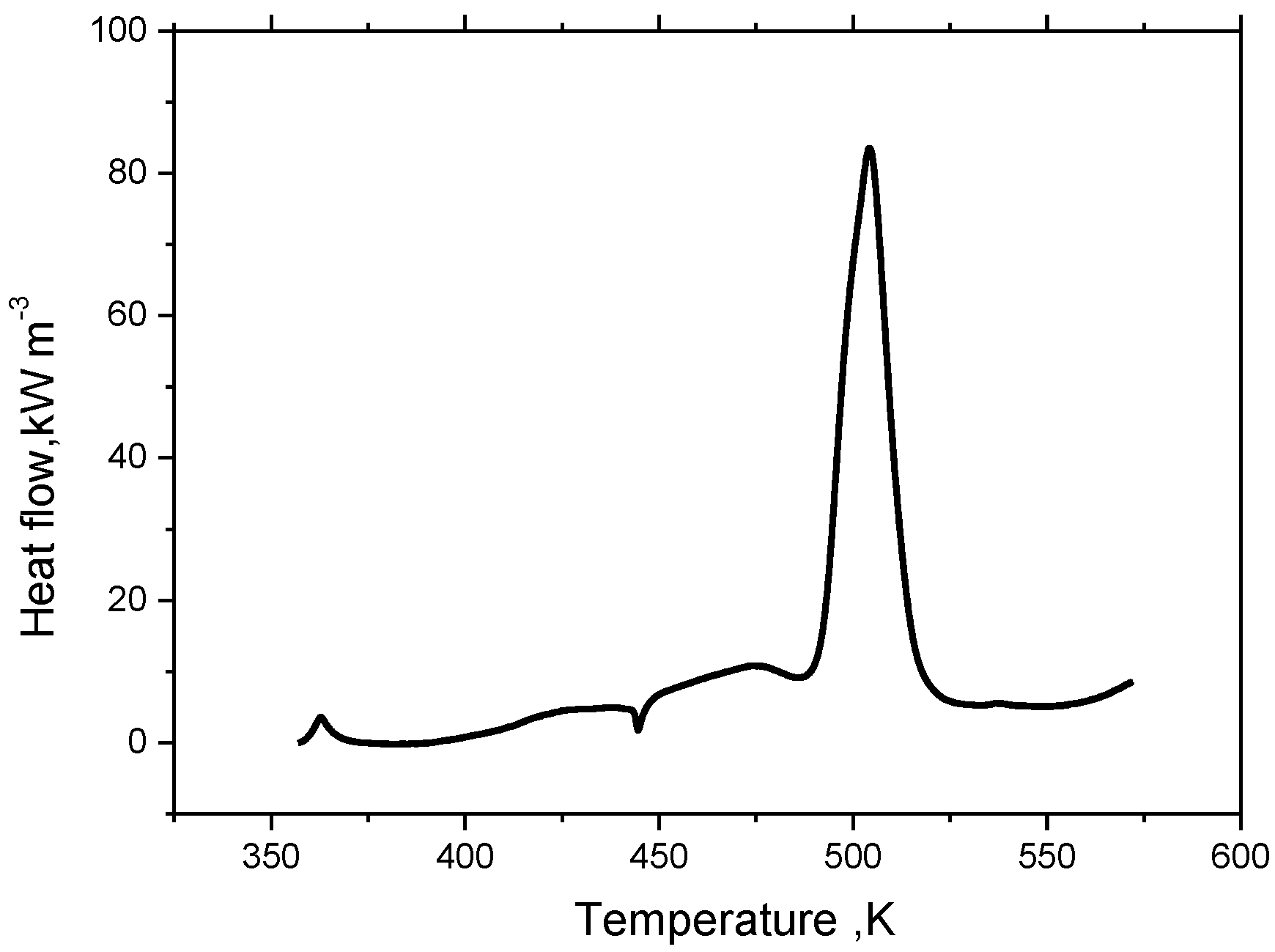
In Equation (4), the
Qh is measured by thermal analysis experiment. Based on C80 micro calorimeter experiments, the heat flow of a lithium ion titanate battery (electrolyte: 44.0 mg; Li
4Ti
5O
12 (LTO): 54.2 mg; LiNi
xCo
yMn
zO
2 (NCM): 57.0 mg; separator: 2.5 mg) can be obtained at elevated temperature. According to the linear relationship between the capacity and the heat generation, the heat flow of a 50 Ah lithium titanate battery is speculated to be as shown in
Figure 1.
Figure 1.
The heat flow curve of 50 Ah battery extracted from the C80 heat flow of a CR2032 cell.
Figure 1.
The heat flow curve of 50 Ah battery extracted from the C80 heat flow of a CR2032 cell.
The thermal abuse model was established considering the material decomposition heat under extreme conditions. On the basis of the electrochemical thermal abuse model, thermal runaway conditions could be simulated. The parameters used in the model are listed in
Table 1. In addition, the entropy changes of Li
4Ti
5O
12 electrode and LiNiCoMnO
2 were adopted from reference [
17].
Table 1.
Thermal and physical properties of each material used in the simulation [
18,
19,
20].
Table 1.
Thermal and physical properties of each material used in the simulation [18,19,20].
| Parameters | Al Foil | NCM | Electrolyte | LTO | Cu Foil |
|---|
| Electric conductivity, S/m | 3.774 × 10⁷ | 100 | 8.5 | 100 | 5.988 × 10⁷ |
| Diffusion coefficient of lithium ion, m2/s | – | 2.5 × 10⁻¹⁶ | 3 × 10⁻¹ | 6.8 × 10⁻¹⁵ | – |
| Radius of the spherical particle, μm | – | 0.01075 | – | 1.2 | – |
| Volume fraction | – | 0.39 | – | 0.25 | – |
| Electrochemical reaction rate constant, m/s | – | 2 × 10⁻¹² | – | 3 × 10⁻¹³ | – |
| Thermal conductivity, W/(m·K) | 238 | 5 | 0.344 | 1.04 | 398 |
| Density, kg/m3 | 2702 | 1500 | 1008.98 | 3510 | 8933 |
| Heat capacity, J/(kg·K) | 903 | 700 | 1978.16 | 1437.4 | 385 |
3. Results and Discussion
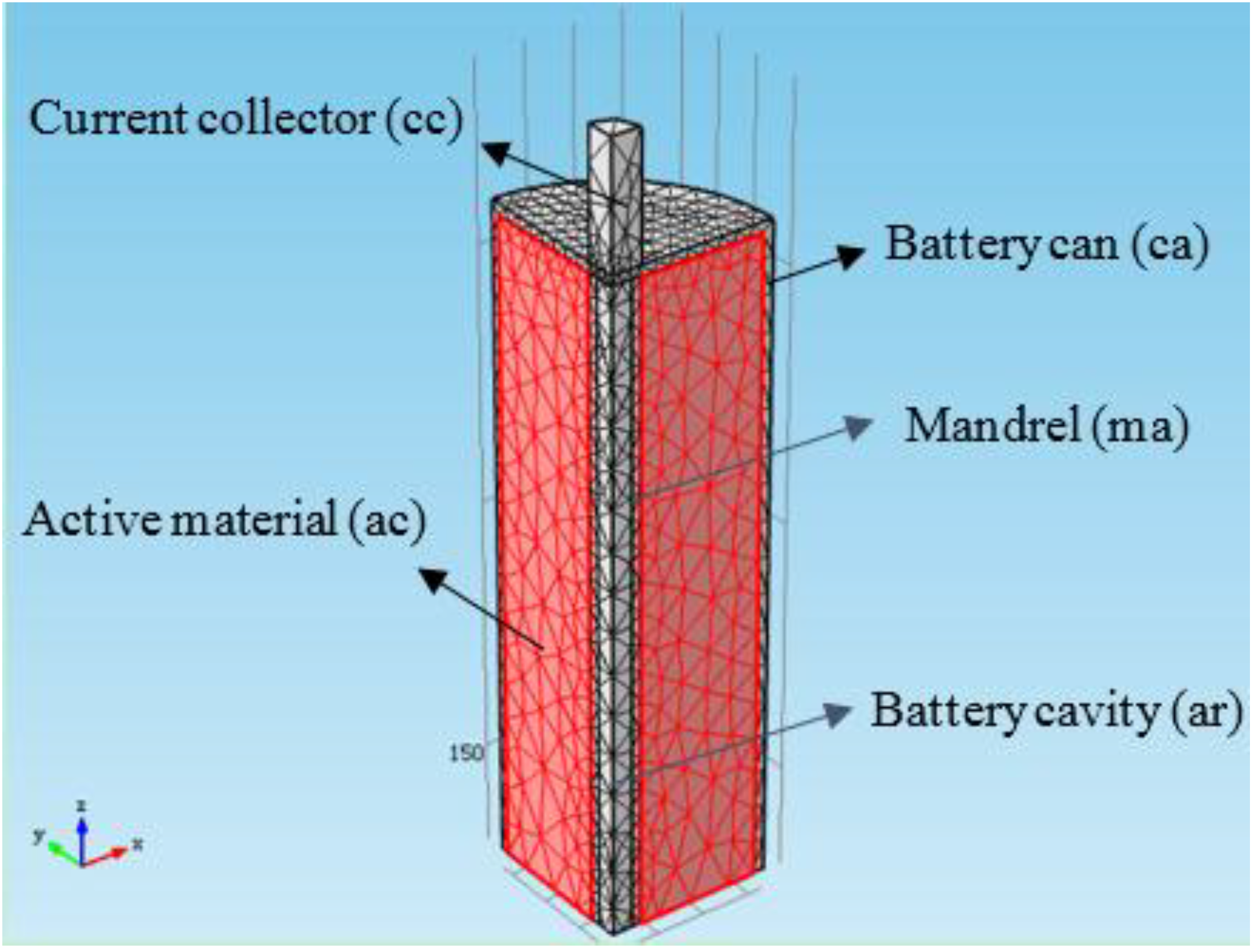
In the simulation, a 50 Ah lithium titanate battery (66 ± 0.5 mm in diameter, 260 ± 1 mm in height) was selected as the research object and 1/8th of the battery were simulated according to the geometric symmetry, as shown in
Figure 2. There are 421 edge elements and six vertex elements in the 1D electrochemical model. There are 5918 tetrahedral elements, 2525 triangular elements, 334 edge elements, and 24 vertex elements in the 3D thermal analysis. The method of calculation is similar to that reported in our previous work [
21].
Figure 2.
The 1/8 part geometric model used for the simulation.
Figure 2.
The 1/8 part geometric model used for the simulation.
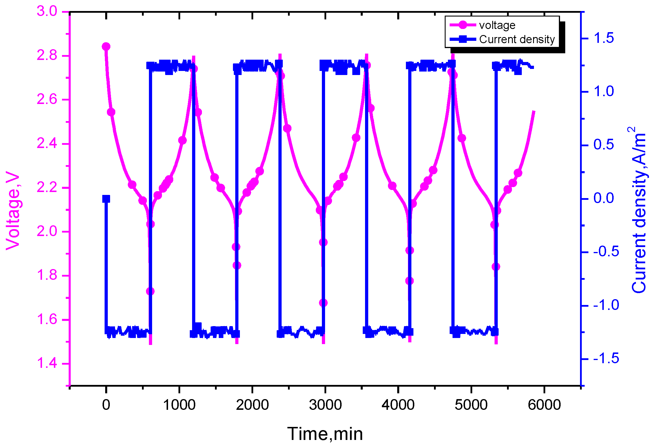
In the simulation, the battery was discharged down to 1.5 V with discharge rates of 0.1 C, 0.5 C, 1 C and 1.5 C, then charged to 2.8 V with the same current, as shown in
Figure 3. During this cycling operation, the current rate 0.5 C is the current value of 25 A, which corresponds to a current density of 6.21 A/m
2.
Figure 3.
The profile of voltage and current density at 0.1 C cycling.
Figure 3.
The profile of voltage and current density at 0.1 C cycling.
3.1. Cycling Rate Effect on the Cell Thermal Response
As shown in
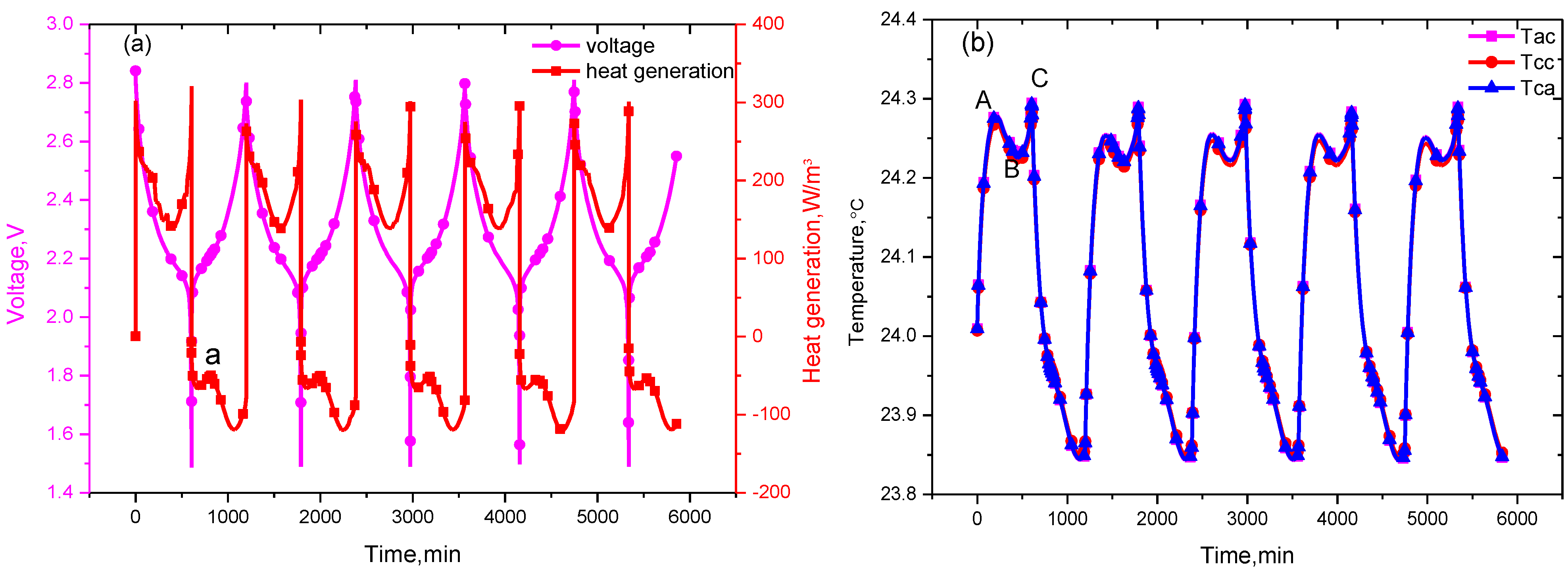
Figure 4a,b, the heat generated by the electrochemical reactions, ohm internal resistance and polarization changes nonlinearly during the discharge process. The heat generation increases sharply during the early discharge stage, then decreases as overpotentials diminished, and increases again at the end. This causes the temperature in the cell to correspondingly rise sharply at the beginning of discharge, then decline, and increase again. That’s the reason why two peaks (designated as A and C) and one valley (designated as B) exist in the temperature curve during the discharge process. In addition, due to the heat accumulation, the temperature value of the second peak is higher than the first one, that is the temperature peaks are ordered as C > A > B, in which point A is 24.28 °C, point B is 24.23 °C, and point C is 24.20 °C.
Figure 4.
Figure 4. The profile of (a) voltage and heat sources; and (b) the temperature variation curve at 0.1 C cycling.
Figure 4.
Figure 4. The profile of (a) voltage and heat sources; and (b) the temperature variation curve at 0.1 C cycling.
During the charging process, the heat of absorption curve does not show consistent trends. There are two valleys and one peak on the curve. For the 0.1 C current rate, the reversible heat generation plays a dominant role in the heat generation [
22]. The charging reactions for lithium ion secondary batteries are endothermic processes [
23], therefore, the irreversible heat generation composed of Joule heat and polarization heat is less than the reversible heat value, causing cells to absorb heat from the environment. With the existence of an endothermic peak, the temperature in the charging process is lower than the ambient temperature. In the subsequent cycles, the temperature curve shows a similar trend. As shown in
Figure 4b, the curves of the battery internal temperature
Tac, the battery can temperature
Tca, and the current collector temperature
Tcc overlap, so the temperature difference between the battery inside and outside is small.
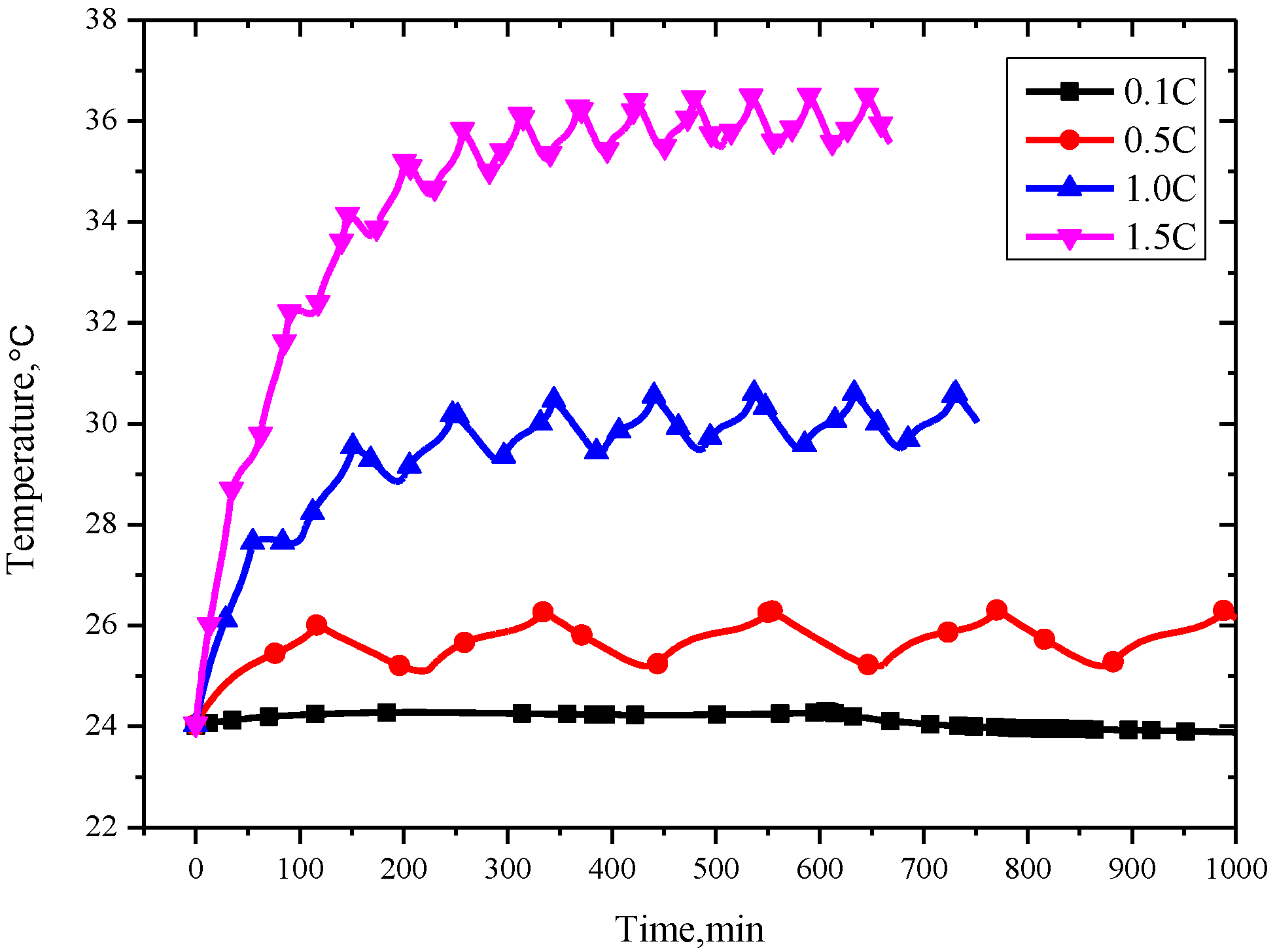
As expected, the temperature has a positive correlation with the charging/discharging current as shown in
Figure 5. The maximum temperatures during cycling at 0.1 C, 0.5 C, 1.0 C and 1.5 C are 24.28 °C, 26.29 °C, 30.53 °C and 36.43 °C, respectively. This is because the reversible heat production is proportional to the current rate.
Figure 5.
The temperature change under current rates of 0.1, 0.5, 1.0 and 1.5 C cycling.
Figure 5.
The temperature change under current rates of 0.1, 0.5, 1.0 and 1.5 C cycling.
In addition, the time to reach thermal balance for cycling rates of 0.1 C, 0.5 C, 1.0 C and 1.5 C are 77 min, 334.2 min, 441.9 min, and 478.69 min, respectively, as shown in
Figure 5. On the whole, the battery temperature could reach equilibrium with the ambient temperature under different charge and discharge rates. The higher the current rate, the longer the times needed to reach balance, and the bigger the amplitude of the thermal equilibrium temperature. The range of the temperature fluctuation in the cell is 0.45 °C, 1.0 °C, 1.2 °C, and 1.5 °C, and the cycle times to achieve thermal balance are increasing with the current rate increase from 0.1 C to 1.5 C, respectively.
3.2. Cell Thermal Runaway Simulation
When the battery cycles with the natural convection boundary conditions, the temperature inside the cell reaches thermal balance with the outside environment as discussed above. Hoverer, for the battery operating in an adiabatic environment, no heat exchanges exist between the battery and the environment, so whether the thermal balance was reached or not was intensively investigated.
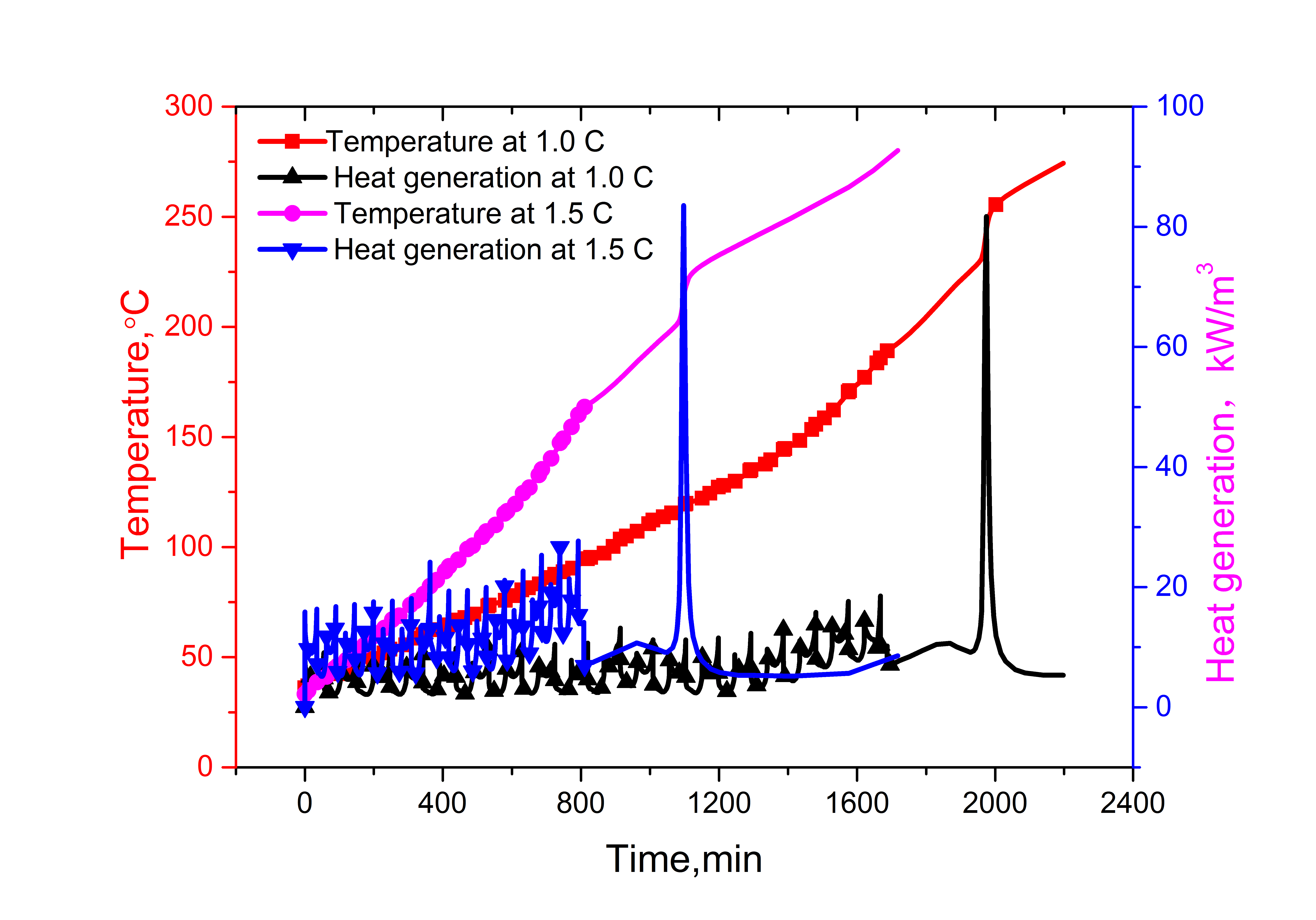
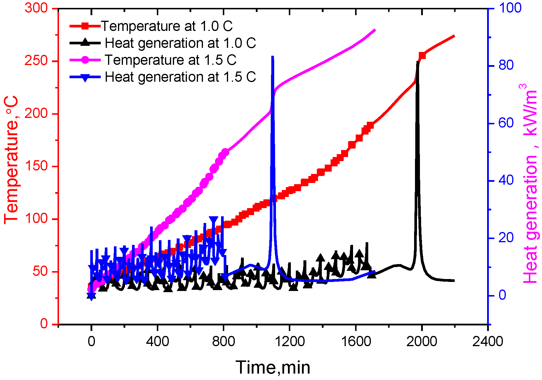
It can be seen from the
Figure 6 that the battery temperatures increase gradually with the increase of cycling times under adiabatic conditions. When the battery internal temperature reached the separator pyrolysis temperature, a series of exothermic reactions will go out of control. Furthermore, the reaction rate increases due to an increase in temperature causing a further increase in temperature and hence a further increase in the reaction rate [
24]. With the heat accumulated, the melting down temperature of the polymer separator is reached, which is 177 °C for a lithium ion titanate battery, an internal short circuit happens, the heat generation increases sharply, and correspondingly a sharp increase in the battery internal temperature is seen, resulting in the thermal runaway.
Figure 6.
The temperature and heat resource changes under adiabatic conditions at the current rates of 1.0 C and 1.5 C, respectively.
Figure 6.
The temperature and heat resource changes under adiabatic conditions at the current rates of 1.0 C and 1.5 C, respectively.
Due to the amount of heat related to the current rate, the heat generation at 1.5 C is higher than that of 1.0 C, and it is same for the temperature. Therefore, thermal runaway at 1.5 C occurs earlier than at 1.0 C. In the 17th charging process,
t = 90,200 s, the battery temperature reached 177 °C (
i.e., separator melt-down temperature) at 1.0 C, while the battery temperature of 1.5 C reached the separator melting temperature in the 16th charging process, that is 48,430 s, and then the temperature rose sharply, triggering thermal runaway. As shown in
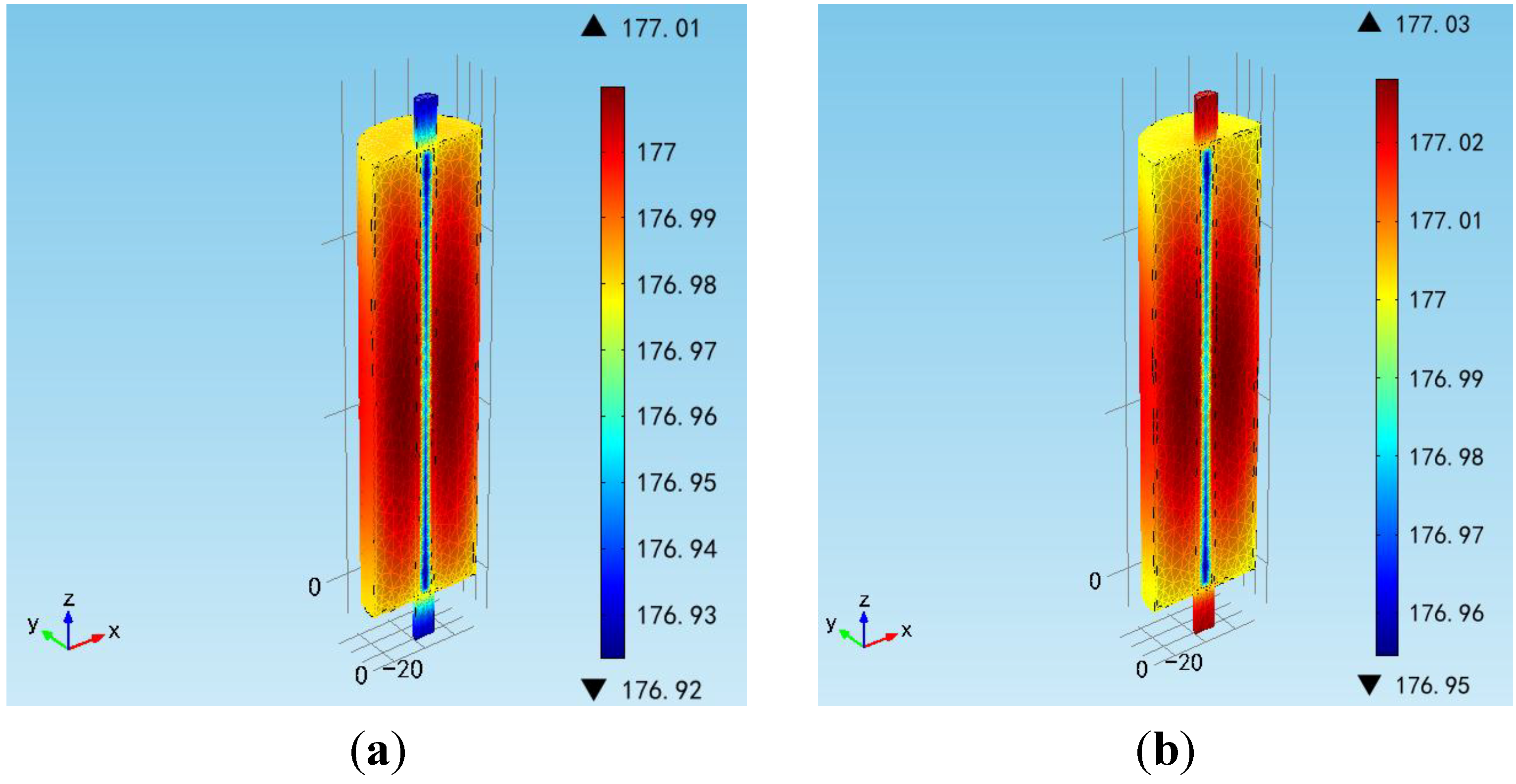
Figure 7, the maximum value of the battery internal temperature appears in the middle of the battery as thermal runaway occurs. Therefore, the bigger the current rate, the higher the potential risk of thermal runaway is.
Figure 7.
Temperature distribution at the moment of thermal runaway at (a) 1.0 C; and (b) 1.5 C cycling.
Figure 7.
Temperature distribution at the moment of thermal runaway at (a) 1.0 C; and (b) 1.5 C cycling.
3.3. Thermal Runaway Cell Effect on the Battery Module
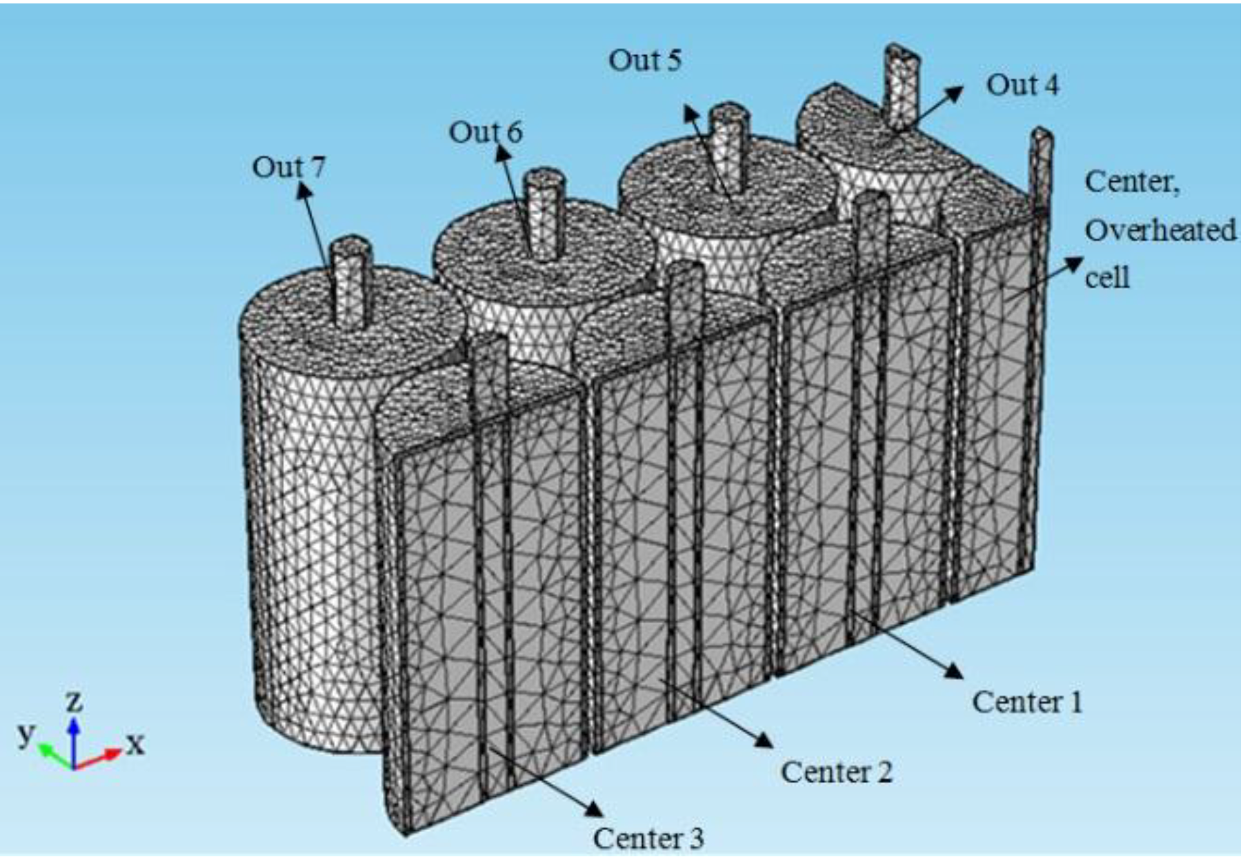
For a 7 × 3 battery module (three rows and seven cells in every row) as shown in
Figure 8, the effect of an overheated battery on the surrounding batteries was investigated. The middle cell (marked as Center) was select as the overheated cell, and its temperature rise plotted as shown in
Figure 9. There are 3 mm spaces between the cells instead of them being in direct contact with each other. The battery module thermal behavior was simulated under natural convection conditions.
Figure 8.
The geometric model of a battery module (1/8 parts) used for simulation.
Figure 8.
The geometric model of a battery module (1/8 parts) used for simulation.
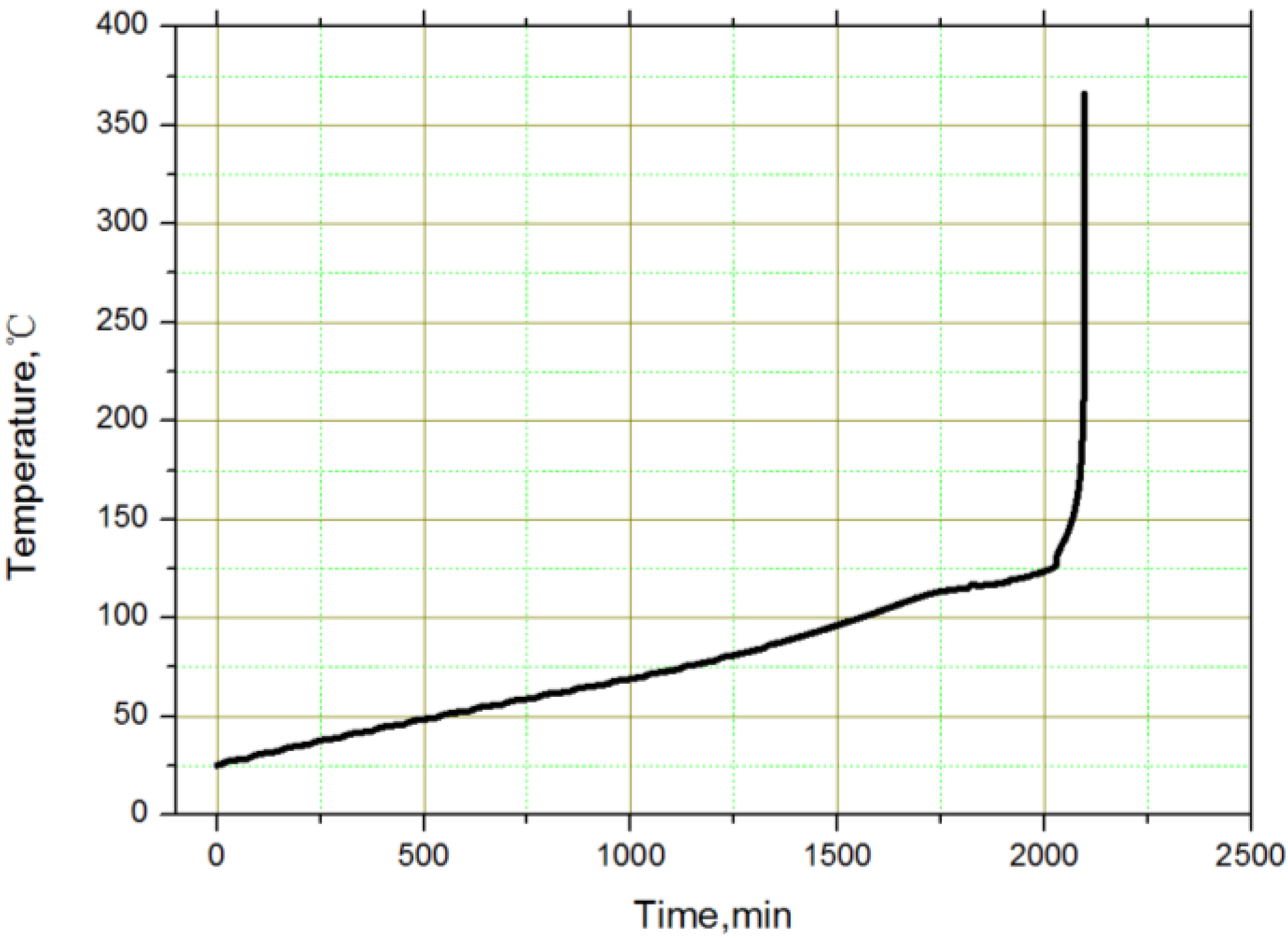
Figure 9.
The thermal load of the overheated battery in the middle of the module.
Figure 9.
The thermal load of the overheated battery in the middle of the module.
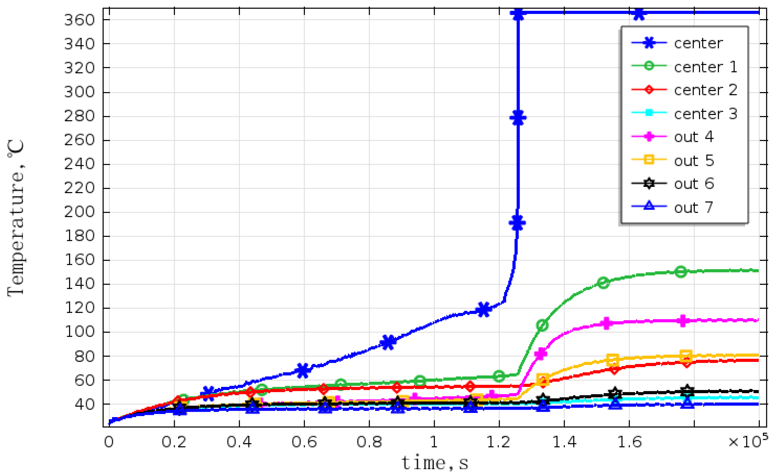
The temperatures of adjacent cells were obtained and the corresponding curves were as shown in
Figure 10. Because of the existence of thermal radiation and convection among the batteries, the temperature of the cell closest to the overheated one is higher than that of the others. This is because that radiation is related to the distance, and the influence decreases as the distance increases. The battery temperature is also influenced by the cooling conditions. Although the battery number Center 1 and Out 4 have the same distance to the overheated battery, Center 1 is located inside the battery module, so its cooling conditions are relatively poorer than that of Out 4, so its temperature is higher than that of Out 4. Out 7 is under the best cooling conditions, and has the largest distance from overheated cell, and therefore, its temperature is the lowest. In addition, the temperature of battery numbered Center 1 has exceeded 140 °C, and then the negative material decomposes and releases heat. As heat is accumulated and the temperature increases, the separator begins to melt and cause a thermal runaway, which will trigger a chain reaction in the battery module, in some cases causing the entire battery to ignite or rupture. This verified the conclusion speculated by Spotnitz
et al. [
24] that the thermal runaway of a single battery could lead the whole battery module to thermal runaway.
Figure 10.
The temperature curves of the battery module under natural convection.
Figure 10.
The temperature curves of the battery module under natural convection.
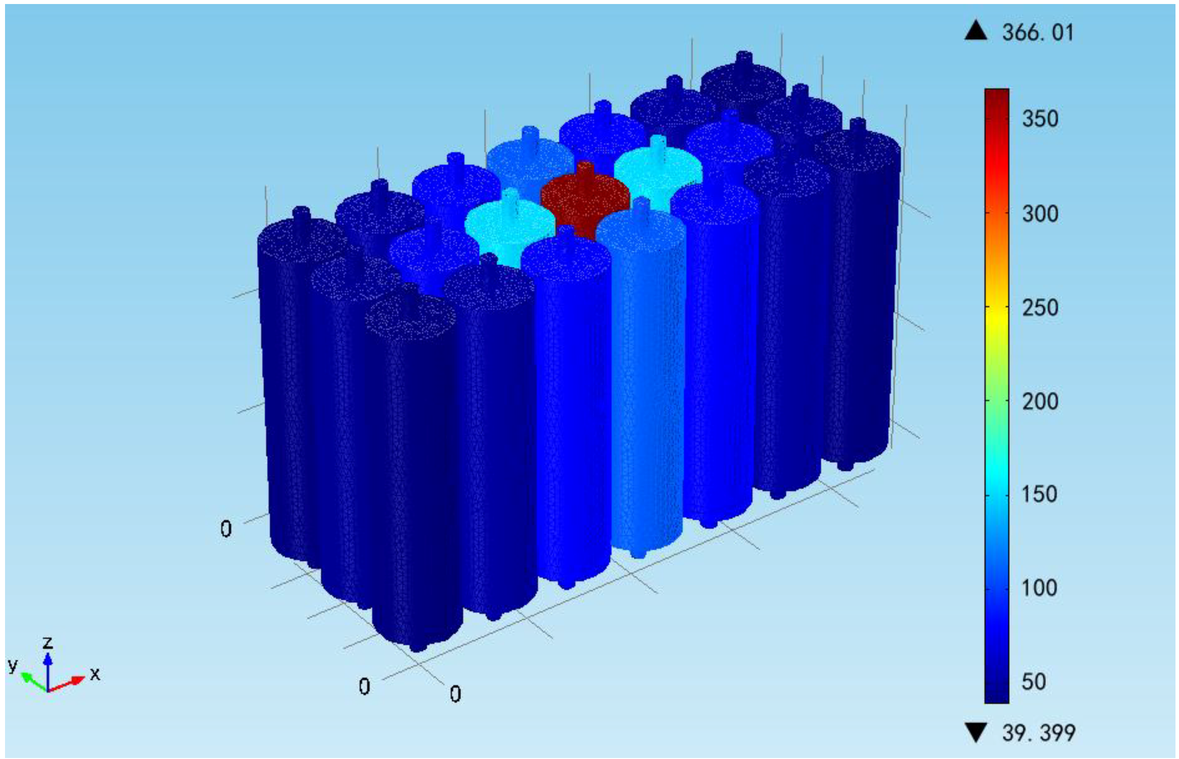
The temperature distribution of the battery module at the end of the simulation is shown in the
Figure 11. It can be seen that the battery temperature is decreasing with the increase of distance and the improved cooling conditions. The maximum and minimum temperatures in the module are 155 °C and 39.40 °C, respectively, except for the overheated one. The uniform temperature distribution in the module indicates that cooling conditions should be improved, especially the inside cooling conditions, to avoid any abnormal temperature points and ensure the safety of the module. It should be noted that it is assumed that the battery heat generation is homogeneous in the model. However, in a real thermal runaway case, the inner short circuit will cause a hotspot and then the thermal runaway propagates to the whole battery. Therefore, the inhomogeneous modelling method will be considered for more accurate numerical output in predicting the thermal runaway propagation for the battery module.
Figure 11.
Temperature distribution of the battery module (the units are °C).
Figure 11.
Temperature distribution of the battery module (the units are °C).
4. Conclusions
With the aid of the finite element technique, the thermal behavior of a 50 Ah lithium titanate battery and the thermal effect of an overheated cell on the surrounding cells in a 7 × 3 battery module are simulated. First, the greater the current rate, the higher the battery temperature and the longer the time required for thermal balance with the environment is. The simulation on an overheated battery in the 7 × 3 battery module shows that the temperatures of the overheated surrounding cells exceed 140 °C, which will cause the decomposition of the polymer separator, and then trigger the thermal runaway of the whole battery followed by a chain reaction in the module, leading to a potentially uncontrollable explosion. If the working current rate is 1.0 C, more attention should be paid to improve the battery cooling conditions, because the cell temperature in the center of the module could rise sharply under poor working conditions, which will cause the other adjacent cells’ temperature to rise, and thus increase the risk of thermal runaway.


