Performance Analysis of the Vehicle Diesel Engine-ORC Combined System Based on a Screw Expander


Abstract
: To achieve energy saving and emission reduction for vehicle diesel engines, the organic Rankine cycle (ORC) was employed to recover waste heat from vehicle diesel engines, R245fa was used as ORC working fluid, and the resulting vehicle diesel engine-ORC combined system was presented. The variation law of engine exhaust energy rate under various operating conditions was obtained, and the running performances of the screw expander were introduced. Based on thermodynamic models and theoretical calculations, the running performance of the vehicle diesel engine-ORC combined system was analyzed under various engine operating condition scenarios. Four evaluation indexes were defined: engine thermal efficiency increasing ratio (ETEIR), waste heat recovery efficiency (WHRE), brake specific fuel consumption (BSFC) of the combined system, and improvement ratio of BSFC (IRBSFC). Results showed that when the diesel engine speed is 2200 r/min and diesel engine torque is 1200 N·m, the power output of the combined system reaches its maximum of approximately 308.6 kW, which is 28.6 kW higher than that of the diesel engine. ETEIR, WHRE, and IRBSFC all reach their maxima at 10.25%, 9.90%, and 9.30%, respectively. Compared with that of the diesel engine, the BSFC of the combined system is obviously improved under various engine operating conditions.1. Introduction
Internal combustion (IC) engines consume a large amount of petroleum resources. The thermal efficiency of IC engines is less than 40%. A large proportion of the energy from fuel combustion is released in the form of waste heat into the atmosphere through the exhaust and the coolant system [1,2]. Waste heat recovery is an effective means to improve fuel consumption, save energy, and reduce IC engine emissions [3].
The organic Rankine cycle (ORC) system is considered effective in converting low-grade waste heat to useful work and has recently been widely studied and applied in many domains [4–7]. Wang et al. [8] established an off-design model of an ORC system driven by solar energy. El-Emam et al. [9] presented thermodynamic and economic analyses on a novel type of geothermal regenerative ORC system. Uris et al. [10] assessed the technical and economic feasibility of biomass-fueled ORC power plants. Carcasci et al. [11] indicated that the use of an ORC is a promising choice for the recovery of waste heat at low or medium temperatures.
Many researchers have concluded that the ORC system is a highly effective means of recovering waste heat for IC engines [12–15], thus the topic has become a research hot spot worldwide. Peris et al. [16] utilized the ORC system to recover the waste heat of jacket cooling water from IC engines. Meinel et al. [17] recovered the exhaust energy of IC engines by means of an ORC system. Hajabdollahi et al. [18] built a model of an ORC for diesel engine waste heat recovery and analyzed the thermal efficiency and the total annual cost of the system.
In an ORC system, the match of organic working fluids with heat source and systems significantly affects system performance. Numerous researchers have conducted studies on organic working fluid selection [19–22]. Wang et al. [23] analyzed nine different pure organic working fluids and indicated that R245fa and R245ca are the most suitable working fluids for engine waste heat recovery applications. Lakew et al. [24] concluded that R245fa can provide high power output for temperatures higher than 160 °C. Rayegan et al. [25] asserted that R245fa and R245ca are suitable working fluids for an ORC system at medium temperature. Based on the literature survey, R245fa performs suitably as the working fluid in an ORC system because of good thermodynamic and environmental performance.
As a key component of the ORC system, an expander is used to produce useful work, and the running performance of the expander has a crucial effect on the running performance of the ORC system, including such aspects as net power output (Ẇnet [26–30]. Kang et al. [31] conducted an ORC capable of generating electric power with a radial turbine and analyzed the influence factors of the ORC system. Twomey et al. [32] tested the performance of a scroll expander in a small ORC system. Qiu et al. [33] concluded that vane expanders and scroll expanders might be the best choices for micro-scale combined heat and power systems.
In practice, a vehicle IC engine generally runs under various operating conditions, and the amount of waste heat from IC engine varies with these engine operating conditions. To recover the waste heat efficiently and effectively under engine various operating conditions, it is crucial to know the variation law of engine exhaust energy and select an ideal expander. In this paper, by experiment, the variation law of engine exhaust energy rate under various operating conditions was obtained, and the running performances of the screw expander were investigated, then the vehicle diesel engine-ORC combined system was designed. Furthermore, by theoretical calculation, the running performances of the vehicle diesel engine-ORC combined system were analyzed under various operating conditions of the engine.
As we all know, there are many electrical equipments powered by the electricity generator and battery in the vehicle. Generally, the electricity generator is driven by the vehicle engine, which certainly decreases the net power output of the vehicle engine. In this research, an ORC system is adopted to recover waste heat from diesel engine exhaust, and the screw expander used in the ORC system, in place of vehicle engine, is employed to drive the electricity generator. In this way, we can effectively improve the fuel consumption of the vehicle engine. Furthermore, electricity generation based on waste heat recovery of vehicle engine may also be an efficient way of saving energy and reducing emissions for the internal combustion engine–electric motor hybrid vehicle in the near future.
2. Experimental Study on Exhaust Energy Rate and Screw Expander
2.1. Available Exhaust Energy Rate of Vehicle Diesel Engine
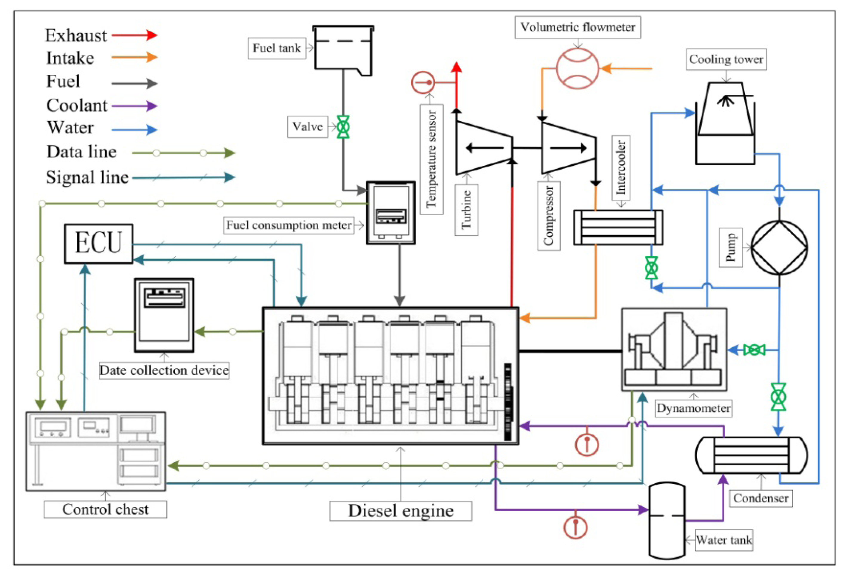
The IC engine used for the study of waste heat recovery is a six-cylinder and four-stroke vehicle diesel engine. The main parameters of the vehicle diesel engine are listed in Table 1. The diesel engine experimental system is illustrated in Figure 1. The test was performed under engine various operating conditions, including more than 85 operating condition points. During the diesel engine test, the engine speed varied from 600 r/min to 2200 r/min, and the engine torque varied from 0 N·m to 1500 N·m. Some of the tested operating condition points are listed in Table 2.
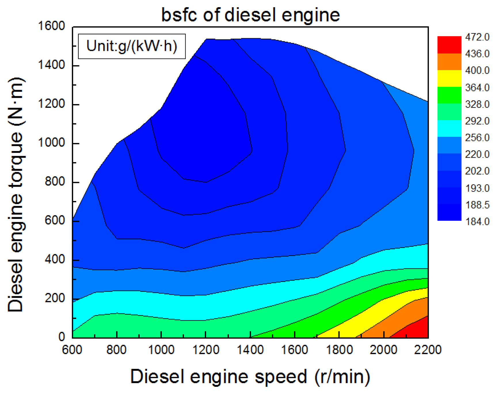
The variation trend of brake specific fuel consumption (BSFC) of the diesel engine under various operating conditions is shown in Figure 2. When the engine speed is lower than 1100 r/min, BSFC gradually decreases with the increase of engine torque. When the engine speed is higher than 1100 r/min, BSFC gradually decreases initially and then gradually increases with the increase of engine torque. When the engine torque is lower than 400 N·m, BSFC gradually decreases initially and then gradually increases with the increase of engine speed. When the engine runs with high speed and low torque, BSFC is relatively high. When engine speed is 1100 r/min and engine torque is 1300 N·m, BSFC reaches its minimum.
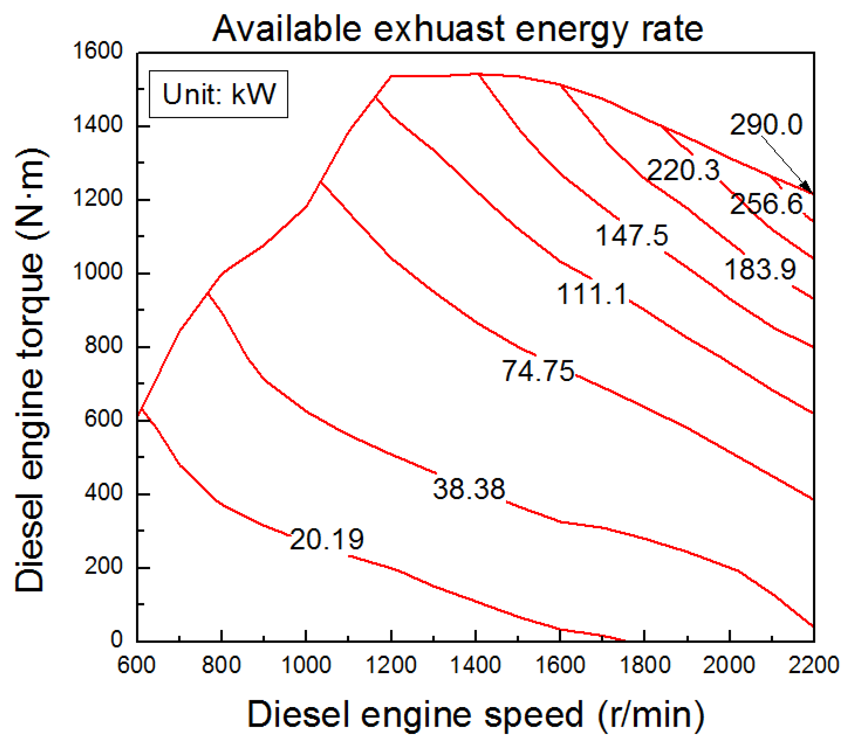
The available exhaust energy rate (Q̇ava) of the diesel engine can be calculated as follows:
The variation law of available exhaust energy rate under various operating conditions is shown in Figure 3. The engine available exhaust energy rate gradually increases with the increase of engine torque and engine speed, and the maximum of engine available exhaust energy rate is 290.0 kW. From Table 1, it is shown that the rated power of the diesel engine is 280 kW, which is lower than the maximum of engine available exhaust energy rate, so it is meaningful to recover and utilize the waste heat of the diesel engine exhaust.
2.2. Screw Expander
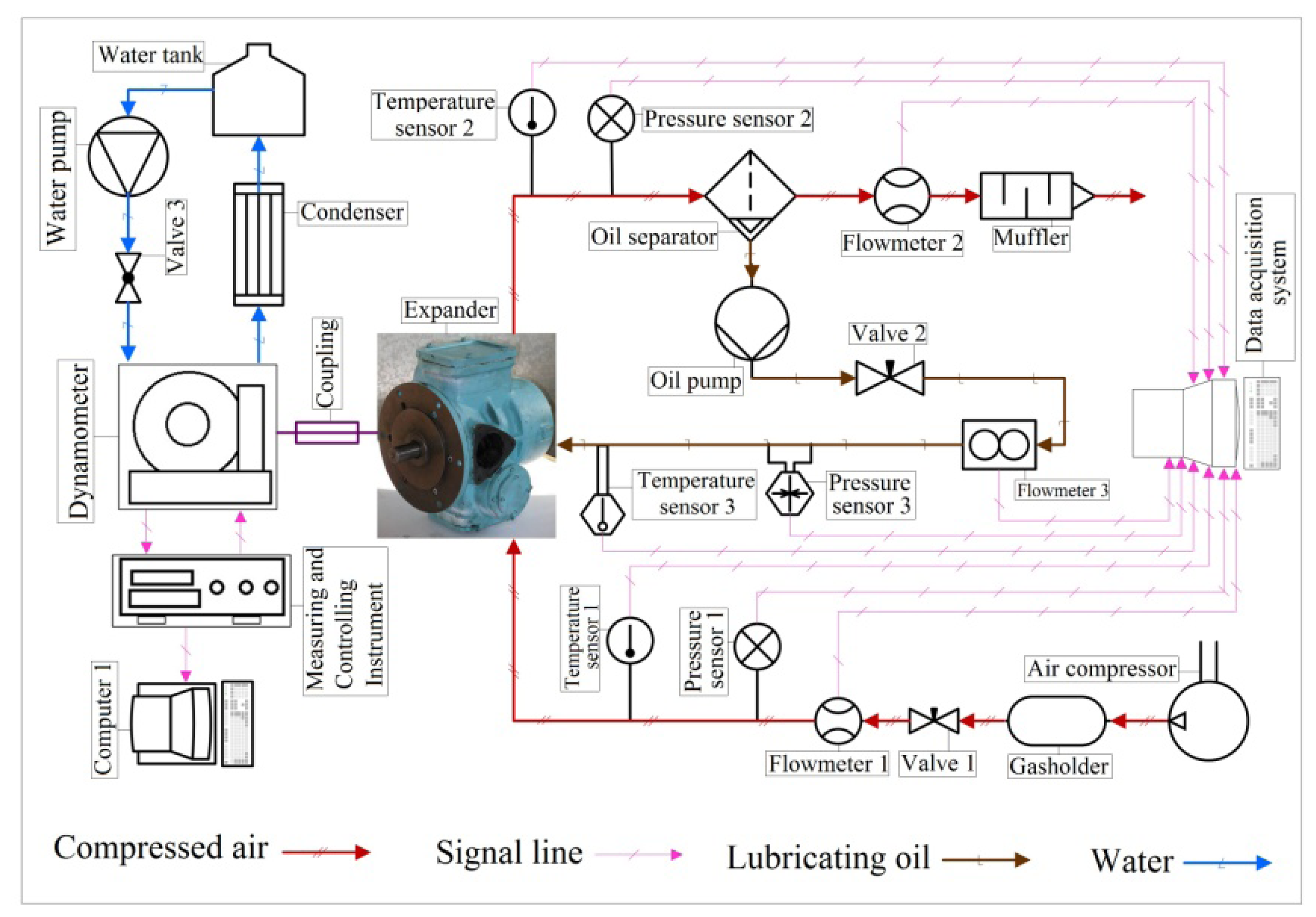
The screw expander experimental system is illustrated in Figure 4. The screw expander was designed and manufactured by our research group at the Beijing University of Technology [34–37]. The screw expander experimental system mainly consists of screw expander, working fluid (compressed air) circuit, lubricating oil circuit, power testing system, data acquisition system and water cooling system. The experiment uses compressed air as working fluid, ambient air is sucked into the compressor and pressurized, and finally be discharged to the ambient environment after the expansion process in the screw expander. The air flow rate entering the screw expander can be adjusted through the regulation valve at the outlet of the gasholder. The lubricating oil is driven by an oil pump and flows into the screw expander for the purpose of lubricating and sealing. An oil separator is used to remove lubricating oil in the air which flows out of the screw expander. An eddy current dynamometer is used to measure the power produced by the screw expander, and the water cooling system is employed to cool down the eddy current dynamometer. Different parameters, such as flow rate, inlet and outlet pressure, inlet and outlet temperature, rotational speed, torque, and power, are measured.
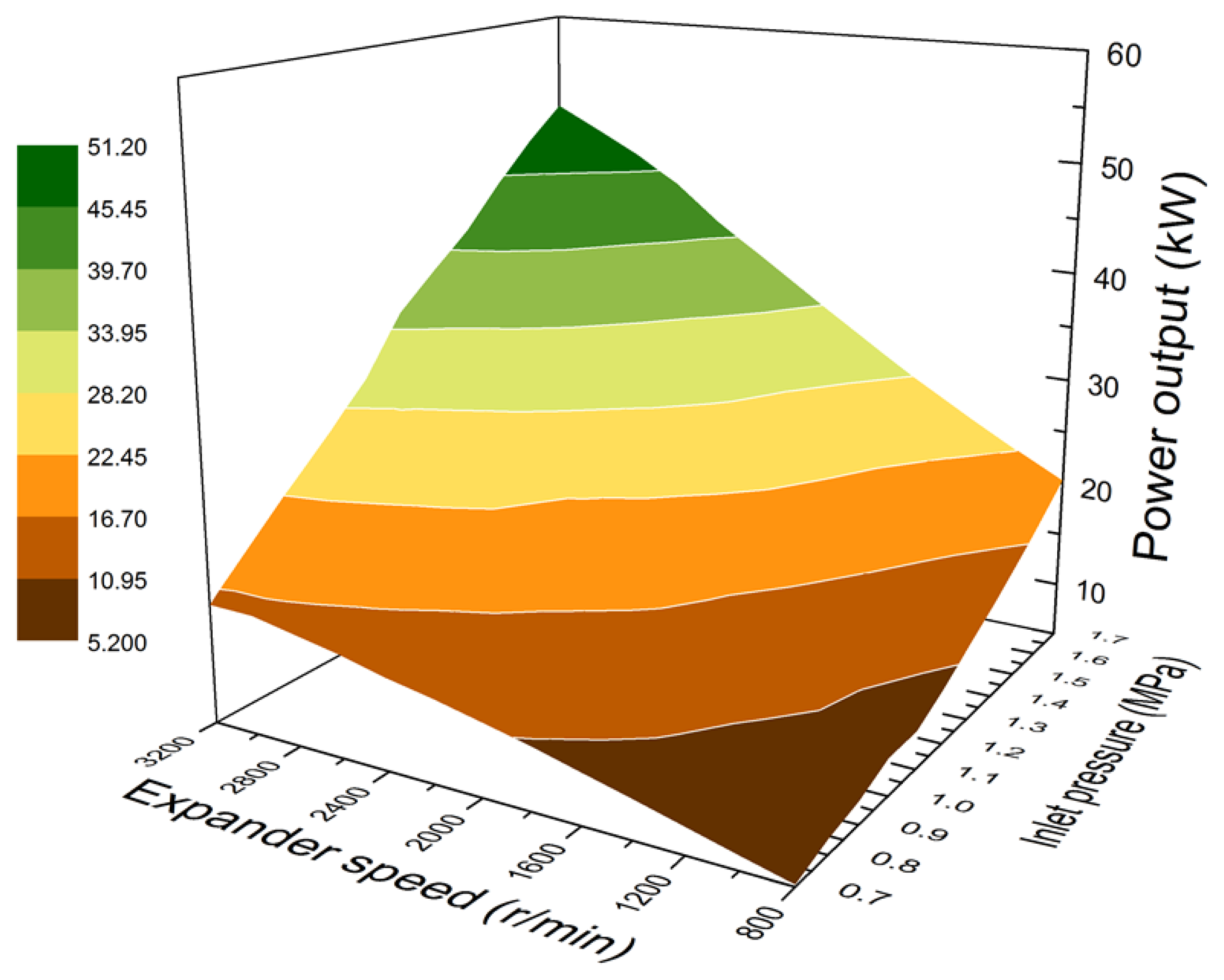
The variation of screw expander power output with the inlet pressure and rotational speed of the screw expander is shown in Figure 5. With the increase of inlet pressure and rotational speed of screw expander, the power output of the screw expander gradually increases. When the inlet pressure is 1.7 MPa and rotational speed is 3200 r/min, the power output reaches its maximum of approximately 51.20 kW.
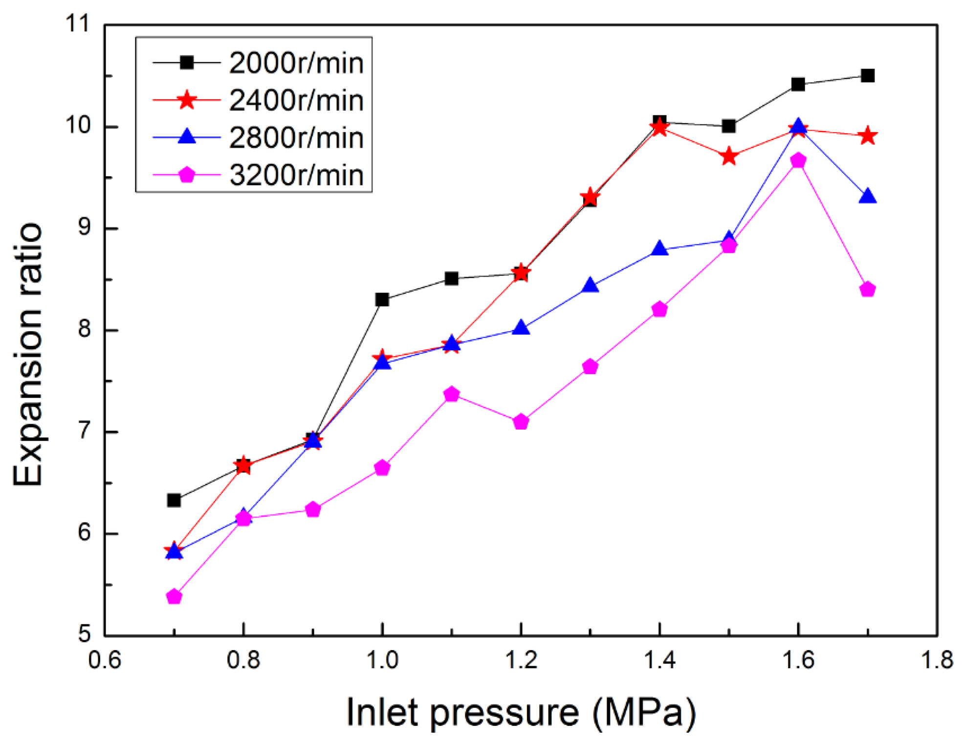
The expansion ratio is the ratio of inlet pressure to outlet pressure of the screw expander. The variation tendency of the expansion ratio with inlet pressure is shown in Figure 6, which demonstrates that the expansion ratio evidently varies with the inlet pressure and rotational speed. Overall, the expansion ratio tends to become lower with the increase of rotational speed. Furthermore, when the inlet pressure is relatively low, the expansion ratio tends to become higher with the increase of inlet pressure. When the inlet pressure is 1.7 MPa and rotational speed is 3200 r/min, the expansion ratio of the screw expander is approximately 8.
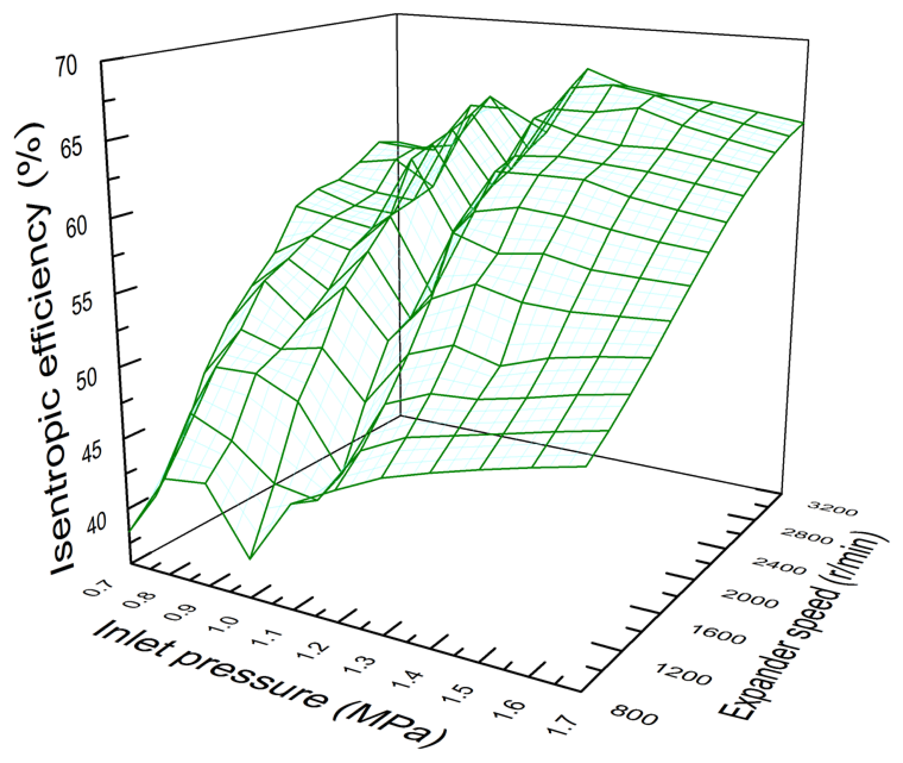
The variation of screw expander isentropic efficiency with the inlet pressure and rotational speed of the screw expander is shown in Figure 7. It can be seen that the isentropic efficiency evidently varies with the inlet pressure and rotational speed. Overall, isentropic efficiency tends to increase with the increase of rotational speed. Furthermore, when the inlet pressure is relatively high, isentropic efficiency tends to become higher with the increase of inlet pressure. When the inlet pressure is 1.7 MPa and rotational speed is 3200 r/min, the isentropic efficiency of the screw expander is approximately 0.65.
3. Vehicle Diesel Engine-ORC Combined System
3.1. Configuration of the Combined System
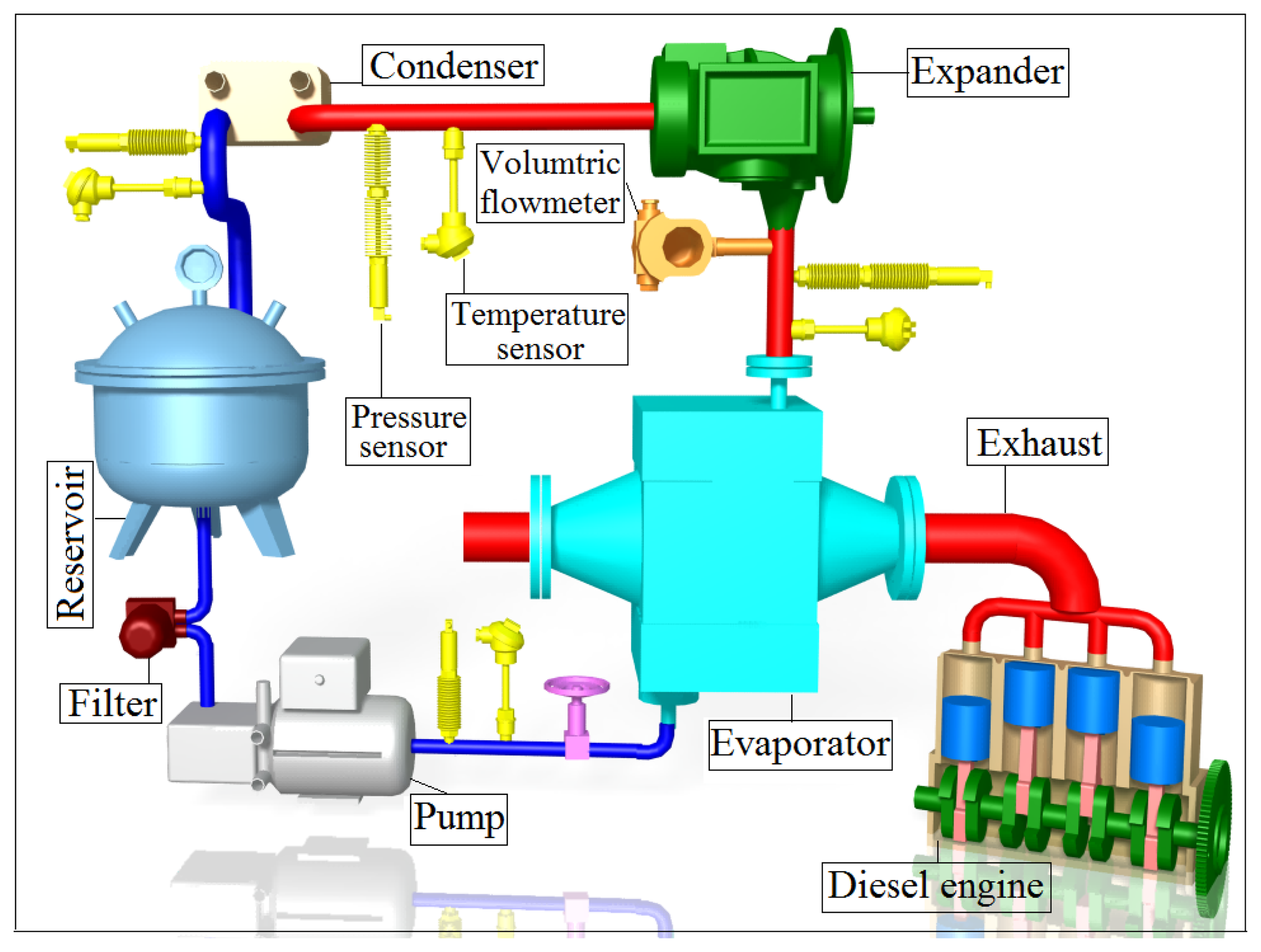
In this paper, on the basis of studying variation law of engine exhaust energy rate and running performances of the screw expander, the vehicle diesel engine-ORC combined system is presented, the combined system mainly consists two parts: vehicle diesel engine, ORC system. The working process of the vehicle diesel engine is based on the diesel cycle, whereas the working process of the ORC system is based on the Rankine cycle. For the combined system, diesel cycle is the topping cycle, and Rankine cycle is the bottoming cycle. The vehicle diesel engine-ORC combined system is illustrated in Figure 8. The ORC system mainly consists of an evaporator, screw expander, condenser, reservoir, and pump. When the ORC system is running, the working fluid is drawn from the reservoir and pressurized into a subcooled liquid state by the pump. The working fluid is then sent to the evaporator and is heated by engine exhaust. The working fluid turns into saturated vapor state with high temperature and high pressure. The saturated vapor flows into the screw expander to produce useful work. After the expansion process, with a decrease in temperature and pressure, the superheated vapor exhausted from the screw expander enters the condenser, and condenses into saturated liquid state in the condenser, then flows into the reservoir. The whole organic Rankine cycle (ORC) process is completed. R245fa is used as the working fluid for the ORC system, and its main properties are listed in Table 3.
The evaporator employed for this research is a finned-tube heat exchanger, which has a larger heat transfer area to improve the heat transfer rate between the working fluid and engine exhaust compared to a shell-and-tube heat exchanger. Moreover, a finned-tube heat exchanger has lower flow resistance. Initially, a plate heat exchanger was used as the condenser. Through some preliminary experiments, we found that the plate heat exchanger has higher flow resistance, which results in higher outlet pressure of the expander and lower net power output of the ORC system. In the next stage, we plan to use a finned-tube heat exchanger as the condenser in order to optimize the running performance of the ORC system and the combined system. At present, a multistage centrifugal pump is selected as the working fluid pump due to its merits such as stable operation, low vibration and long working life. By regulating valves installed in the pipelines, the mass flow rate of the working fluid can be effectively adjusted.
The single screw expander has many advantages, such as balanced loading of the main screw, long working life, high volumetric efficiency, high expansion ratio, low noise, low vibration and compact configuration, etc. Quite a few kinds of fluids, such as high pressure gas, superheated steam, saturated steam, gas-liquid two-phase fluid and hot liquid can be used as the working fluid for single screw expander.
3.2. Thermodynamic Model
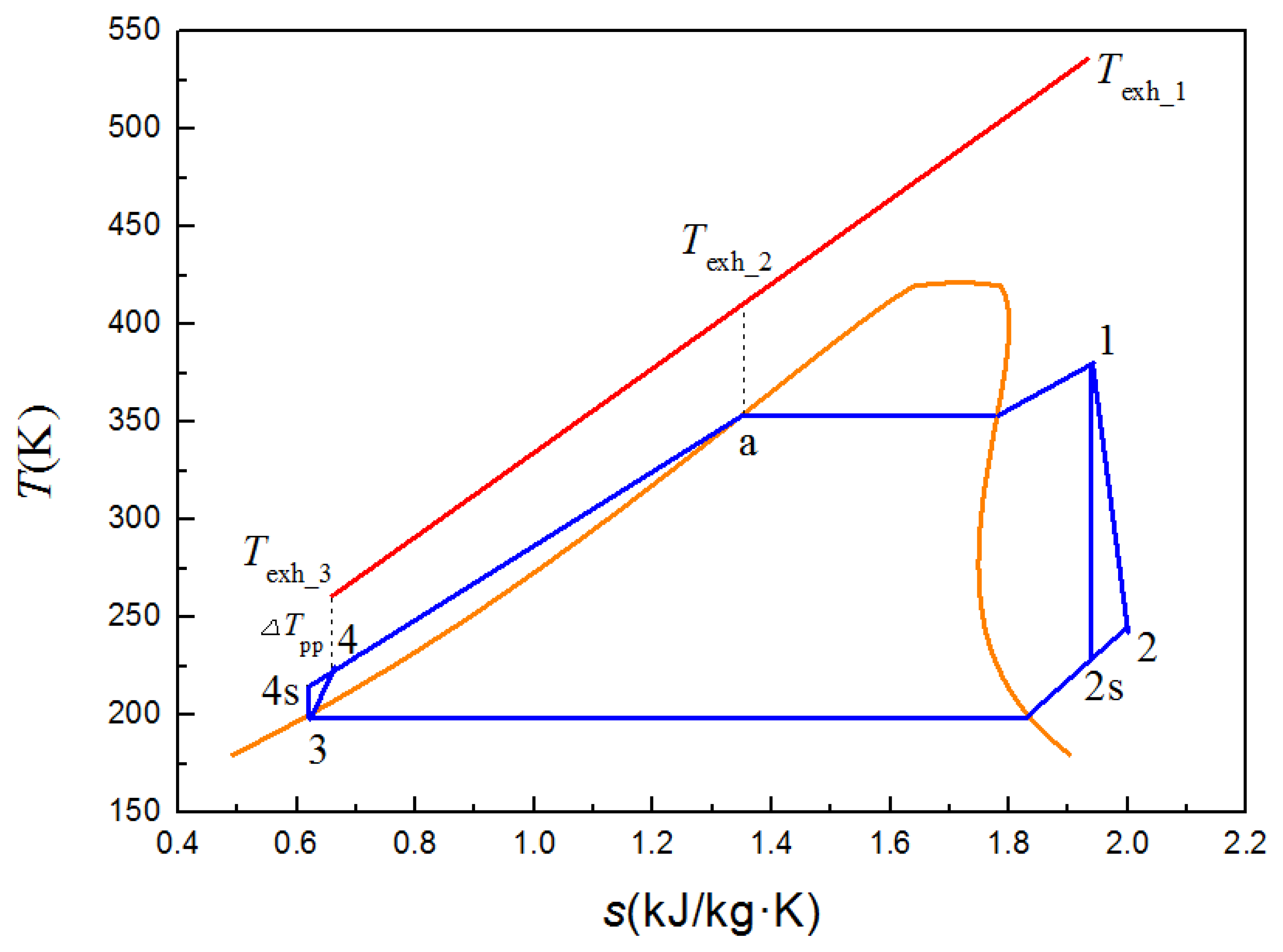
The T-s diagram of the ORC system is shown in Figure 9, where Texh_1 is the engine exhaust temperature at the inlet of the evaporator of the engine exhaust side, Texh_3 is the engine exhaust temperature at the outlet of the evaporator of the engine exhaust side, Process Texh_1 − Texh_3 is the heat rejection process of the engine exhaust in the evaporator, and ΔTpp is the pinch point temperature difference (PPTD) between the diesel engine exhaust and the working fluid R245fa, and it is set to 10 K in this paper. Process 1–2 is the actual expansion process of the working fluid in the screw expander. Process 1–2s is the isentropic expansion process. Process 2–3 is the isobaric condensing process of the working fluid in the condenser. Process 3–4 is the actual compression process of the working fluid in the pump. Process 3–4s is the isentropic compression process. Process 4–1 is the isobaric endothermic process of the working fluid in the evaporator. Because the engine exhaust temperature varies with engine operating condition, according to the different operating conditions of the diesel engine, occurrence position of pinch point temperature difference (PPTD) between the diesel engine exhaust and the working fluid R245fa may change, which may appear at the inlet of the evaporator of the working fluid side (state point 4 in Figure 9), at the outlet of the evaporator of the working fluid side (state point 1 in Figure 9), or at the saturated liquid state point of the working fluid (state point a in Figure 9). On the basis of our previous research, we can conclude that when the diesel engine torque is higher than 300 N·m, the occurrence position of pinch point temperature difference (PPTD) between the engine exhaust and working fluid certainly appears at state point 4 in Figure 9 (the inlet of the evaporator of the working fluid side). The main thermodynamic parameters of each state point of the ORC system are listed in Table 4.
The power output of the screw expander can be expressed as:
The heat transfer rate between hot fluid and cold fluid in the condenser can be expressed as:
The power consumption of the pump can be expressed as:
The heat transfer rate between hot fluid and cold fluid in the evaporator can be expressed as:
The net power output of the ORC system can be calculated as follow:
The power output of the combined system (Ẇcom) can be calculated as follow:
To objectively evaluate the running performances of the combined system, four evaluation indexes of engine thermal efficiency increasing ratio (ETEIR), waste heat recovery efficiency (WHRE), brake specific fuel consumption (BSFC) of the combined system, and improvement ratio of BSFC (IRBSFC) are proposed.
ETEIR can be calculated as follows:
WHRE can be calculated as follows:
BSFC of the combined system (bsfccom) can be calculated as follows:
IRBSFC (ηbsfc) can be calculated as follows:
From the aforementioned experimental results, it can be seen that, when the inlet pressure is 1.7 MPa and rotational speed is 3200 r/min, the expansion ratio of the screw expander is approximately 8, and the isentropic efficiency of the screw expander is approximately 0.65. Furthermore, the power output of the screw expander reaches its maximum. Thus, the above-mentioned parameter values are selected for the design operating point of the screw expander in the combined system, which indicates that the evaporating pressure of the ORC system can be set to 1.7 MPa. Moreover, for the ORC system, pressure drop and heat loss of components and pipelines are neglected, isentropic efficiency of the pump is set to 0.8, pinch point temperature difference between diesel engine exhaust and working fluid R245fa (ΔTpp) is set to 10 K.
4. Calculation Results and Discussion
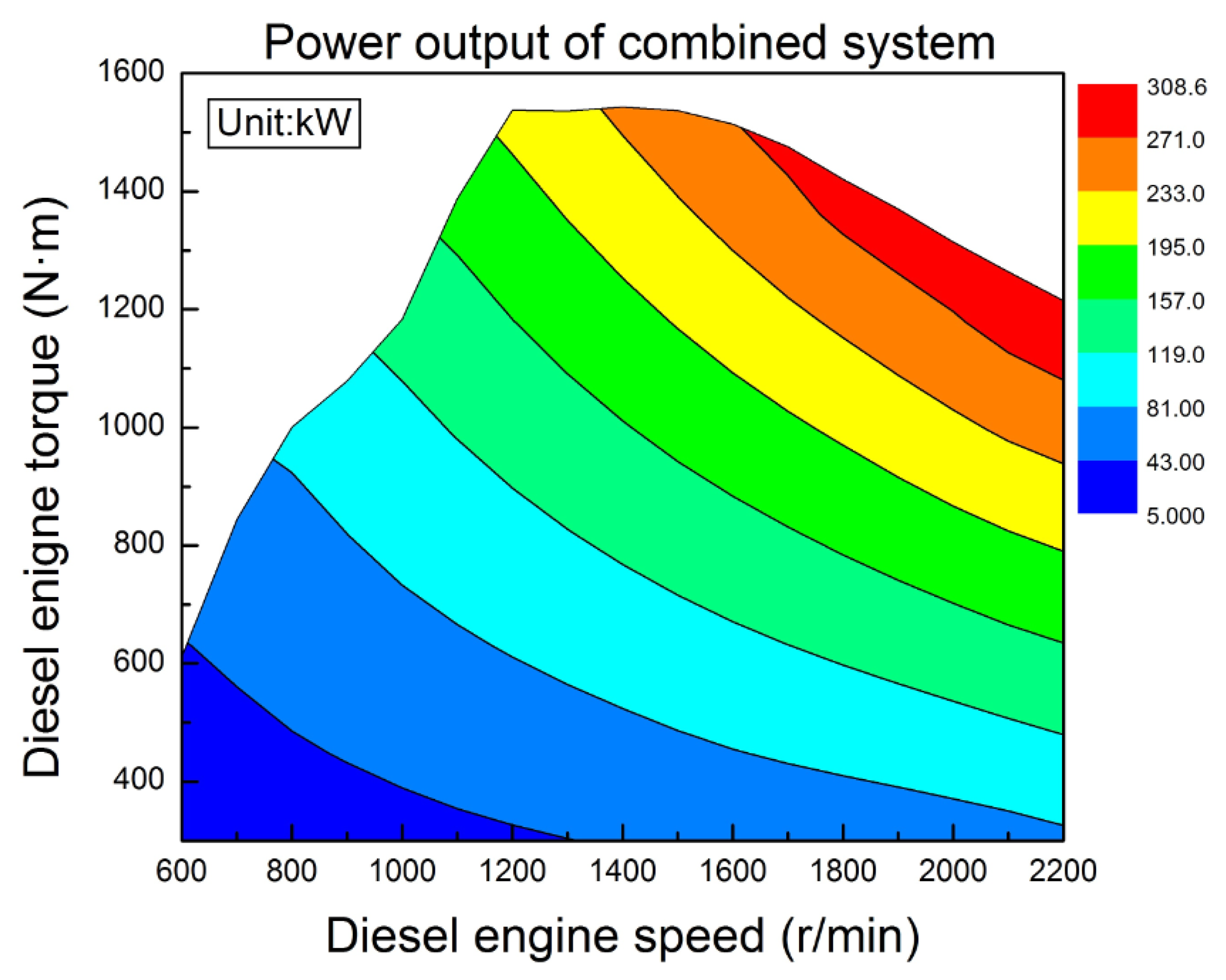
The power output of the vehicle diesel engine-ORC combined system under engine various operating conditions is shown in Figure 10. It can be concluded that, power output of the combined system gradually increases with the increase of engine speed and engine torque. The main reason for this is, with the increase of engine speed and engine torque, both power out of the diesel engine and net power output of the ORC system increase. When diesel engine speed is 2200 r/min and diesel engine torque is 1200 N·m, the power output of the combined system reaches its maximum of approximately 308.6 kW. The rated power of the diesel engine is 280 kW, and the power output of the combined system is 28.6 kW higher than that of the diesel engine.
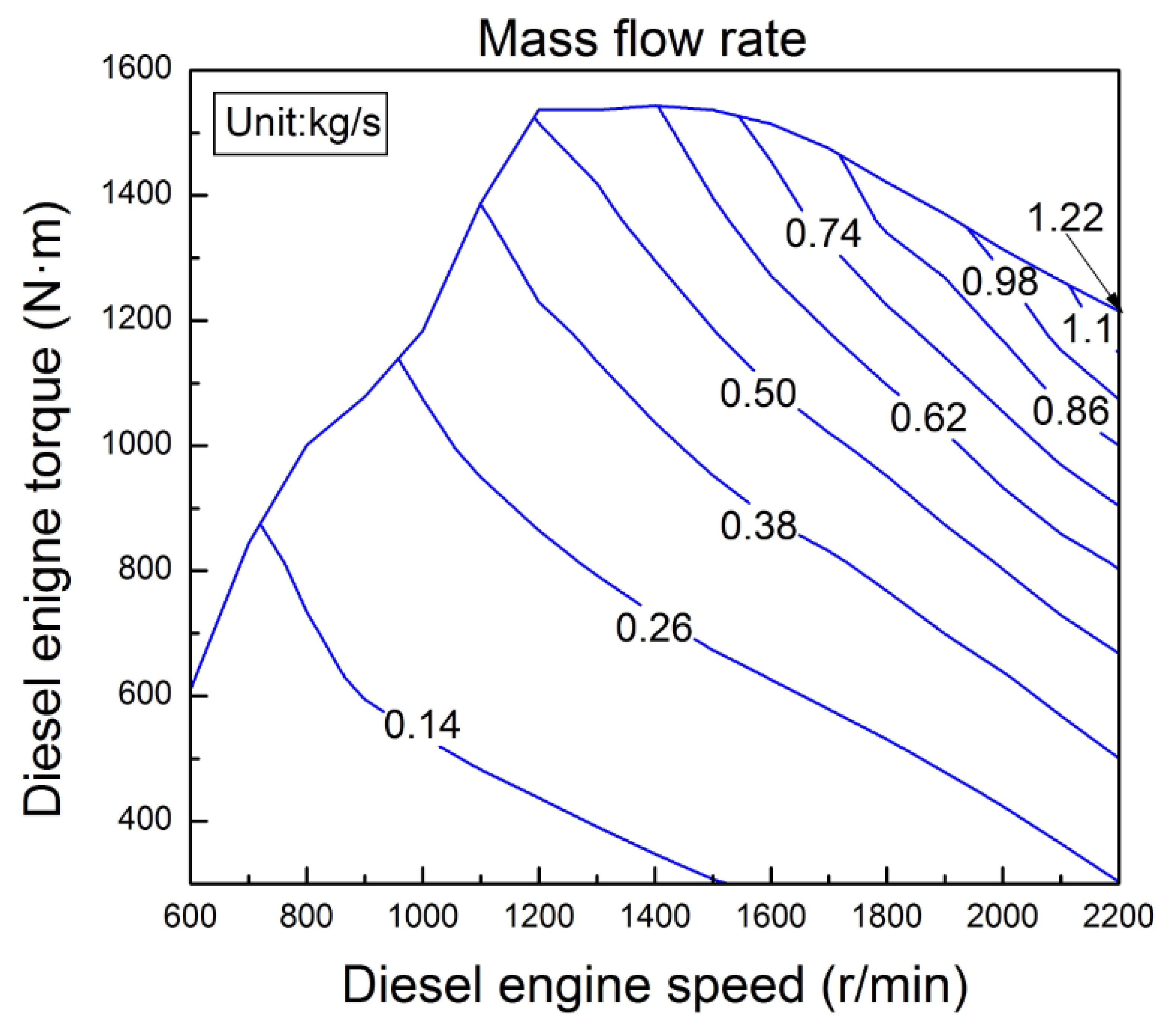
The mass flow rate variation of the working fluid R245fa under engine various operating conditions is shown in Figure 11. It can be concluded that, with the increase of engine speed and engine torque, the mass flow rate of the working fluid gradually increases. This condition can be attributed to the fact that with the increase of engine speed and engine torque, engine available exhaust energy rate increases, such that more working fluid can be heated and evaporated in the evaporator. When diesel engine speed is 2200 r/min and diesel engine torque is 1200 N·m, the mass flow rate of the working fluid reaches its maximum of approximately 1.22 kg/s. The required mass flow rate of the working fluid varies with the operating condition of the diesel engine. Considering the variation of engine available exhaust energy rate, the mass flow rate of the working fluid should be actively regulated for the corresponding operating condition of the diesel engine, which is helpful for recovering the engine exhaust energy rate efficiently and effectively. Figures 10 and 11 indicate that the distribution tendency of the contour lines of R245fa mass flow rate is similar to that of the contour lines of the combined system power output. This condition indicates that mass flow rate has an important effect on power output of the combined system under engine various operating conditions.
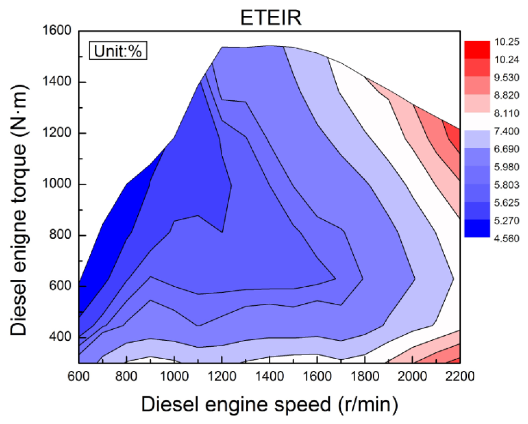
Under various operating conditions of the engine, the power output of the combined system is higher than that of the diesel engine. To assess the improvement of fuel economy and thermal efficiency, the concept of ETEIR is presented. The variation trend of ETEIR under engine various operating conditions is shown in Figure 12. When the engine torque is certain (in this paper, “certain” means “be held constant”, the same as below), ETEIR gradually increases with the increase of engine speed. When the engine speed is in the range of 600 r/min to 1200 r/min, ETEIR gradually decreases with the increase of engine torque. When the engine speed is in the range of 1200 r/min to 2200 r/min, with the increase of engine torque, ETEIR decreases initially and then increases. It can be seen that, when the diesel engine runs with high speed, ETEIR is relatively high. This observation can be attributed to several factors. First, when the diesel engine runs with high speed and low torque, the power output of the diesel engine is relatively low, and engine available exhaust energy rate is relatively high. Thus, the net power output of the ORC system is relatively high and ETEIR becomes higher. Second, when the diesel engine runs with high speed and high torque, engine available exhaust energy rate is higher, and net power output of the ORC system is higher, then ETEIR is higher. When diesel engine speed is 2200 r/min and the diesel engine torque is 1200 N·m, ETEIR reaches its maximum of approximately 10.25%.
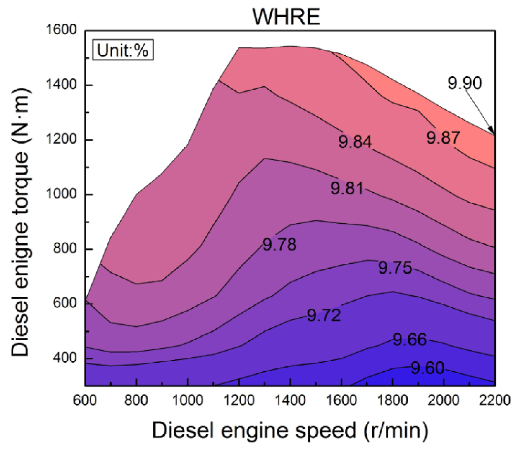
In order to assess the utilization ratio of engine available exhaust energy rate, WHRE is defined. The variation tendency of WHRE under engine various operating conditions is shown in Figure 13. When the engine speed is certain, WHRE gradually increases with the increase of engine torque. When the engine torque is in the range of 300 N·m to 400 N·m, WHRE decreases initially and then increases with the increase of engine speed. When the engine torque is in the range of 400 N·m to 1200 N·m, WHRE increases initially, then decreases, and increases anew with the increase of engine speed. When the engine torque is higher than 1200 N·m, WHRE gradually increases with the increase of engine speed. This result is mainly ascribed to the fact that both engine available exhaust energy rate and net power output of the ORC system may vary with the operating condition of the diesel engine; moreover, the amplitude of variation of the engine available exhaust energy rate may be different from the amplitude of variation of the ORC system power output. When the engine runs with high speed and high torque, WHRE is relatively high, the maximum of WHRE is approximately 9.9%.
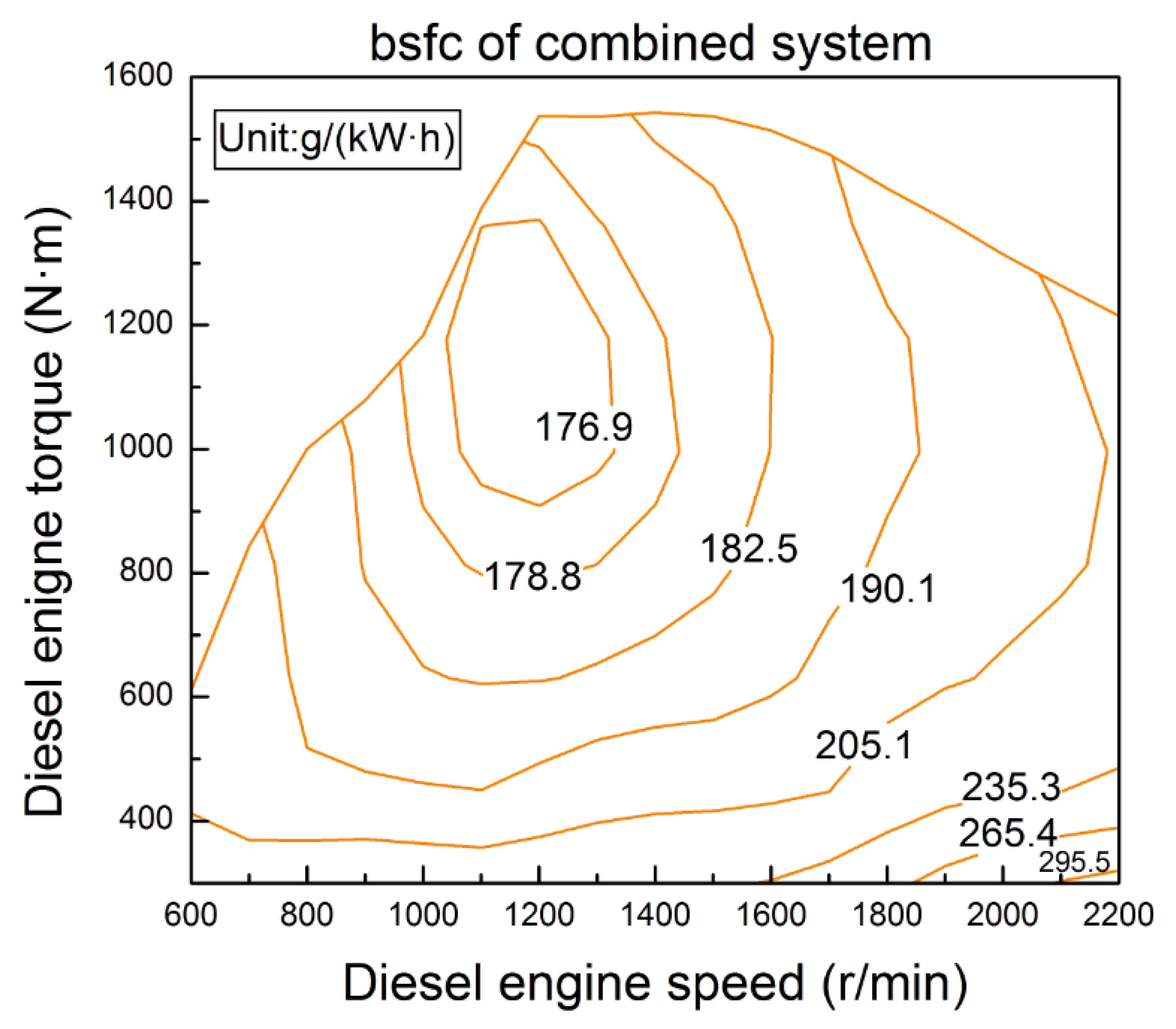
The variation tendency of the BSFC of the combined system under engine various operating conditions is shown in Figure 14. When the engine torque is in the range of 300 N·m to 1350 N·m, BSFC of the combined system decreases initially and then increases with the increase of engine speed. When the engine torque is higher than 1350 N·m, BSFC of the combined system gradually increases with the increase of engine speed. When the engine speed is in the range of 600 r/min to 1100 r/min, BSFC of the combined system gradually decreases with the increase of engine torque. When the engine speed is in the range of 1100 r/min to 2200 r/min, BSFC of the combined system decreases initially and then increases with the increase of engine torque. Figures 2 and 14 indicate that the variation tendency of the BSFC of the combined system is similar to the variation tendency of BSFC of the diesel engine. According to the same engine operating condition, the BSFC of the combined system is lower than that of the diesel engine.
IRBSFC is proposed to assess the improvement of BSFC between the combined system and the diesel engine. The variation trend of the IRBSFC under engine various operating conditions is shown in Figure 15. When the engine torque is higher than 900 N·m, IRBSFC gradually increases with the increase of engine speed. When the engine speed is in the range of 600 r/min to 1100 r/min, IRBSFC gradually decreases with the increase of engine torque. When the engine speed is in the range of 1100 r/min to 2200 r/min, IRBSFC decreases initially and then increases with the increase of engine torque. This observation is attributed to the fact that both the BSFC of the diesel engine and the net power output of the ORC system may vary with the operating condition of the diesel engine; moreover, the amplitude of variation of the diesel engine BSFC may be different from the amplitude of variation of the ORC system power output.
5. Conclusions
In this paper, a vehicle diesel engine-ORC combined system was designed, and the variation law of the engine exhaust energy rate, running performances of the screw expander, and running performances of the vehicle diesel engine-ORC combined system were studied.
- (1)
Key parameter values were determined experimentally for the design operating point of the screw expander in the combined system. The parameter values are as follows: the evaporating pressure of the ORC system is 1.7 MPa, rotational speed of the screw expander is 3200 r/min, expansion ratio of the screw expander is 8, and isentropic efficiency of the screw expander is 0.65.
- (2)
With the increase of engine speed and engine torque, the power output of the combined system gradually increases. When diesel engine speed is 2200 r/min and diesel engine torque is 1200 N·m, the power output of the combined system reaches its maximum of 308.6 kW. The rated power of the diesel engine is 280 kW, and the power output of the combined system is 28.6 kW higher than that of the diesel engine.
- (3)
According to the same engine operating conditions, the BSFC of the combined system is lower than that of the diesel engine. When diesel engine speed is 2200 r/min and diesel engine torque is 1200 N·m, ETEIR, WHRE, and IRBSFC all reach their maxima, which are 10.25%, 9.90%, and 9.30%, respectively.
- (3)
The engine available exhaust energy rate varies with engine operating conditions. In order to recover the engine exhaust energy efficiently, the mass flow rate of the working fluid should be actively regulated for the corresponding operating conditions of the diesel engine.
Acknowledgments
This work was sponsored by the National Natural Science Foundation of China (Grant No. 51376011); Scientific Research Key Program of Beijing Municipal Commission of Education (Grant No. KZ201410005003); The National Basic Research Program of China (973 Program) (Grant No. 2011CB707202); and The Twelfth Scientific Research Foundation for Graduate Students in Beijing University of Technology (Grant No. ykj–2013–9386).
Conflicts of Interest
The authors declare no conflict of interest.
References
- Shu, G.; Zhao, J.; Tian, H.; Wei, H.Q.; Liang, X.Y.; Yu, G.P.; Liu, L.N. Theoretical analysis of engine waste heat recovery by the combined thermo-generator and organic Rankine cycle system. Proceedings of SAE 2012 World Congress & Exhibition, Detroit, MI, USA, 24–26 April 2012. [CrossRef]
- Bari, S.; Hossain, S.N. Waste heat recovery from a diesel engine using shell and tube heat exchanger. Appl. Therm. Eng. 2013, 61, 355–363. [Google Scholar]
- Yun, K.T.; Cho, H.; Luck, R.; Mago, P.J. Modeling of reciprocating internal combustion engines for power generation and heat recovery. Appl. Energy 2013, 102, 327–335. [Google Scholar]
- Zhang, J.H.; Feng, J.C.; Zhou, Y.L.; Fang, F.; Yue, H. Linear active disturbance rejection control of waste heat recovery systems with organic rankine cycles. Energies 2012, 5, 5111–5125. [Google Scholar]
- Reverberi, A.; Borghi, A.D.; Dovì, V. Optimal design of cogeneration systems in industrial plants combined with district heating/cooling and underground thermal energy storage. Energies 2011, 4, 2151–2165. [Google Scholar]
- Kaska, O. Energy and exergy analysis of an organic Rankine for power generation from waste heat recovery in steel industry. Energy Convers. Manag. 2014, 77, 108–117. [Google Scholar]
- Karellas, S.; Leontaritis, A.D.; Panousis, G.; Bellos, E.; Kakaras, E. Energetic and exergetic analysis of waste heat recovery systems in the cement industry. Energy 2013, 58, 147–156. [Google Scholar]
- Wang, J.F.; Yan, Z.Q.; Zhao, P.; Dai, Y.P. Off-design performance analysis of a solar-powered organic Rankine cycle. Energy Convers. Manag. 2014, 80, 150–157. [Google Scholar]
- El-Emam, R.S.; Dincer, I. Exergy and exergoeconomic analyses and optimization of geothermal organic Rankine cycle. Appl. Therm. Eng. 2013, 59, 435–444. [Google Scholar]
- Uris, M.; Linares, J.I.; Arenas, E. Techno-economic feasibility assessment of a biomass cogeneration plant based on an Organic Rankine Cycle. Renew. Energy 2014, 66, 707–713. [Google Scholar]
- Carcasci, C.; Ferraro, R.; Miliotti, E. Thermodynamic analysis of an organic Rankine cycle for waste heat recovery from gas turbines. Energy 2014, 65, 91–100. [Google Scholar]
- Boretti, A.; Osman, A.; Aris, I. Design of Rankine cycle systems to deliver fuel economy benefits over cold start driving cycles. Proceedings of SAE 2012 International Powertrains, Fuels & Lubricants Meeting, Malmo, Sweden, 18–20 September 2012. [CrossRef]
- Glavatskaya, Y.L.; Podevin, P.; Lemort, V.; Shonda, O.; Descombes, G. Reciprocating Expander for an Exhaust Heat Recovery Rankine Cycle for a Passenger Car Application. Energies 2012, 5, 1751–1765. [Google Scholar]
- Wei, M.S.; Fang, J.L.; Ma, C.C.; Danish Syed, N. Waste heat recovery from heavy-duty diesel engine exhaust gases by medium temperature ORC system. Sci. China Technol. Sci. 2011, 54, 2746–2753. [Google Scholar]
- Xie, H.; Yang, C. Dynamic behavior of Rankine cycle system for waste heat recovery of heavy duty diesel engines under driving cycle. Appl. Energy 2013, 112, 130–141. [Google Scholar]
- Peris, B.; Navarro-Esbrí, J.; Molés, F. Bottoming organic Rankine cycle configurations to increase Internal Combustion Engines power output from cooling water waste heat recovery. Appl. Therm. Eng. 2013, 61, 364–371. [Google Scholar]
- Meinel, D.; Wieland, C.; Spliethoff, H. Effect and comparison of different working fluids on a two-stage organic Rankine cycle (ORC) concept. Appl. Therm. Eng. 2014, 63, 246–253. [Google Scholar]
- Hajabdollahi, Z.; Hajabdollahi, F.; Tehrani, M.; Hajabdollahi, H. Thermo-economic environmental optimization of Organic Rankine Cycle for diesel waste heat recovery. Energy 2013, 63, 142–151. [Google Scholar]
- Latz, G.; Andersson, S.; Munch, K. Comparison of working fluids in both subcritical and supercritical Rankine cycles for waste-heat recovery systems in heavy-duty vehicles. Proceedings of SAE 2012 World Congress & Exhibition, Detroit, MI, USA, 24–26 April 2012. [CrossRef]
- Gao, H.; Liu, C.; He, C.; Xu, X.X.; Wu, S.Y.; Li, Y.R. Performance analysis and working fluid selection of a supercritical organic Rankine cycle for low grade waste heat recovery. Energies 2012, 5, 3233–3247. [Google Scholar]
- Liu, C.; He, C.; Gao, H.; Xu, X.X.; Xu, J.L. The optimal evaporation temperature of subcritical ORC based on second law efficiency for waste heat recovery. Entropy 2012, 14, 491–504. [Google Scholar]
- Roy, J.P.; Misra, A. Parametric optimization and performance analysis of a regenerative Organic Rankine Cycle using R-123 for waste heat recovery. Energy 2012, 39, 227–235. [Google Scholar]
- Wang, E.H.; Zhang, H.G.; Fan, B.Y.; Ouyang, M.G.; Zhao, Y.; Mu, Q.H. Study of working fluid selection of organic Rankine cycle (ORC) for engine waste heat recovery. Energy 2011, 36, 3406–3418. [Google Scholar]
- Lakew, A.A.; Bolland, O. Working fluids for low-temperature heat source. Appl. Therm. Eng. 2010, 30, 1262–1268. [Google Scholar]
- Rayegan, R.; Tao, Y.X. A procedure to select working fluids for Solar Organic Rankine Cycles (ORCs). Renew. Energy 2011, 36, 659–670. [Google Scholar]
- Yagoub, W.; Doherty, P.; Riffat, S.B. Solar energy-gas driven micro-CHP system for an office building. Appl. Therm. Eng. 2006, 26, 1604–1610. [Google Scholar]
- Manolakos, D.; Papadakis, G.; Kyritsis, S.; Bouzianas, K. Experimental evaluation of an autonomous low-temperature solar Rankine cycle system for reverse osmosis desalination. Desalination 2007, 203, 366–374. [Google Scholar]
- Declaye, S.; Quoilin, S.; Guillaume, L.; Lemort, V. Experimental study on an open-drive scroll expander integrated into an ORC (Organic Rankine Cycle) system with R245fa as working fluid. Energy 2013, 55, 173–183. [Google Scholar]
- Yamada, N.; Minami, T.; Mohamad, M.N.A. Fundamental experiment of pumpless Rankine-type cycle for low-temperature heat recovery. Energy 2011, 36, 1010–1017. [Google Scholar]
- Qiu, G.Q.; Shao, Y.J.; Li, J.X.; Liu, H.; Riffat, S.B. Experimental investigation of a biomass-fired ORC-based micro-CHP for domestic applications. Fuel 2012, 96, 374–382. [Google Scholar]
- Kang, S.H. Design and experimental study of ORC (organic Rankine cycle) and radial turbine using R245fa working fluid. Energy 2012, 41, 514–524. [Google Scholar]
- Twomey, B.; Jacobs, P.A. Gurgenci, H. Dynamic performance estimation of small-scale solar cogeneration with an organic Rankine cycle using a scroll expander. Appl. Therm. Eng. 2013, 51, 1307–1316. [Google Scholar]
- Qiu, G.Q.; Liu, H.; Riffat, S.B. Expander for micro-CHP systems with organic Rankine cycle. Appl. Therm. Eng. 2011, 31, 3301–3307. [Google Scholar]
- Wang, W.; Wu, Y.T.; Ma, C.F.; Liu, L.D.; Yu, J. Preliminary experimental study of single screw expander prototype. Appl. Therm. Eng. 2011, 31, 3684–3688. [Google Scholar]
- Wang, W.; Wu, Y.T.; Ma, C.F.; Xia, G.D.; Wang, J.F. Experimental study on the performance of single screw expanders by gap adjustment. Energy 2013, 62, 379–384. [Google Scholar]
- He, W.; Wu, Y.T.; Peng, Y.H.; Zhang, Y.Q.; Ma, C.F.; Ma, G.Y. Influence of intake pressure on the performance of single screw expander working with compressed air. Appl. Therm. Eng. 2013, 51, 662–669. [Google Scholar]
- Lu, Y.W.; He, W.; Wu, Y.T.; Ji, W.N.; Ma, C.F.; Guo, H. Performance study on compressed air refrigeration system based on single screw expander. Energy 2013, 55, 762–768. [Google Scholar]
Nomenclature
| Q̇ava | available exhaust energy rate (kW) |
| Ẇice | power output of the IC engine (kW) |
| Ẇnet | net power output (kW) |
| Ẇcom | power output of the combined system (kW) |
| ΔTpp | pinch point temperature difference (K) |
| Texh_1 | exhaust temperature at evaporator inlet (K) |
| Texh_3 | exhaust temperature at evaporator outlet (K) |
| Texh_2 | exhaust temperature corresponding to the saturated liquid state zeotropic mixtures in evaporator (K) |
| ṁfuel | fuel consumption rate (kg/h) |
| ṁexh | exhaust mass flow rate (kg/s) |
| Ẇ | power (kW) |
| Q̇ | heat transfer rate (kW) |
| T | temperature (K) |
| s | entropy (kJ/kg·K) |
| P | pressure (MPa) |
| h | Enthalpy (kJ/kg) |
| ṁ | mass flow rate (kg/s) |
| Q̇fuel | fuel combustion energy rate (kW) |
| bsfccom | BSFC of the combined system (g/(kW·h)) |
| ηbsfc | improvement ratio of BSFC (%) |
| Greek letters | |
|---|---|
| ηs | isentropic efficiency of expander (%) |
| ηp | isentropic efficiency of pump (%) |
| η | efficiency (%) |
| cp | exhaust specific heat (kJ/kg·K) |
| Subscript | |
|---|---|
| 1,2,2s,3,a,4,4s, | state points in cycle (as shown in Figure 2) |
| s | expander |
| c | condenser |
| p | pump |
| e | evaporator |
| Acronyms | |
|---|---|
| ORC | organic Rankine cycle |
| BSFC | brake specific fuel consumption |
| WHRE | waste heat recovery efficiency |
| PPTD | pinch point temperature difference |
| ETEIR | engine thermal efficiency increasing ratio |
| IRBSFC | improvement ratio of BSFC |
| ODP | ozone depletion potential |
| GWP | global warming potential |


| Item | Parameter | Unit |
|---|---|---|
| Displacement | 9726 | mL |
| Cylinder diameter | 126 | mm |
| Stroke | 130 | mm |
| Rated speed | 2200 | r/min |
| Maximum torque | 1500 | N·m |
| Rated power | 280 | kW |
| Compression ratio | 17 | - |
| Engine speed (r/min) | Engine torque (N·m) | Engine power (kW) | Fuel consumption rate (kg/h) | Intake air flow rate (kg/h) | Engine exhaust temperature (K) |
|---|---|---|---|---|---|
| 2200 | 1214.9 | 279.87 | 66.01 | 1661.6 | 818.95 |
| 2000 | 1313.9 | 275.17 | 60.97 | 1554.2 | 783.45 |
| 1800 | 1420.8 | 267.8 | 56.7 | 1432.4 | 779.85 |
| 1600 | 1514 | 253.67 | 50.76 | 1252.4 | 745.95 |
| 1400 | 1543.2 | 226.24 | 44.14 | 1090.1 | 710.75 |
| 1200 | 1537.3 | 193.18 | 36.83 | 918.4 | 704.05 |
| 1000 | 1183.6 | 123.95 | 23.18 | 595.4 | 650.75 |
| 800 | 1001 | 83.86 | 16.38 | 361.7 | 653.95 |
| 600 | 610.9 | 38.38 | 8.24 | 214.7 | 568.85 |
| Working fluid | Chemical formula | Molar mass (kg/kmol) | Tcritical (K) |
|---|---|---|---|
| R245fa | CHF2CH2CF3 | 134.05 | 427.16 |
| Pcritical (MPa) | ρcritical (kg/m3) | ODP | GWP (100 years) |
| 3.651 | 516.08 | 0.0 | 950 |
| Parameters | State point 1 | State point 2 | State point 2s | State point 3 | State point 4 | State point 4s |
|---|---|---|---|---|---|---|
| Temperature [K] | 386.973 | 335.251 | 321.653 | 308.258 | 309.027 | 308.815 |
| Pressure [MPa] | 1.700 | 0.213 | 0.213 | 0.213 | 1.700 | 1.700 |
| Enthalpy [kJ·kg−1] | 481.637 | 456.767 | 443.376 | 245.952 | 247.369 | 247.086 |
| Entropy [kJ·(kg·K)−1] | 1.797 | 1.838 | 1.797 | 1.157 | 1.158 | 1.157 |
© 2014 by the authors; licensee MDPI, Basel, Switzerland. This article is an open access article distributed under the terms and conditions of the Creative Commons Attribution license ( http://creativecommons.org/licenses/by/3.0/).
Share and Cite
Yang, K.; Zhang, H.; Song, S.; Zhang, J.; Wu, Y.; Zhang, Y.; Wang, H.; Chang, Y.; Bei, C. Performance Analysis of the Vehicle Diesel Engine-ORC Combined System Based on a Screw Expander. Energies 2014, 7, 3400-3419. https://doi.org/10.3390/en7053400
Yang K, Zhang H, Song S, Zhang J, Wu Y, Zhang Y, Wang H, Chang Y, Bei C. Performance Analysis of the Vehicle Diesel Engine-ORC Combined System Based on a Screw Expander. Energies. 2014; 7(5):3400-3419. https://doi.org/10.3390/en7053400
Chicago/Turabian StyleYang, Kai, Hongguang Zhang, Songsong Song, Jian Zhang, Yuting Wu, Yeqiang Zhang, Hongjin Wang, Ying Chang, and Chen Bei. 2014. "Performance Analysis of the Vehicle Diesel Engine-ORC Combined System Based on a Screw Expander" Energies 7, no. 5: 3400-3419. https://doi.org/10.3390/en7053400
APA StyleYang, K., Zhang, H., Song, S., Zhang, J., Wu, Y., Zhang, Y., Wang, H., Chang, Y., & Bei, C. (2014). Performance Analysis of the Vehicle Diesel Engine-ORC Combined System Based on a Screw Expander. Energies, 7(5), 3400-3419. https://doi.org/10.3390/en7053400