Performance Evaluation of a Solar Adsorption Refrigeration System with a Wing Type Compound Parabolic Concentrator

Abstract
: Simulation study of a solar adsorption refrigeration system using a wing type compound parabolic concentrator (CPC) is presented. The system consists of the wing type collector set at optimum angles, adsorption bed, a condenser and a refrigerator. The wing type collector captures the solar energy efficiently in the morning and afternoon and provides the effective temperature for a longer period of time compared to that achieved by a linear collector. The objectives of the study were to evaluate the system behavior, the effect of wing length, and to compare the performance of the systems with wing type and linear CPCs. A detailed dynamic simulation model was developed based on mass and energy balance equations. The simulation results show that the system performance with wing type CPC increases by up to 6% in the summer and up to 2% in the winter, compared to the performance with a linear CPC having same collector length. The ice production also increases up to 13% in the summer with the wing type CPC. This shows that the wing type CPC is helpful to increase the performance of the system compared to the linear CPC with the same collector length and without the need for tracking.1. Introduction
The advancement of technology has made cooling a part of life. Therefore, the rapidly growing population and changing life style in developing areas has also increased the demand for cooling for various purposes, for example, for storing foods and medicines, cold water for drinking, and for space cooling. Normally electric driven systems are used for refrigeration or cooling purposes, but the energy shortfall and lack of or insufficient electric supplies are the main constrains to use electric driven cooling systems in such developing areas. Therefore, the use of solar energy as an alternative source of energy for cooling is increasing due to the energy crises and the rapid depletion of existing non-renewable resources [1–3]. Solar cooling can be promising and attractive technique in the future because of the near coincidence of peak cooling loads with the available solar power. There are many solar cooling techniques like absorption, adsorption, desiccant, and ejector systems. Solar adsorption refrigeration has advantages over other systems, such as it can be driven with low heat [4], it does not require electric power, the systems are easily operated and require less maintenance, and moreover, the working pairs used in the systems are environmentally friendly [5]. Therefore, solar adsorption cooling systems seem technologically possible and socially feasible in such areas where there is not enough electricity, but solar energy is rather easy to obtain.
Despite their potential advantages, the existing solar adsorption refrigeration systems are not yet competitive enough to replace electricity-driven refrigerators because of their low efficiency, intermittent operation, and high initial cost. In the present study, a contribution to improve the efficiency of solar adsorption refrigeration systems by using a wing type compound parabolic concentrator (CPC), proposed by the present authors in the previous publication [6], is added to the body of literature on this topic.
Solar collector is an important part in the solar adsorption chiller because it provides the driving energy for system operation. Flat-plate collectors are commonly used in solar adsorption refrigeration systems [7–10]. Some attention has also been given to using concentrator collectors [11,12], specifically CPCs [13,14]. CPCs can achieve higher temperatures compared to flat-plate collectors, and it has also been reported that CPCs have the ability to produce ice with a solar adsorption ice maker even on overcast days [14]. Many studies have been conducted that describe the techniques to improve the solar energy collection performance [15–17]. These techniques either involved special designs and operations or are not suitable for solar driven adsorption chillers. Normally, solar collectors are straight, facing south. In this case the required temperature is obtained in the middle of the day. To obtain the required temperature for longer period of time, the solar energy needs to be captured efficiently in the morning and afternoon. For this purpose, the present authors have proposed a novel CPC with wings that provided the effective temperature for longer period of time compared to a linear CPC with same length [6]. The proposed collector works without the need of tracking or a heat storage tank, and does not involve any extra design and operation.
In this study, a solar adsorption refrigerator equipped with the proposed wing type CPC is investigated. The objectives of the study were to investigate the behavior of a conventional intermittent solar adsorption refrigeration system with proposed wing type CPC, to investigate the effect of length of wings, and to compare the performance of the system with the proposed wing type CPC and with a linear CPC. Because the proposed wing type collector can provide the effective temperature for a longer period of time, therefore, it will help to obtain more amount of desorbed refrigerant by the end of the day that will contribute to improve the overall performance of the system.
2. CPC
A CPC is a non-imaging concentrator that consists of two parabolas and one absorber. The absorber may be flat or tubular; the geometry of the CPC profile depends on the shape of the receiver selected. In the current study, a two-dimensional (2D) CPC with a partially exposed tubular absorber was used. Partially exposed receivers have been reported to be favorable for solar adsorption cooling applications as they have the advantage of heat rejection from the back side during the adsorption process and increased adsorbent per unit area [13]. Normally, a CPC does not require tracking and it can accept incoming radiation over a relatively wide range of angles by using multiple reflections [18].
Proposed CPC with Wings
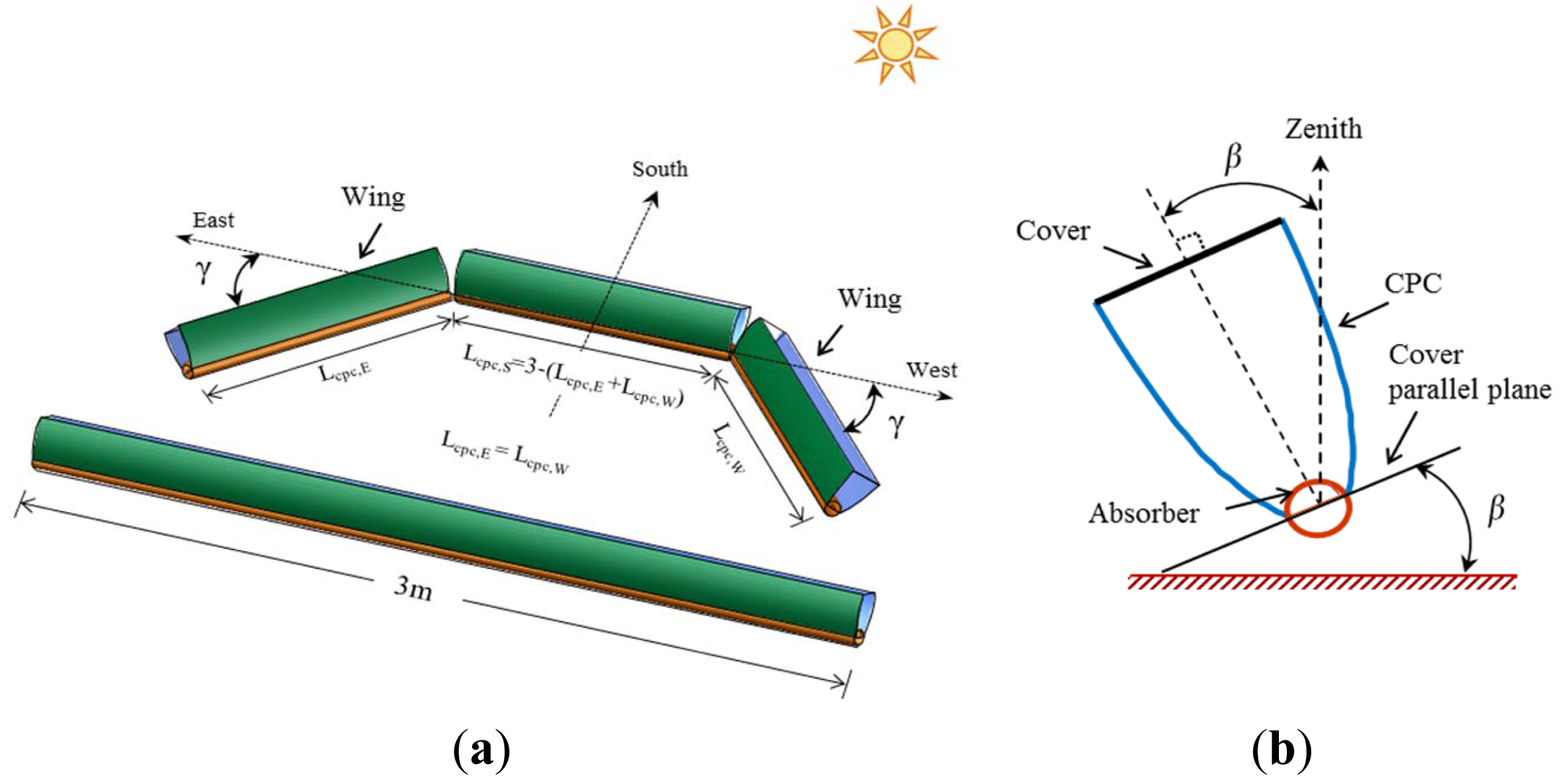
A CPC with wings angled towards the east and west was proposed by the present authors [6]. The shape of the wing type CPC is shown in Figure 1. The length of the proposed CPC is the same as for a linear CPC, but it is divided into three parts. The ends are termed wings and are angled toward the east and west (surface azimuth angle) to capture maximum solar energy during various times of day.
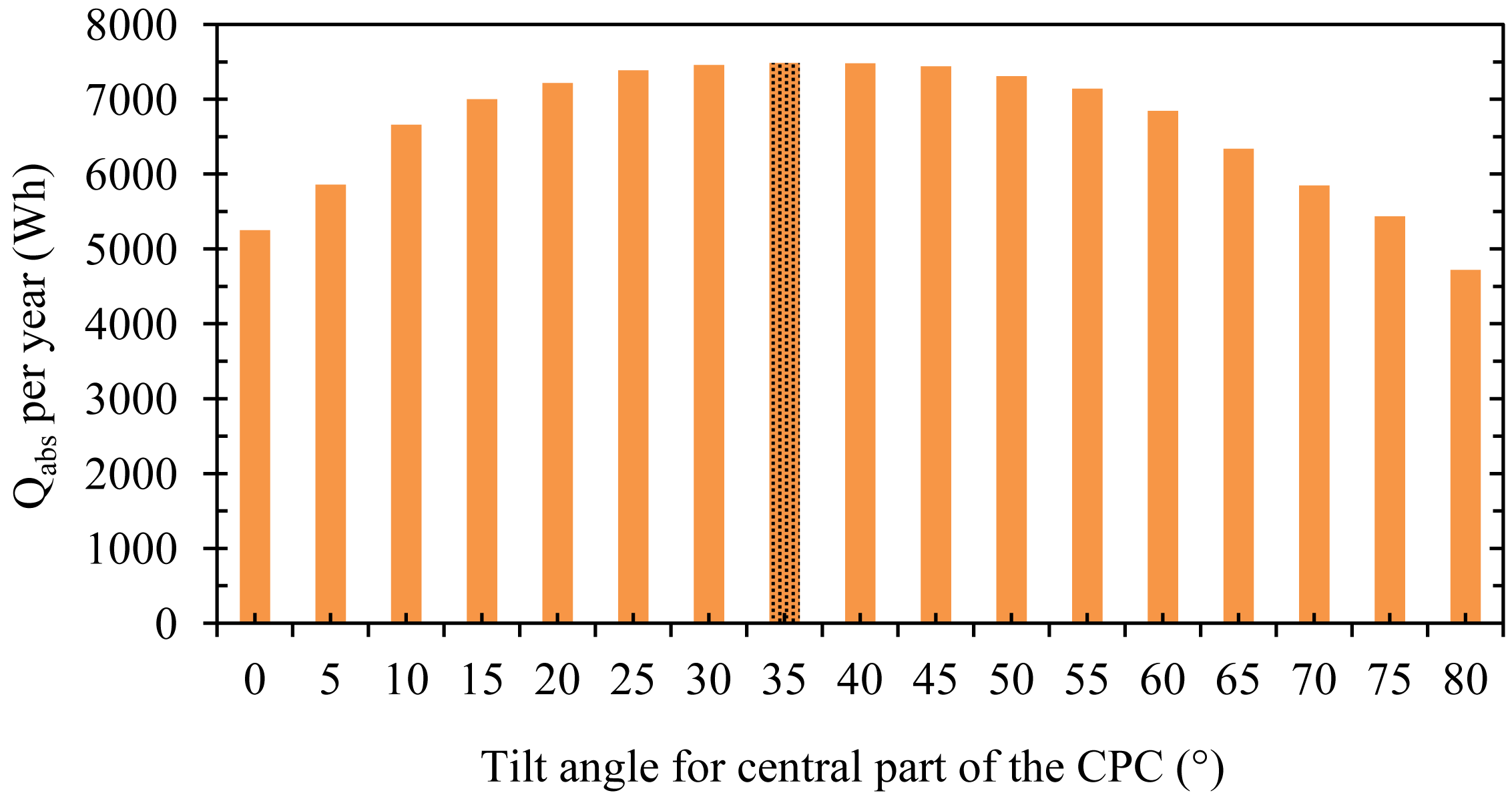
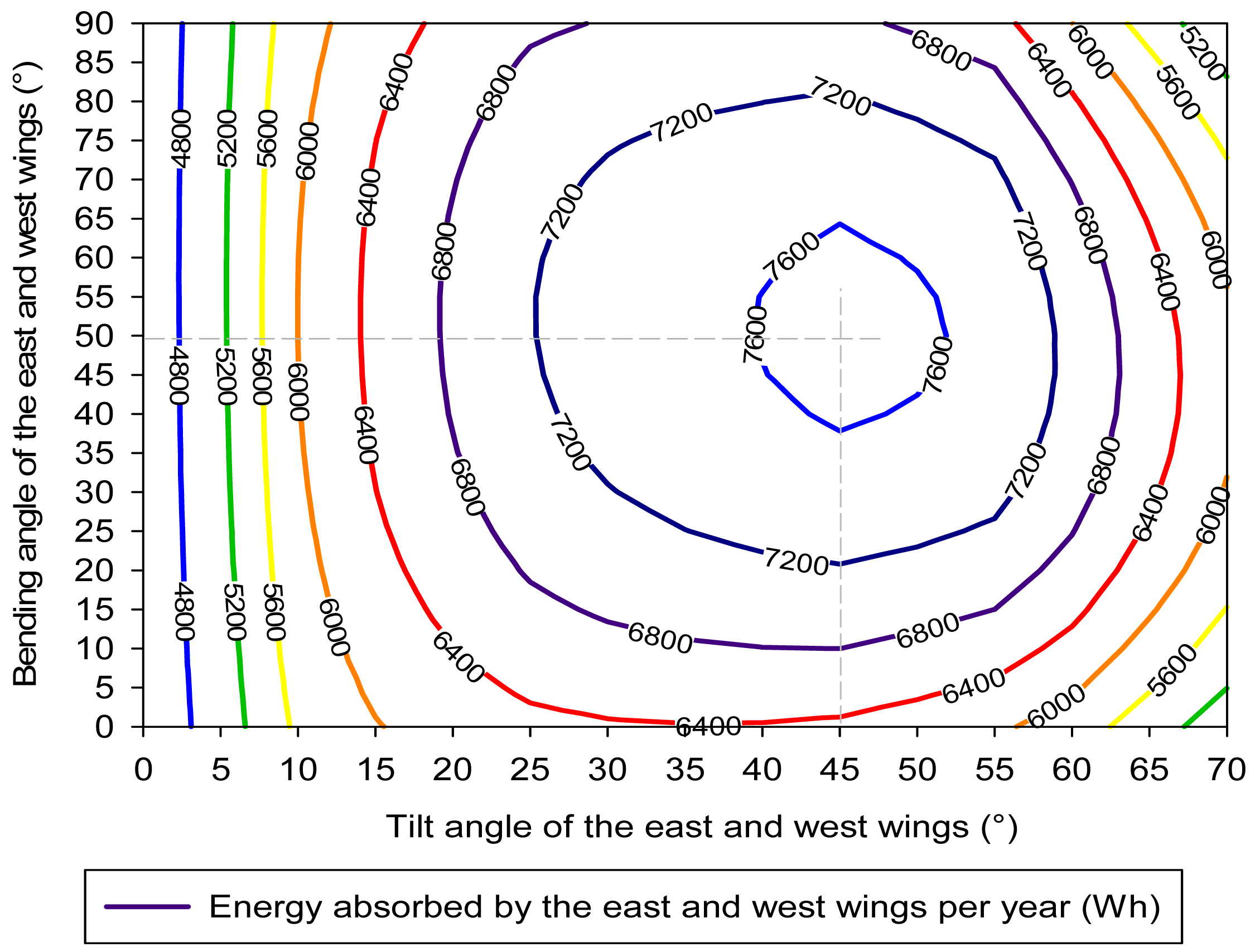
The tilt and bending angles of the CPC wings were optimized by analyzing the energy absorbed at the CPC absorber for a sunny day from each month. A 35° tilt for the south-facing central part of the CPC and a 45° tilt for the wings with 50° angles toward the east and west were found to be optimal for the location of Tokyo, Japan (Figures 2 and 3). It was found that the proposed CPC can provide the effective temperature for a longer period of time compared to the conventional linear CPC. The duration of the effective temperatures increased by up to 2 h in the winter and up to 2.53 h in the summer using the proposed CPC. Therefore, the proposed CPC with wings was used with a solar adsorption refrigerator to investigate the effect on performance of the system.
3. System Description
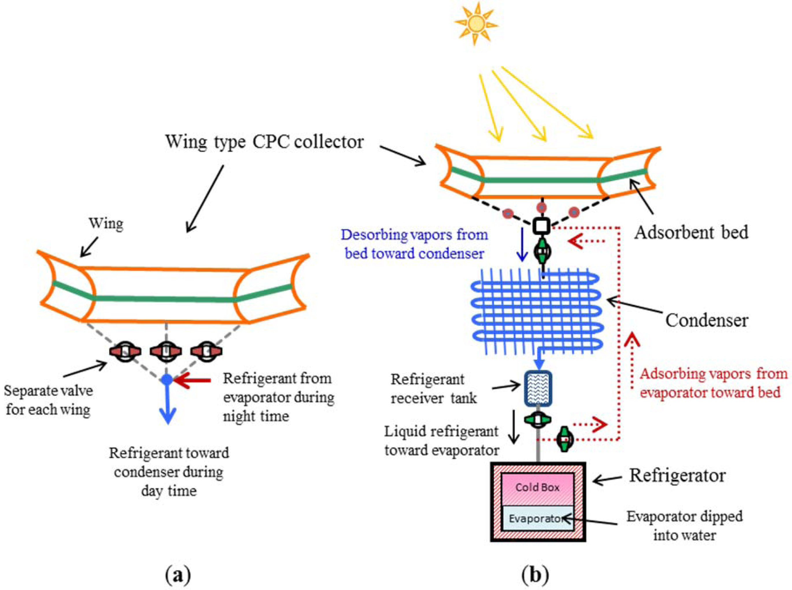
The working principle of the system is based on the adsorption desorption property of the working pair. Activated carbon fiber (ACF, adsorber) and ethanol (refrigerant) were used as the working pair (adsorbent bed). The activated carbon fiber is a recently developed adsorbent that is more efficient than ordinary activated carbon [19]. The present adsorption refrigerator works according to conventional intermittent cycle that produces cooling during the night time only. The system consists of a CPC collector with an adsorbent bed directly packed into the absorber tube, air cooled condenser and refrigerator (Figure 4). In the refrigerator the evaporator is dipped into the water that converts into ice when evaporator temperature becomes 0 °C or below during the cooling process. The ice acts as cold storage and keeps the cold box at a low temperature.
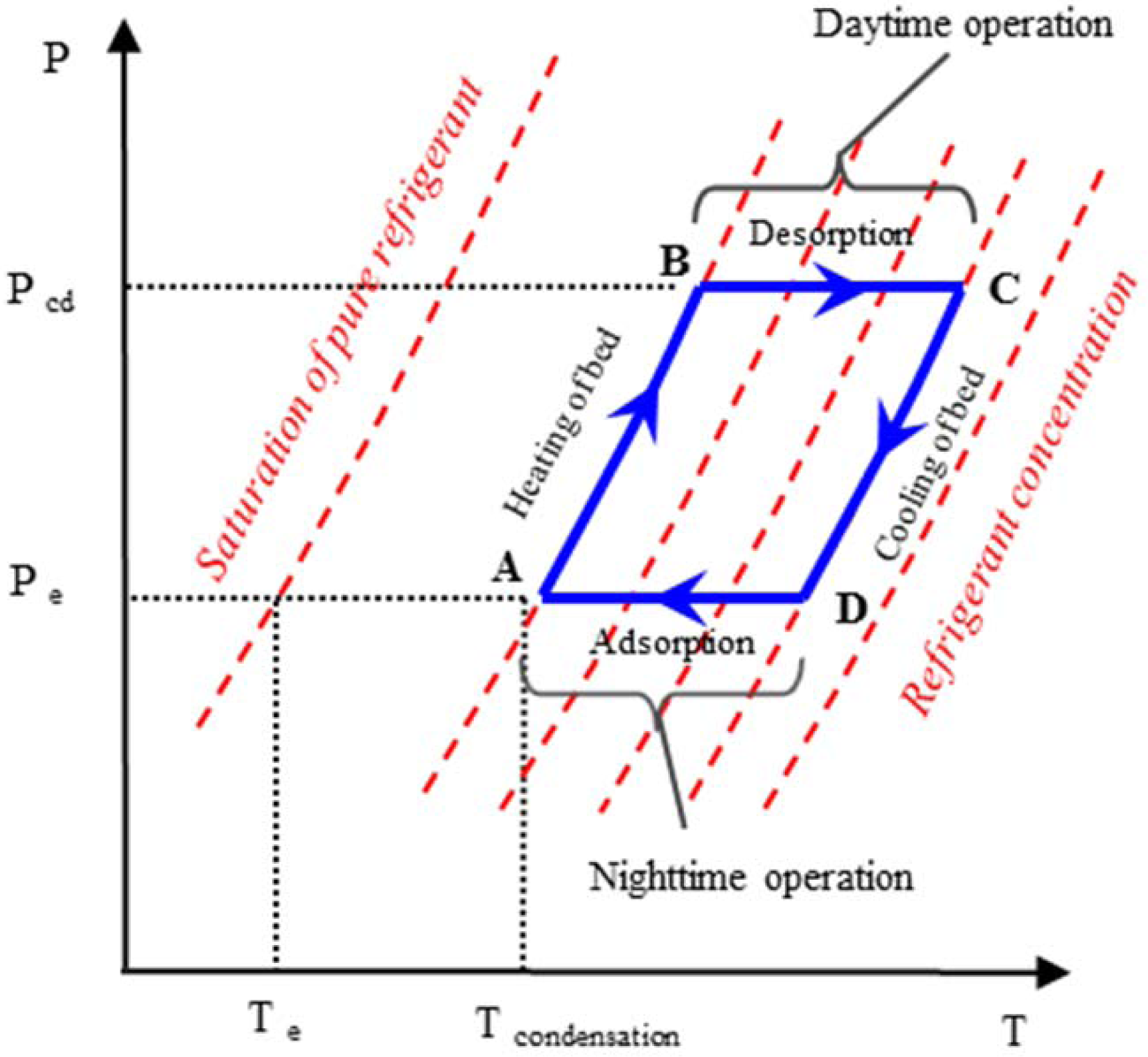
The working cycle of the system can be explained by the ideal Duhring (P-T-X) diagram as shown in Figure 5.
The cycle starts from Point A when the sun rises and the collector heated up the adsorbent bed (A–B)—this is called pre-heating. At a certain Point B, when the adsorbent bed pressure becomes equal to the condensation pressure of the refrigerant, the refrigerant starts desorbing from the adsorbent in vapor form. The adsorbent beds are connected to the condenser where the refrigerant is condensed and collected in the receiver tank while the adsorbent beds are continuously heated at a constant pressure (B–C)—this stage is called desorption. In the late afternoon (Point C) when the solar radiations are not enough to continue the desorption process further, the adsorbent beds are disconnected from the condenser. The temperature and pressure of the beds start decreasing in the evening (C–D)—this stage is called pre-cooling. When the pressure of the beds reaches the evaporation pressure, the adsorbent beds are connected to the evaporator (D–A)—this is adsorption stage. The liquid refrigerant from the receiver tank is allowed to enter the evaporator through the expansion valve where it evaporates and again adsorbed in the adsorbent beds. Evaporation cause cooling in the evaporator that makes ice, and this ice keeps the cold box at a low temperature. In sum, the system is operated with a cycle time of 24 h.
4. Mathematical Models
4.1. Assumptions
A detailed dynamic simulation model was used to predict the temperatures of the CPC cover and absorber [6,20,21], adsorption system, and for the performance evaluation [22–25]. The model was based on mass and energy balance equations. The following assumptions were made to simplify the model:
The CPC is ideal and free from any fabrication errors;
Each part of the CPC is an independent unit;
The temperature is uniformly distributed in the heat exchangers;
The bottom side of the absorber is well-insulated, and there is no heat loss to the surroundings;
The adsorbent particles have uniform size, shape and distribution;
The pressure is uniform in refrigerant flowing channel;
All specific heats of the components and coefficient of heat transfer are assumed to be constant.
4.2. Governing Equations
The adsorption rate is given by:
The CPC cover temperature is given by:
The CPC absorber temperature is given by:
In Equations (6) and (8), the term on the left-hand side is the sensible heat and the terms of the form h·ΔT on the right-hand side are the heat transfers by radiation, convection, and wind from the cover and receiver of the CPC. Methods for calculating θi, θz, γs, hRr, hrc, hRs and hca are given reference [6]. The numerical values used in the simulation are given in Table 1.
The adsorbent bed temperature during desorption is given by:
The adsorbent bed temperature during adsorption is given by:
The condenser temperature is given by:
The evaporator temperature is given by:
The water temperature in the refrigerator is given by:
The ice production is given by:
The mass balance is given by:
4.3. Performance Index
The performance of the system was evaluated in terms of specific cooling effect (SCE) that is calculated as:
4.4. Initial Conditions
Initial conditions were as follows:
4.5. Boundary and Operating Conditions
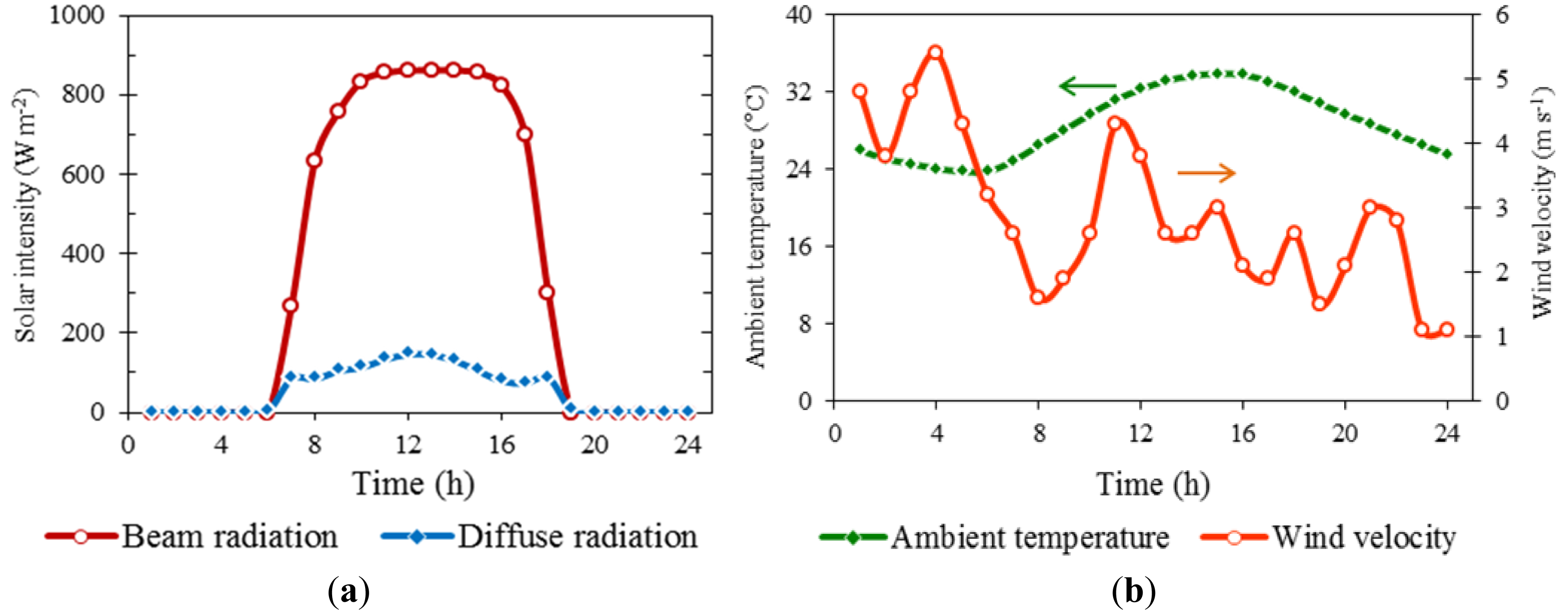
Actual measured solar radiation, ambient temperature, and wind velocity data for Tokyo were used in the simulation (Figure 6). To evaluate year-round performance, weather data for one sunny day in each month were selected. The data were obtained from the commercial software Meteonorm V. 6.1.
4.6. Numerical Solution of the Mathematical Models
Mathematical models developed for different components of the system were used to compile a computer algorithm with the commercial software MATLAB R2010b. The Ordinary Differential Solver (ODE45) tool was used to incorporate the differential equations into the simulation model. Graphs were prepared in Microsoft Excel and SigmaPlot using the simulation results from MATLAB.
5. Results and Discussion
5.1. System Behavior with Wings Type CPC
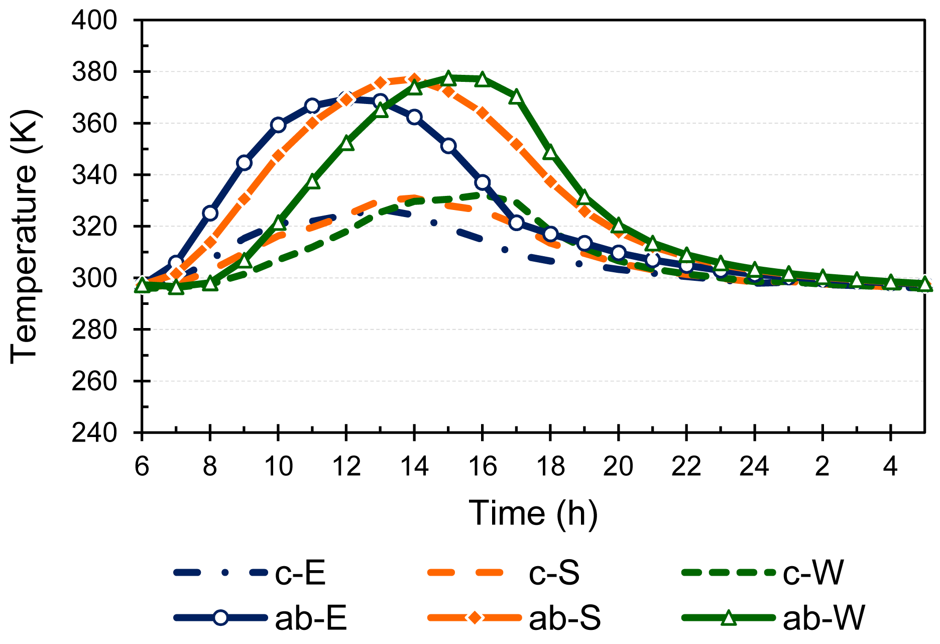
A conventional intermittent solar adsorption refrigeration system was investigated with a wing type CPC that was previously proposed by the present authors. The optimum settings for tilt and bending angles of wings were used for the proposed CPC. The system was operated with separate valve control for each wing. Figure 7 shows the temperatures of the CPCs cover and absorber. It can be seen that the each wing is showing a different temperature profile according to its orientation. The absorber of the east wing achieves a higher temperature in the morning compared to the other wings; similarly the west wing absorber achieves a higher temperature in the afternoon. Therefore, the effective temperature is obtained for a longer period of time compared to the standard linear south-facing CPC. The peak temperature (around 380 K) is the highest in the west wing, because the solar radiation was also high in the afternoon and the west wing captures the radiation efficiently duet to its bending angle toward the west. The cover temperature follows a trend similar to the absorber temperature.
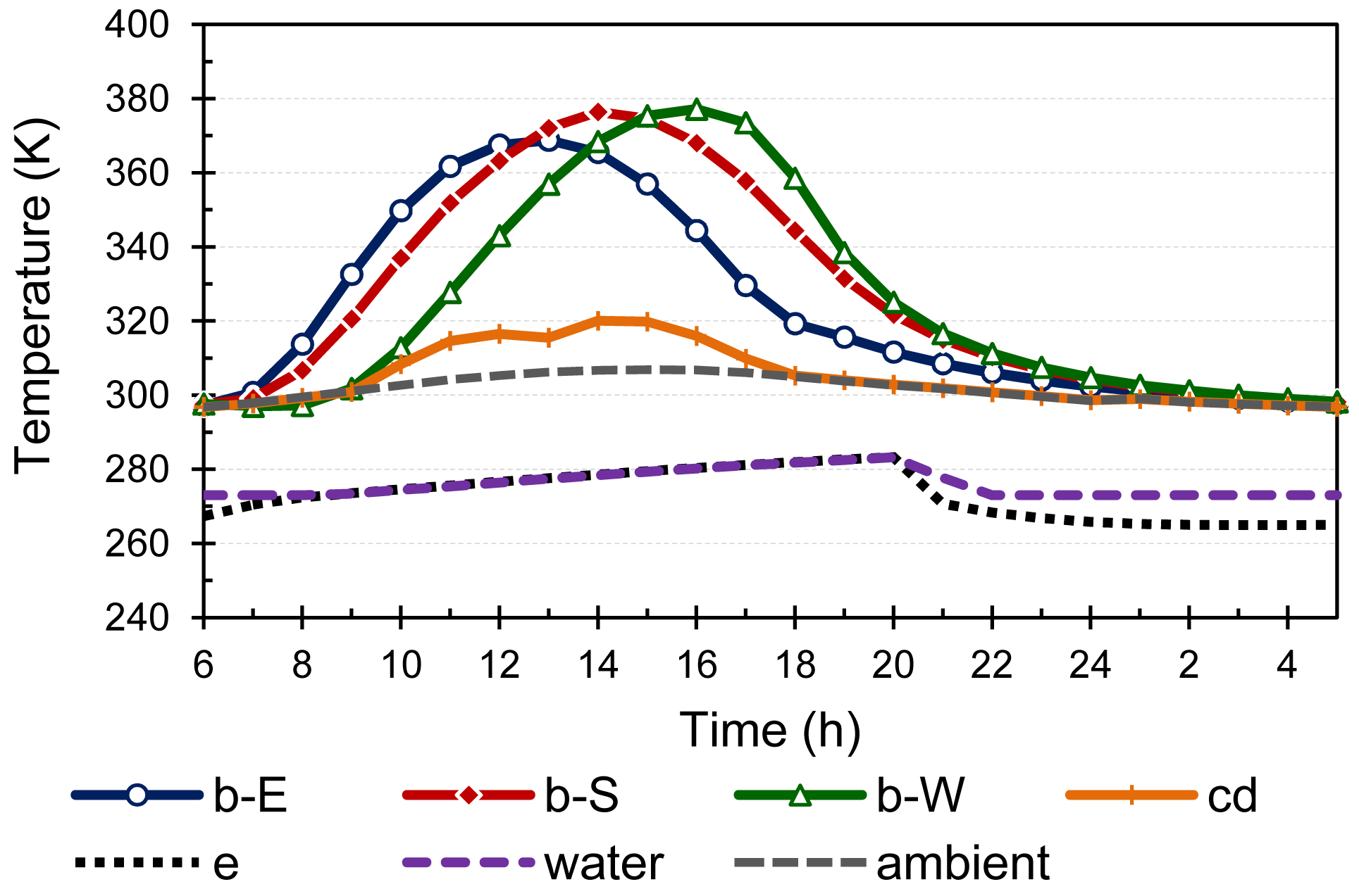
The temperatures of the main heat exchangers of the solar adsorption system are shown in Figure 8. The adsorbent bed temperature of each wing is following its absorber temperature. The condenser temperature increases in the day time and remains around 310 K to 320 K. Such a high temperature is because the naturally air cooled condenser was considered and ambient temperature was also relatively high. The condenser temperature again rises in the afternoon when the desorbed refrigerant starts coming from the west wing as indicated in Figure 8. During the late night the beds' temperature approaches the ambient temperature because the adsorption rate also becomes slow at that time. The investigated system operates intermittently, whereby cooling is produced only at night when the evaporator is connected with the adsorbing beds. Therefore, the evaporator and water temperatures increase during the day due to heat loss to the ambience. When the evaporator is connected with adsorbing beds at night, the evaporator temperature starts decreasing. It was set in the simulation model that when the evaporator and water temperatures became 0 °C or below then the water temperature remains constant, indicating the production of ice.
Figure 9 shows the concentration of the refrigerant in each bed. It can be noted that the desorption starts earlier in the east wing and ended soon too. This is because the east wing achieved the required temperature earlier due to its bending angle toward the east, and when the sun moves toward the west, the east wing losses its solar heat capturing efficiency that is needed to continue the desorption process. A similar behavior can be noted in west wing, but in the opposite order. In the west wing, desorption starts late but remains late into the afternoon hours. This shows the advantage of the proposed CPC with wings that the system can operate for a longer period of time compared to the conventional linear collector.
The amount of ice produced is shown in Figure 10. During the day no ice was produced because evaporator was not connected with the beds. The ice was produced during the night when the water temperature become 0 °C or below.
5.2. Effect of Length of Wings in Different Season
The performance of the solar adsorption refrigeration system with proposed wing type CPC was evaluated by changing the length of the wings and compared with the performance of the system when operated with a linear 3 m CPC. In each case the total length of the wing type CPC was kept constant to 3 m that was equal to a linear CPC. The lengths of the east and west wings were always kept equal, and the length of the south wing was calculated by subtracting the sum of the lengths of the east and west wings from the 3 m. The system was operated by valves that were controlled according to the conditions given in Table 2.
Figure 11 shows the effect of lengths of wings in Tokyo for different seasons of the year. It can be noticed that a wings lengths of 1.25 m shows the maximum performance in all seasons, except for August, where the maximum performance was found to be at 1.5 m length. It should also be noted that proposed CPC was optimized for year round operation. The performance of the collectors depends on the tilt and bending angle of the wings. In August, the optimum angle settings and weather data were favorable for the wings; therefore, the results show the maximum performance at 1.5 m wing length that indicates there was no south wing. The overall year round performance was found to be optimal at the east and west wing length of 1.25 m.
In Figure 12, the results of all seasons are combined. Here it can be seen that the SCE has highest values in the month of February. In our simulation, the actual weather data was used, and such high values in February are because the ambient conditions were favorable to desorb and adsorb more refrigerant due a high solar irradiance and low ambient temperature.
Figure 13 shows the comparison between the systems' performance with the proposed CPC at the optimal length of 1.25 m and with a linear CPC in terms of SCE. It can be noted that the performance increases up to 6% with the wing type CPC compared to the linear CPC in the month of August and increases by up to 1.42% in the month of February.
Similarly, the results were summarized for the ice production with the wing type CPC at 1.25 m wing length and compared with the ice production with a linear CPC for a whole year's season (Figure 14). Here again the wing type CPC produced a maximum 13% more ice in the month of August compared to the ice produced with linear CPC. The maximum amount of ice was produced in the month of February and almost all the water in the refrigerator was converted into ice. February is from the peak winter month in Tokyo and according to the actual data used, the ambient temperature were low, around 10 °C during the day and remained around 0 °C during night. Therefore, due to favorable conditions the maximum amount of ice was produced in the month of February.
6. Conclusions
In this study, a conventional intermittent solar adsorption refrigeration system with a wing type CPC proposed by the present authors was evaluated. The length of the proposed wing type CPC was the same as for a linear CPC, but it was divided into three parts. The ends were termed wings and were angled toward the east and west (surface azimuth angle) to capture the maximum solar energy during various times of the day. The proposed CPC was used at its optimum settings for tilt (35° for the south part and 45° for the east and west wings) and bending angles (0° for south part and 50° for east and west wings). A detailed dynamic simulation model was used to predict the system's behavior and performance. The actual weather data for Tokyo (Japan) were used in the simulation. The objectives of the study were to investigate the behavior of a conventional intermittent solar adsorption refrigeration system with the proposed wing type CPC, to investigate the effect of length of wings, and to compare the performance of the system with wing type and linear CPCs.
The results show that the performance of the system with wing type CPC is higher compared to the performance with a linear CPC. The optimum lengths of wings were found to be 1.25 m for the east and west wings. The performance increase up to 6% in the summer and up to 2% in the winter with the wings type CPC set at 1.25 m wings length. Similarly, the ice production increased up to 13% in summer with the proposed wing type CPC. The results indicate that the wing type CPC can continue the desorption process for a longer period of time. This advantage will be more effective for continuous solar driven systems.
In summary, it can be concluded that the proposed wing type collector increases the system performance compared to a linear collector with the same length. The system can be operated for a longer period of time with a wing type CPC without the need for tracking. In addition, the proposed wing type CPC is cost-effective compared to using an expensive tracking system or a heat storage tank that requires additional maintenance costs.
Conflicts of Interest
The authors declare no conflicts of interest.
References
- Asif, M. Sustainable energy options for Pakistan. Renew. Sustain. Energy Rev. 2009, 13, 903–909. [Google Scholar]
- Ozyurt, O.; Bakırcı, K.; Karslı, S.; Erdogan, S.; Yılmaz, M.; Comaklı, O. Energy production, consumption, and environmental pollution for sustainable development: A case study in Turkey. Renew. Sustain. Energy Rev. 2008, 12, 1529–1561. [Google Scholar]
- Solangi, K.H.; Islam, M.R.; Saidur, R.; Rahim, N.A.; Fayaz, H. A review on global solar energy policy. Renew. Sustain. Energy Rev. 2011, 15, 2149–2163. [Google Scholar]
- Saha, B.B.; El-Sharkawy, I.I.; Chakraborty, A.; Koyama, S.; Banker, N.D.; Dutta, P.; Prasad, M.; Srinivasan, K. Evaluation of minimum desorption temperatures of thermal compressors in adsorption refrigeration cycles. Int. J. Refrig. 2006, 29, 1175–1181. [Google Scholar]
- Sumathy, K.; Yeung, K.H.; Yong, L. Technology development in the solar adsorption refrigeration systems. Prog. Energy Combust. Sci. 2003, 29, 301–327. [Google Scholar]
- Umair, M.; Akisawa, A.; Ueda, Y. Optimum Settings for a Compound Parabolic Concentrator with Wings Providing Increased Duration of Effective Temperature for Solar-Driven Systems: A Case Study for Tokyo. Energies 2013, 7, 28–42. [Google Scholar]
- Anyanwu, E.E.; Ezekwe, C.I. Design, construction and test run of a solid adsorption solar refrigerator using activated carbon/methanol, as adsorbent/adsorbate pair. Energy Convers. Manag. 2003, 44, 2879–2892. [Google Scholar]
- Fan, Y.; Luo, L.; Souyri, B. Review of solar sorption refrigeration technologies: Development and applications. Renew. Sustain. Energy Rev. 2007, 11, 1758–1775. [Google Scholar]
- Lemmini, F.; Errougani, A. Building and experimentation of a solar powered adsorption refrigerator. Renew. Energy 2005, 30, 1989–2003. [Google Scholar]
- Louajari, M.; Mimet, A.; Ouammi, A. Study of the effect of finned tube adsorber on the performance of solar driven adsorption cooling machine using activated carbon–ammonia pair. Appl. Energy 2011, 88, 690–698. [Google Scholar]
- Fadar, A.E.; Mimet, A.; Pérez-García, M. Modelling and performance study of a continuous adsorption refrigeration system driven by parabolic trough solar collector. Sol. Energy 2009, 83, 850–861. [Google Scholar]
- Li, C.; Wang, R.Z.; Wang, L.W.; Li, T.X.; Chen, Y. Experimental study on an adsorption icemaker driven by parabolic trough solar collector. Renew. Energy 2013, 57, 223–233. [Google Scholar]
- González, M.I.; Rodríguez, L.R. Solar powered adsorption refrigerator with CPC collection system: Collector design and experimental test. Energy Convers. Manag. 2007, 48, 2587–2594. [Google Scholar]
- Headley, O.S.; Kothdiwala, A.F.; McDoom, I.A. Charcoal-methanol adsorption refrigerator powered by a compound parabolic concentrating solar collector. Sol. Energy 1994, 53, 191–197. [Google Scholar]
- Ibrahim, A.; Othman, M.Y.; Ruslan, M.H.; Mat, S.; Sopian, K. Recent advances in flat plate photovoltaic/thermal (PV/T) solar collectors. Renew. Sustain. Energy Rev. 2011, 15, 352–365. [Google Scholar]
- Choudhury, B.; Saha, B.B.; Chatterjee, P.K.; Sarkar, J.P. An overview of developments in adsorption refrigeration systems towards a sustainable way of cooling. Appl. Energy 2013, 104, 554–567. [Google Scholar]
- Yeh, H.-M.; Ho, C.-D. Collector Efficiency in Downward-Type Internal-Recycle Solar Air Heaters with Attached Fins. Energies 2013, 6, 5130–5144. [Google Scholar]
- Kalogirou, S.A. Solar thermal collectors and applications. Prog. Energy Combust. Sci. 2004, 30, 231–295. [Google Scholar]
- El-Sharkawy, I.I.; Saha, B.B.; Koyama, S.; He, J.; Ng, K.C.; Yap, C. Experimental investigation on activated carbon–ethanol pair for solar powered adsorption cooling applications. Int. J. Refrig. 2008, 31, 1407–1413. [Google Scholar]
- Duffie, J.A.; William, A.B. Solar Engineering of Thermal Processes, 2nd ed.; John Willy & Sons: New York, NY, USA, 1991. [Google Scholar]
- Tchinda, R. Thermal behaviour of solar air heater with compound parabolic concentrator. Energy Convers. Manag. 2008, 49, 529–540. [Google Scholar]
- Saha, B.B.; El-Sharkawy, I.I.; Chakraborty, A.; Koyama, S. Study on an activated carbon fiber–ethanol adsorption chiller: Part I—System description and modelling. Int. J. Refrig. 2007, 30, 86–95. [Google Scholar]
- Vasta, S.; Maggio, G.; Santori, G.; Freni, A.; Polonara, F.; Restuccia, G. An adsorptive solar ice-maker dynamic simulation for north Mediterranean climate. Energy Convers. Manag. 2008, 49, 3025–3035. [Google Scholar]
- Rahman, A.; Ueda, Y.; Akisawa, A.; Miyazaki, T.; Saha, B. Design and Performance of an Innovative Four-Bed, Three-Stage Adsorption Cycle. Energies 2013, 6, 1365–1384. [Google Scholar]
- Henke, S.; Kadlec, P.; Bubník, Z. Physico-chemical properties of ethanol—Compilation of existing data. J. Food Eng. 2010, 99, 497–504. [Google Scholar]
Nomenclature
| A | Area (m2) |
| Cp | Specific heat (J·kg−1·K−1) |
| CPC | Compound parabolic concentrator |
| D | Exponential constant (K−2) |
| Dso | Pre-exponential constant (m2 s−1) |
| Ea | Activation energy (J kg−1) |
| hcc | Overall heat transfer coefficient from condenser to ambient (W m−2 K−1) |
| hRr | Radiation heat transfer coefficient between the receiver and the cover (W·m−2·K−1) |
| hRs | Radiation heat transfer coefficient between the cover and the sky (W·m−2·K−1) |
| hrc | Convective heat transfer coefficient between the cover and the receiver (W·m−2·K−1) |
| hca | Convective heat transfer coefficient from the cover due to wind (W·m−2·K−1) |
| ΔHst | Heat of adsorption/desorption (J kg−1) |
| I | Solar radiation (W·m−2) |
| LH | Latent heat of vaporization (J kg−1) |
| M | Mass (kg) |
| Ps | Saturation pressure (Pa) |
| Q | Energy absorbed (W) |
| q | Instantaneous uptake (kg kg−1) |
| R | Refrigerant gas constant |
| SCE | Specific cooling effect (kJ kg−1 of adsorbent) |
| T | Temperature (K) |
| Ub | Overall heat transfer coefficient between receiver and adsorbent bed (W m−2 K−1) |
| Ue | Overall heat transfer coefficient between evaporator and ambient (W m−2 K−1) |
| Uw | Overall heat transfer coefficient between evaporator and water tank (W m−2 K−1) |
| Uβ | Overall heat transfer coefficient between water tank and ambient (W m−2 K−1) |
| W* | Uptake of refrigerant (kg kg−1) |
| W0 | Width of absorber (m) |
| Superscript | |
|---|---|
| a | Adsorption |
| d | Desorption |
| nr | Average number of reflections |
| Subscripts | |
|---|---|
| ab | Absorber |
| ACF | Activated carbon fiber |
| air | Air |
| ap | Aperture |
| b | Bed |
| bm | Beam |
| c | CPC cover |
| cd | Condenser |
| cpc | CPC |
| Cu | Copper |
| diff | Diffuse |
| E | East wing of the CPC |
| e | Evaporator |
| ice | Ice |
| re | Refrigirant (ethanol) |
| S | South part of the CPC |
| sky | Sky |
| W | West wing of the CPC |
| w | Water |
| wt | Water tank |
| Greek Letters | |
|---|---|
| γ | Surface azimuth/bending angle (°) |
| θi | Angle of incidence (°) |
| θcpc | Half acceptance angle (°) |
| θz | Zenith angle (°) |
| β | Tilt angle (°) |
| γs | Solar azimuth angle (°) |
| α | Absorptance |
| ρ | Reflectance |
| τ | Transmittance |


| Parameter | Value | Unit |
|---|---|---|
| Adsorption Isotherm | ||
| D | 1.716 × 10⁻⁶ | K−2 |
| Dso | 1.8 × 10⁻¹² | m2 s−1 |
| Ea | 306.7 × 10³ | J kg−1 |
| R | 180.5 | J kg−1 |
| Rp | 6.5 × 10⁻⁶ | m |
| Wo | 0.707 | kg kg−1 |
| CPC characteristics for each wing | ||
| Aap | changing | m2 |
| Aab | 0.098 | m2 |
| Lcpc,E | changing | m |
| Lcpc,W | Lcpc,E | m |
| Lcpc,S | 3 − (Lcpc,E + Lcpc,W) | m |
| nr | 0.68 | - |
| ρcpc | 0.92 | - |
| τcpc | (ρcpc)nr | - |
| τdiff | τcpc | - |
| Cover | ||
| Ac | changing | m2 |
| Cpc | 840 | J kg−1 |
| Mc | 0.9 | kg |
| αc | 0.05 | - |
| τc | 0.89 | - |
| Absorber | ||
| CpCu | 386 | J kg−1 K−1 |
| Mab | 5 | kg |
| Ub | 25 | W m−2 K−1 |
| αab | 0.95 | - |
| ρab | 0.15 | - |
| Adsorbent beds | ||
| CpACF | 941 | J kg−1 K−1 |
| Cpre | 2400 | J kg−1 K−1 |
| ΔHst | 1.2 × 10⁶ | J kg−1 |
| MACF | 3 | kg/unit Lcpc |
| Condenser | ||
| Acd | 0.4 | m2 |
| hcc | 15 | W m−2 K−1 |
| LH,re | 8.46 × 10⁵ | J kg−1 |
| Mcd | 2 | kg |
| Mre-cd | 1 | kg |
| Refrigerator | ||
| Ae | 0.86 | m2 |
| Awt | 0.37 | m2 |
| Cpw | 4200 | J kg−1 K−1 |
| LH,w | 2.5 × 10⁶ | J kg−1 |
| Me | 4 | kg |
| Ue | 0.6 | W m−2 K−1 |
| Uw | 5 | W m−2 K−1 |
| Uβ | 0.2 | W m−2 K−1 |
| Process | Valve timing | System status | Remarks |
|---|---|---|---|
| Pre-heating | Sunrise–9 am | Adsorbent beds were isolated from condenser & evaporator: Pc = Ps(Tcd) | - |
| Desorption | 9 am–sunset | The wing in which the desorption start was connected with condenser: Pc = Ps(Tcd) | Each wing was controlled separately. It was connected with condenser when the desorption starts and disconnect when desorption reaches to minimum level. |
| Pre-cooling | Sunset–9 pm | Adsorbent beds were isolated from condenser & evaporator: Pc = Ps(Tcd) | - |
| Adsorption | 9 pm–sunrise | Adsorbent beds were connected with evaporator: Pe = Ps(Te) | - |
© 2014 by the authors; licensee MDPI, Basel, Switzerland. This article is an open access article distributed under the terms and conditions of the Creative Commons Attribution license ( http://creativecommons.org/licenses/by/3.0/).
Share and Cite
Umair, M.; Akisawa, A.; Ueda, Y. Performance Evaluation of a Solar Adsorption Refrigeration System with a Wing Type Compound Parabolic Concentrator. Energies 2014, 7, 1448-1466. https://doi.org/10.3390/en7031448
Umair M, Akisawa A, Ueda Y. Performance Evaluation of a Solar Adsorption Refrigeration System with a Wing Type Compound Parabolic Concentrator. Energies. 2014; 7(3):1448-1466. https://doi.org/10.3390/en7031448
Chicago/Turabian StyleUmair, Muhammad, Atsushi Akisawa, and Yuki Ueda. 2014. "Performance Evaluation of a Solar Adsorption Refrigeration System with a Wing Type Compound Parabolic Concentrator" Energies 7, no. 3: 1448-1466. https://doi.org/10.3390/en7031448
APA StyleUmair, M., Akisawa, A., & Ueda, Y. (2014). Performance Evaluation of a Solar Adsorption Refrigeration System with a Wing Type Compound Parabolic Concentrator. Energies, 7(3), 1448-1466. https://doi.org/10.3390/en7031448