Mathematical Modeling Analysis and Optimization of Key Design Parameters of Proton-Conductive Solid Oxide Fuel Cells

Abstract
: A proton-conductive solid oxide fuel cell (H-SOFC) has the advantage of operating at higher temperatures than a PEM fuel cell, but at lower temperatures than a SOFC. This study proposes a mathematical model for an H-SOFC in order to simulate the performance and optimize the flow channel designs. The model analyzes the average mass transfer and species' concentrations in flow channels, which allows the determination of an average concentration polarization in anode and cathode gas channels, the proton conductivity of electrolyte membranes, as well as the activation polarization. An electrical circuit for the current and proton conduction is applied to analyze the ohmic losses from an anode current collector to a cathode current collector. The model uses relatively less amount of computational time to find the V-I curve of the fuel cell, and thus it can be applied to compute a large amount of cases with different flow channel dimensions and operating parameters for optimization. The modeling simulation results agreed satisfactorily with the experimental results from literature. Simulation results showed that a relatively small total width of flow channel and rib, together with a small ratio of the rib's width versus the total width, are preferable for obtaining high power densities and thus high efficiency.1. Introduction
Having an electrolyte conductive to oxide ions, a solid oxide fuel cell (O-SOFC) works at relatively high operating temperatures, which helps to maintain a low activation polarization and eliminate the use of expensive catalysts in a fuel cell [1]. However, high operating temperatures also result in disadvantages including potential thermal fatigue/failure of the cell material and gas sealing, as well as the thermal stress in the ceramic cell components [2]. With the solid oxide electrolyte being conductive to protons, a proton-conductive solid oxide fuel cell (H-SOFC) works at a relatively lower temperature [3] than a regular SOFC. A lower operation temperature helps to alleviate the problems of thermal stress and thermal expansion mismatch related to high operating temperatures in a regular SOFC. An H-SOFC also allows more utilization of the fuel (H2) and thus a better efficiency than a regular SOFC [4].
A number of research efforts have been devoted to experimental studies on proton conductive solid oxide fuel cells. Some of them focused on property of materials used for H-SOFC. For the key component material of an H-SOFC, Zhao et al. studied the performance of H-SOFC using BaCe0.7In0.3−xYxO3−δ as the electrolyte material [5]. Ling et al. studied the fuel cell performance using a stable La2Ce2O7 as the electrolyte material [6]. Guo et al. studied the performance of a carbon dioxide-tolerant proton-conducting solid oxide fuel cell with a dual-layer electrolyte [7]. H-SOFC was also tested using BaZr0.8In0.2O3−δ as the proton-conductive electrolyte [8]. For electrode materials, Lin et al. evaluated the performance of H-SOFC using BaCo0.7Fe0.2Nb0.1O3−δ (BCFN) as the cathode material [9]. Deng et al. investigated fuel cell performance using a cathode made of the material of PrBa0.5Sr0.5Co2O5−δ [10]. Zhao et al. studied the performance of a cobalt-free proton-conductive oxide fuel cell performance using Ba0.5Sr0.5Fe0.8Cu0.2O3−δ as cathode material [11]. For fabrication related issues, Tsai et al. studied the tortuosity in electrodes materials in an anode-supported H-SOFC [12].
While the materials of the H-SOFC component are very important, a good design and management of the flow field is also very helpful to a better performance of the fuel cells. The current work presents studies and design optimization of a H-SOFC via modeling and simulation analysis. The modeling will give an easy-to-approach and comprehensive analysis to the mass transfer, activation and ohmic polarizations, and can predict the fuel cell performance and thus optimize the flow channel designs [13]. The simulation results are to be compared with the experimental results obtained from literature to validate the model. The power density and voltage output due to the optimization of the dimensions of flow channels and ribs will be presented.
2. Basic Aspects of an H-SOFC
A proton conducting solid oxide fuel cell consists of a metal oxide electrolyte sandwiched between two electrodes. Fuel is supplied on the anode side which is oxidized into protons in an electrochemical reaction as:
This produces electrons which move towards cathode via an external circuit driven by the potential difference between the two electrodes. The fuel consumption leads to concentration gradient of hydrogen (if fuel is a mixture) in anode and therefore feed to the anode-electrolyte interface by permeation [14]. In cathode, air is supplied, which offers oxygen to react with the receiving electrons and protons from anode to form water from the following electrochemical reaction:
The anode material and catalyst are required to be highly active to improve the H-SOFC performance. These days, mixtures of nickel oxide and electrolyte are used as anode support materials [15]. Nickel behaves like a catalyst which increases the rate of chemical reaction and oxidizes the fuel at the interface. The anode reaction occurs at the interface of anode and electrolyte. Together with the reactant phase, the anode and electrolyte forms the so-called triple phase boundary. Mixtures of NiO and electrolyte increase the triple phase boundary. Electrolyte material behaves like a proton conductor which conducts protons and transfers it across electrolyte layer. Good proton conductivity is important to the increase of the rate of the overall reaction [16]. The electrolyte must be as thin as possible and have low activation energy. The perovskite structured compound (ABO3 specially AZrO3) family are considered especially good electrolyte materials. An ideal cathode material must be chemically non-reactive with the electrolyte. A cathode material must be porous with high oxygen permeability. Due to these reasons novel perovskite oxide materials are chosen as cathode. Recently, Ba0.5Sr0.5Zn0.2Fe0.8O3−δ (BSZF) has been developed as a novel cobalt free oxygen permeable membrane with high permeation behavior and good chemical stability at high temperatures [17].
Different from an oxide-ion conductive SOFC, H-SOFCs have the electromotive force expressed as:
Due to its high operation temperature, the water in H-SOFC is in vapor state and is assumed as an ideal gas, the same as other gas species.
3. Numerical Modeling to H-SOFC
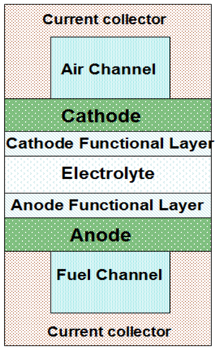
Figure 1 shows the schematic of the typical elements/components of an H-SOFC, which includes the electrolyte, electrode components, flow channels, as well as the flow channel walls also acting also as local current collectors. BaCe0.9Y0.1O2.95 (BCY) and BaCe0.5Zr0.3Y0.16Zn0.04 O3−δ (BCZYZn) are used as electrolytes for the current mathematic model [15,17]. The anode material is NiO which has a substrate of NiO-BCY and NiO-BCZYZn. The cathode materials are Ba0.5Sr0.5Zn0.2Fe0.8O3−δ (BSZF) and Ba0.5Sr0.5Co0.8Fe0.2O3−δ (BSCF). The electrode and electrolyte materials properties used for the simulation are presented in Tables 1 and 2. The contact resistances between current collector and electrodes vary with operation temperatures, which are given in Table 3. Fuel was supplied on the anode side, and cathode was fed with air for the needed oxygen. The utilization of fuel and oxygen are 85% and 50%, respectively, and a unit length of 1.0 m of the channel length (normal to the paper in Figure 1) is considered in the modeling. Setting the utilization percentage of fuel and oxygen being constant, the flow rates of fuel and air vary with the current density.
To obtain the electromotive force, the partial pressures of species during an electrochemical reaction are needed. The partial pressure of a species is proportional to its molar fraction in a mixture. Therefore, the mass transfer processes of species from bulk flow to the reaction site (the electrode and electrolyte interface) have to be analyzed.
3.1. Mass Transfer Analysis
3.1.1. Anode Side Mass Transfer Analysis
The convective mass transfer flow rate of hydrogen from bulk flow to the surface of anode is expressed in Equation (4). The consumed hydrogen flow rate ṅ equals to the current divided by 2F, where F is the Faraday constant.
The mass diffusion for hydrogen and vapor in porous electrodes are analyzed by calculating the mass transfer flow rate as given in Equations (5) and (6). For all the analyses, the mass fluxes from surfaces toward the bulk flow are designated to be positive.
In the fuel channel, the hydrogen is consumed and protons conduct through the electrolyte to form water with oxygen on the cathode side. Therefore, there is no water vapor flux on anode, which gives JH2O = 0. The effective diffusivity of hydrogen-water system comprises of Knudsen and ordinary diffusion.
The total wall flow velocity due to mass transfer is directly related to summation of mass flux of all species and the total density at wall. Therefore, there is.
This is a basic equation describing mass transfer boundary conditions [19]. Substituting diffusion velocity υa back to Equations (5) and (6) and introducing the new effective diffusivities for hydrogen and vapor as given by Equations (11) and (12), we could obtain compact expression for mass flux as given by Equations (13) and (14).
Given the molar consumption fluxes of hydrogen and water to left-hand sides of the above equations and considering the hydrogen molar concentration difference from the bulk flow to the anode surface, the concentration difference of hydrogen through the porous layer is given in Equation (15). Correspondingly, the concentration difference of water is given in Equation (16).
To consider the mass diffusion resistance in anode functional layer, we can simply add the mass transfer resistance term of the functional layer, , to the parenthesis on the left-hand side of Equations (15) and (16). Here δaf is the thickness of the anode functional layer. The equation for Daf_H2(eff) is in the same form as that of Equation (11). However, the parameters used for calculating Daf_H2(eff) are from anode functional layer. Equations for mass fluxes for water vapor in the functional layer are similar to those in the anode layer, which are not presented here.
From the above analysis, it is clear that with the given current density and the concentration of species in the bulk flow, one can obtain the species concentration at the anode/electrolyte interface.
3.1.2. Cathode Side Mass Transfer Analysis
On the cathode side, there are three species, O2, N2 and H2O involved in the mass transfer. Similar to the anode side, the same analysis should be applied to the cathode side to find out the concentration of O2, N2 and H2O at electrolyte/cathode interface. The molar consumption rate of O2 is known as the total current divided by 4F, where F is the Faraday's constant. Analogous to mass transfer, the mass transfer flux of oxygen from bulk flow to the cathode surface is similar to that of hydrogen at the anode side.
The mass transfer of oxygen, nitrogen and water in porous cathode layer are described using the following equations.
The effective diffusivities of species in mixture are given in Equations (21)–(23).
The ordinary diffusivity of one species in a mixture of more than two species is given by Equation (24).
Here, cathode side effective diffusivities for three of the species are given in Equations (25)–(27). These diffusivities are used for cathode species' mass transfer, given by Equations (28)–(30) after substituting cathode velocity to the mass flux equations.
To consider the oxygen mass diffusion resistance in cathode functional layer, a new term, Rcfl, given in Equation (31) is introduced as follows, which can be added to the left-hand side of Equation (28) for cathode functional layer.
From the above analysis, it is clear that at any given current density, the molar concentrations of all species at the electrode/electrolyte can be obtained. Finally, the partial pressures of all species are related to the molar concentration in the following forms:
3.2. Irreversible Voltage/Potential Losses
3.2.1. Activation Polarization
The activation polarization is given by the Butler-Volmer equation [20], as given in Equation (37), where J_current is the current density, J0 is the exchange current density, α is the transfer coefficient which is typically set as 0.5, z is the number of electrons passed through the external circuit for every mole of fuel oxidation. For H-SOFC, the value of z is 2. Therefore, the activation polarization could be expressed in terms of current density J, as shown in Equation (38).
The exchange current density is related to material property and operation conditions (porosity, pore size, temperature and pressure). According to literature [20], exchange current density for O-SOFC is expressed in terms of the effect of both micro structural properties and operating condition as given in Equations (39) and (40). In Equations (39) and (40), Eact,a (=1.0 × 10⁵ J/mol) and Eact,c (=1.2 × 10⁵ J/mol) are activation energy levels at anode and cathode, respectively; Y is the ratio of grain contact neck to the grain size and n is the porosity of electrodes; Dp and Ds represent the pore size and grain size; ka and kc are adjustable coefficients, which are reported as ka of 6.634 × 10⁻⁸ and kc of 7.534 × 10⁻⁸ in reference [20]. Here we assume that Equations (39) and (40) are applicable for H-SOFC as well as O-SFOC.
3.2.2. Ohmic Loss
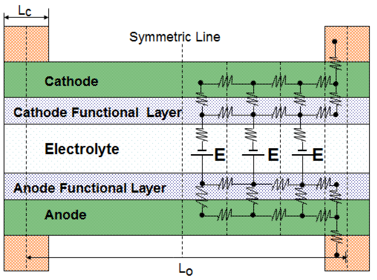
The flow of electrons and ions in fuel cell components results in ohmic polarization due to ohmic resistance in all the layers as well as electrical contact resistance [21] between layers. In order to have a precise ohmic loss analysis, an equivalent electrical circuit for a flow channel and its two walls (local current collectors) was constructed as shown in Figure 2. There are five layers in the electrode assembly. Electrode layers for both anode and cathode are porous material for reactants to diffuse through. Another layer is functional layer where electrochemical reaction takes place. Having functional layer is the recent technology that can enhance the electrochemical reaction by creating more morphological contact between electrode material and electrolyte material. The temperature of functional layer is slight higher than other layers due to exothermic reaction. The current conduction route from a typical anode-side current collector to a cathode-side current collector can be discretized into multiple segments. With the symmetric discretization of the flow channel, computational time for the circuit can be significantly reduced. The electrical potentials at all the nodes are calculated using Kirchhoff's current law, which states that the summation of current flow into the node should be zero. A similar method has been applied to calculate the ohmic loss in PEM fuel cells and O-SOFC [22–24].
The electromotive force shown in the equivalent circuit should be obtained from Equation (3) which also subtracts the activation polarizations of both anode and cathode. The species partial pressures obtained from the mass transfer analysis are used in Equation (3).
3.3. Computational Procedures
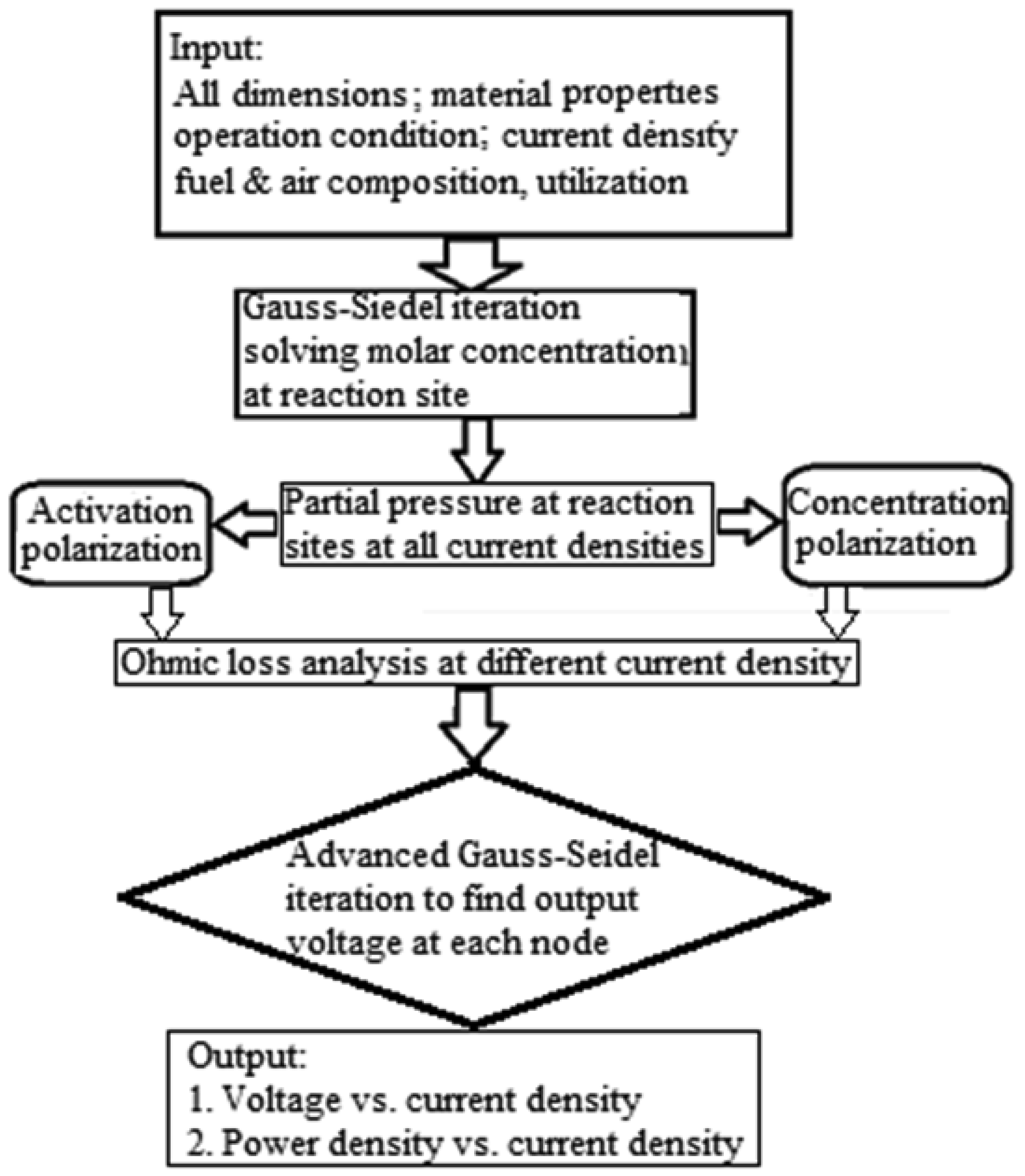
The numerical calculation follows a particular procedure, which is outlined as a flow chart in Figure 3. First, all the physical properties and dimensions of the fuel cell are defined. With the known amount of reactants as well as the prescribed current density, the values of concentrations of species at intermediate layers were calculated through iterations of the equations for the mass transfer, which consequently converges. Using these values of concentration, the partial pressures of all species can be calculated which thus considers the concentration polarization in the electromotive force as given in Equation (3). The electrical circuit was then analyzed for ohmic losses by discretizing the single channel fuel cell structure with multiple nodes. The electromotive force shown in the electrical circuit is the value from Equation (3) subtracted with the activation polarization. The activation polarization was considered through Volmer-Butler's equation. From the solution of electrical circuit, the fuel cell voltage is obtained with the given current density and other conditions. Multiple calculations are conducted for a specific temperature and a range of current densities for the V-i curve. The power output from the fuel cell is easily obtained as the product of cell voltage and current, and therefore, the power density versus current density is also obtained for the fuel cell.
4. Results and Discussion
4.1. Validation to the Modeling
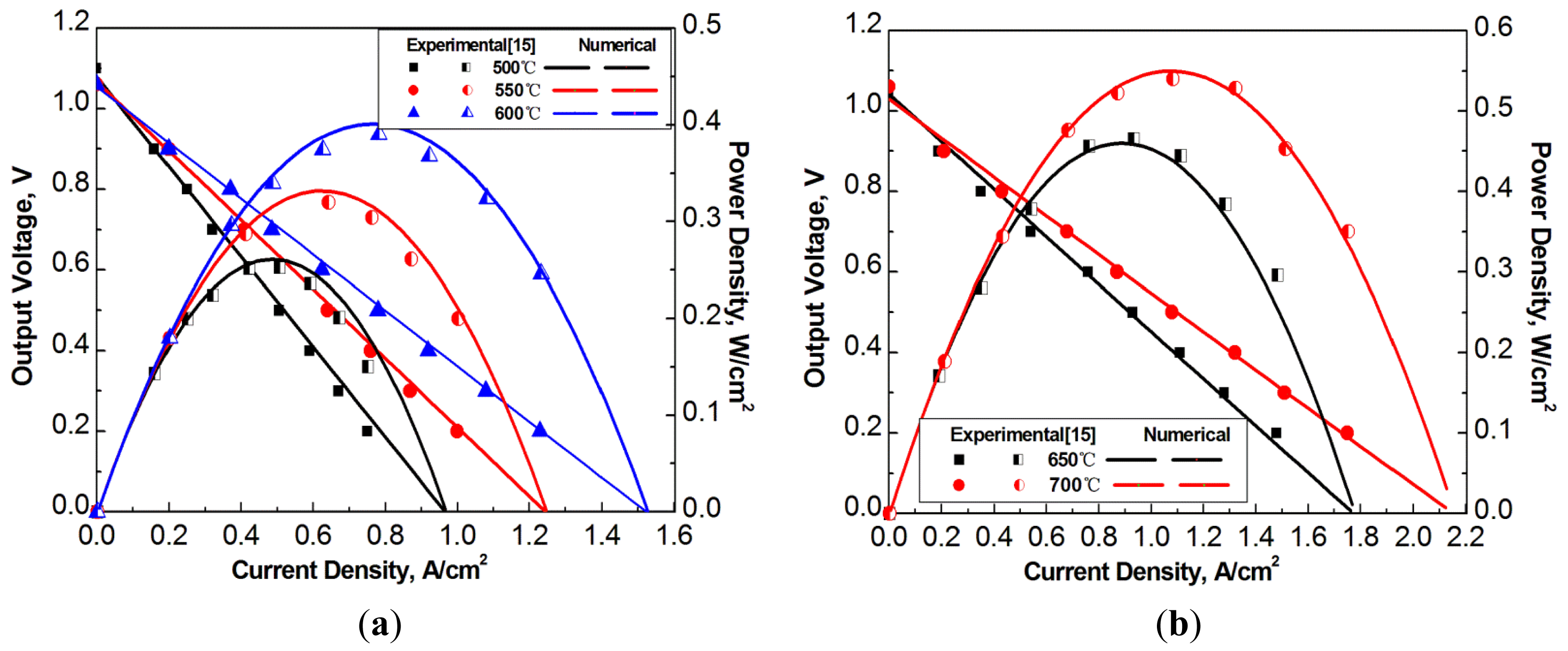
The analytical modeling is validated by comparing the simulation results with experimental data in literature. The cited experimental results are from references [15]. The studies in the reference reported operation temperatures of the H-SOFC up to 700 °C.
Material properties of the H-SOFC from reference [15] are listed in Tables 4 and 5, which were used in the modeling simulation. The tortuosities used for simulation are properly assumed for H-SOFC electrodes. The conductivity of electrode changes with temperature insignificantly compared to that of electrolyte, therefore, it is treated as a constant, as given in Table 5. Current simulation model has a flow channels with width of 1.2 mm and rib width 0.6 mm for both anode and cathode channels. The present simulation results of V-I curves are compared with the experimental results from reference [15], as given in Figure 4. The simulation results agree with the experimental data very well, which indicates the validity of the model as well as the related physical properties of the fuel cell components from the literature. The contact resistances at interface at different operation temperatures are shown in Table 3.
The comparison of the modeling results with experimental data from references has evident that the currently developed H-SOFC model is effective and reliable. In the following section the model will be used to optimize the geometrical designs of the flow channels in H-SOFC.
4.2. Optimization of the Dimensions of Flow Channels and Walls of an H-SOFC
A quite number of researchers have reported studies to flow channel and flow field designs, which have been recognized to affect the fuel cell performance in both PEM fuel cells [25] and SOFCs. For PEM fuel cells, it is widely known that serpentine flow channels are known as the “industry standard” due to the better performance compared to that of many other different designs [26]. Serpentine flow channels are commonly adopted in PEM fuel cells [22]. In the present work, serpentine flow channels are considered in the modeling and simulation. The dimensions of flow channels that affect the H-SOFC performance will be optimized. The material property of electrode and electrolyte from Tables 1–3 are used for the simulation.
Two important parameters, the total width Lo, which includes the width of the flow channel and the width of one of the channel walls, and the ratio of the rib's width versus the total width, are to be optimized for the serpentine flow channels. The rib width is designated as Lc and the channel width is Lo−Lc, as seen in Figure 2. The rib ratio RLc is then given as:
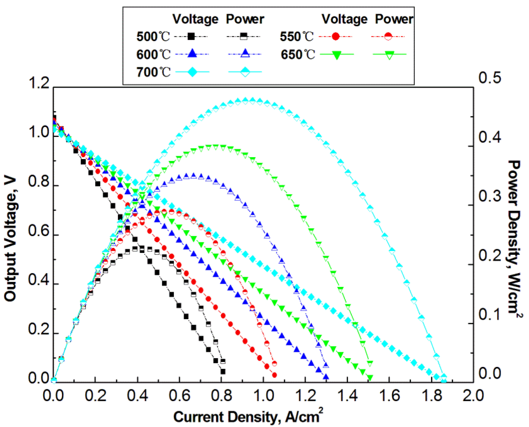
Before the optimization to the flow channel designs, the effect of the operating temperature is studied, and an operating temperature is selected for the optimization of the dimensions of the channels. For this study, the total width is 3 mm and the rib ratio RLc is 0.3. The operation temperature ranges from 500 °C to 700 °C. As seen in Figure 5 the output power density increases with the increase of temperature, which is the same phenomenon as was shown in the model validation simulations and experimental data from literature. High operation temperature makes it possible to have greater reaction kinetics and greater proton conductivity, and also a reduced contact resistance between electrode and current collector, which thus results in higher output voltage.
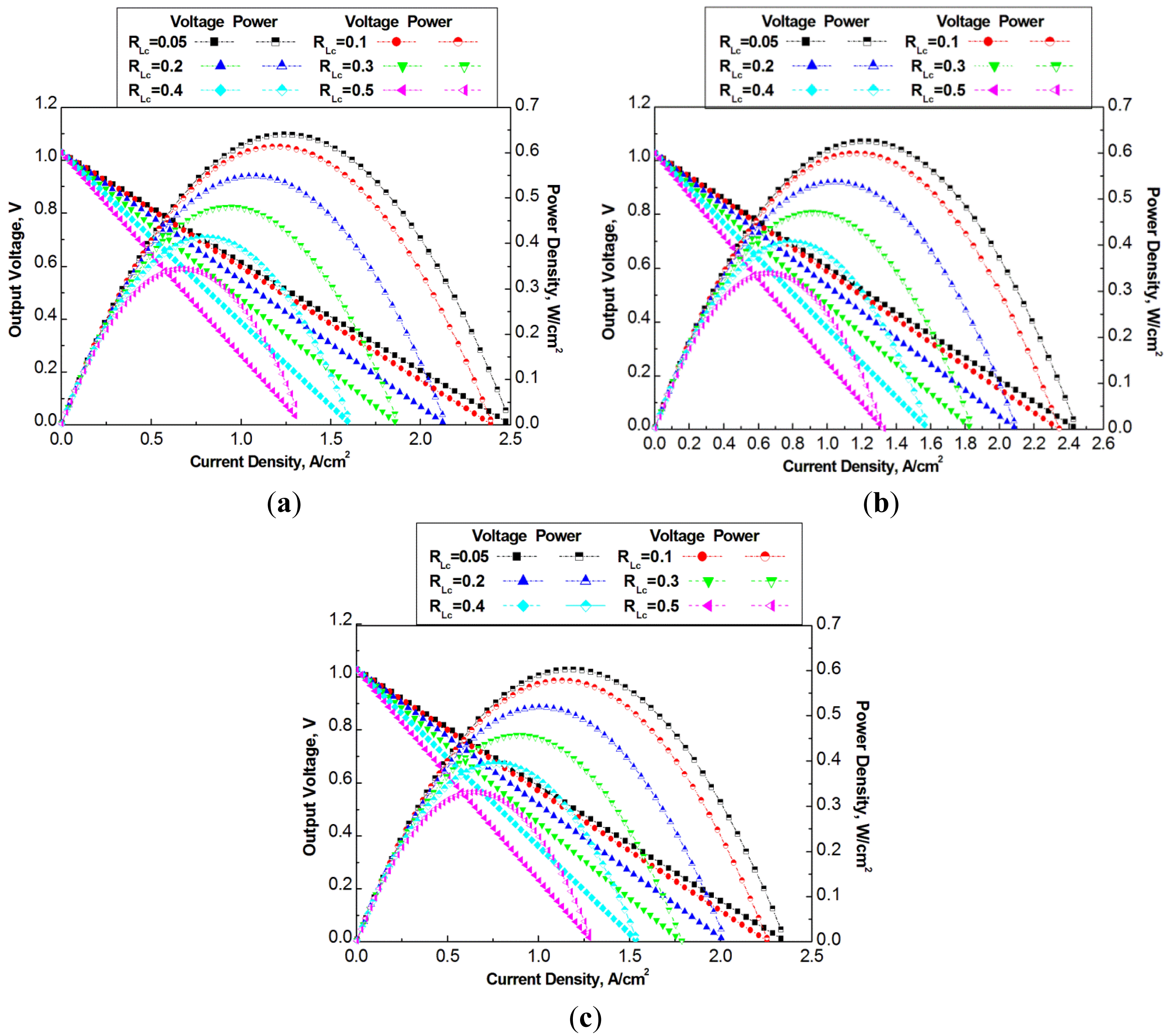
The flow channel geometry optimization simulation is conducted under operation temperature of 700 °C which allows it to achieve high power density among the simulated temperatures. Three groups of dimensions of channels are selected for optimization design, which have total width Lo in 2 mm, 4 mm, and 6 mm, respectively. In each group of dimensions, five rib ratios are selected. Figure 6 presents the power density versus current density of the three groups of cells.
Figure 6a–c show a common characteristics that the cell power output increases with the decrease of the rib ratio for the studied cases under a constant total channel width Lo. The maximum output power density in Figure 6a is around 0.64 W/cm2 at a rib ratio of RLc = 0.05, which is 70% greater than the case with a rib ratio of RLc = 0.5. Obviously, the smaller rib ratio means more opening area of electrochemical reactions, and therefore, the fuel cell power density increases. On the other hand, with more and more decrease of the rib ratio the increase of the fuel cell power density becomes less significant, which implies that too small rib ratio should not be selected. A small width of the rib also means high contact resistance. It can also be difficult to fabricate the flow channels with very small walls.
At larger total widths, Lo = 4 mm, and 6 mm, the decrease of the rib ratio also results in the increase of the fuel cell power density. However, the maximum power densities from the three cases of different total widths are different. With smaller total width, the maximum power density is higher than that with larger total width. The maximum power density in Figure 6a–c is 0.64 W/cm2, 0.6 W/cm2 and 0.58 W/cm2, respectively.
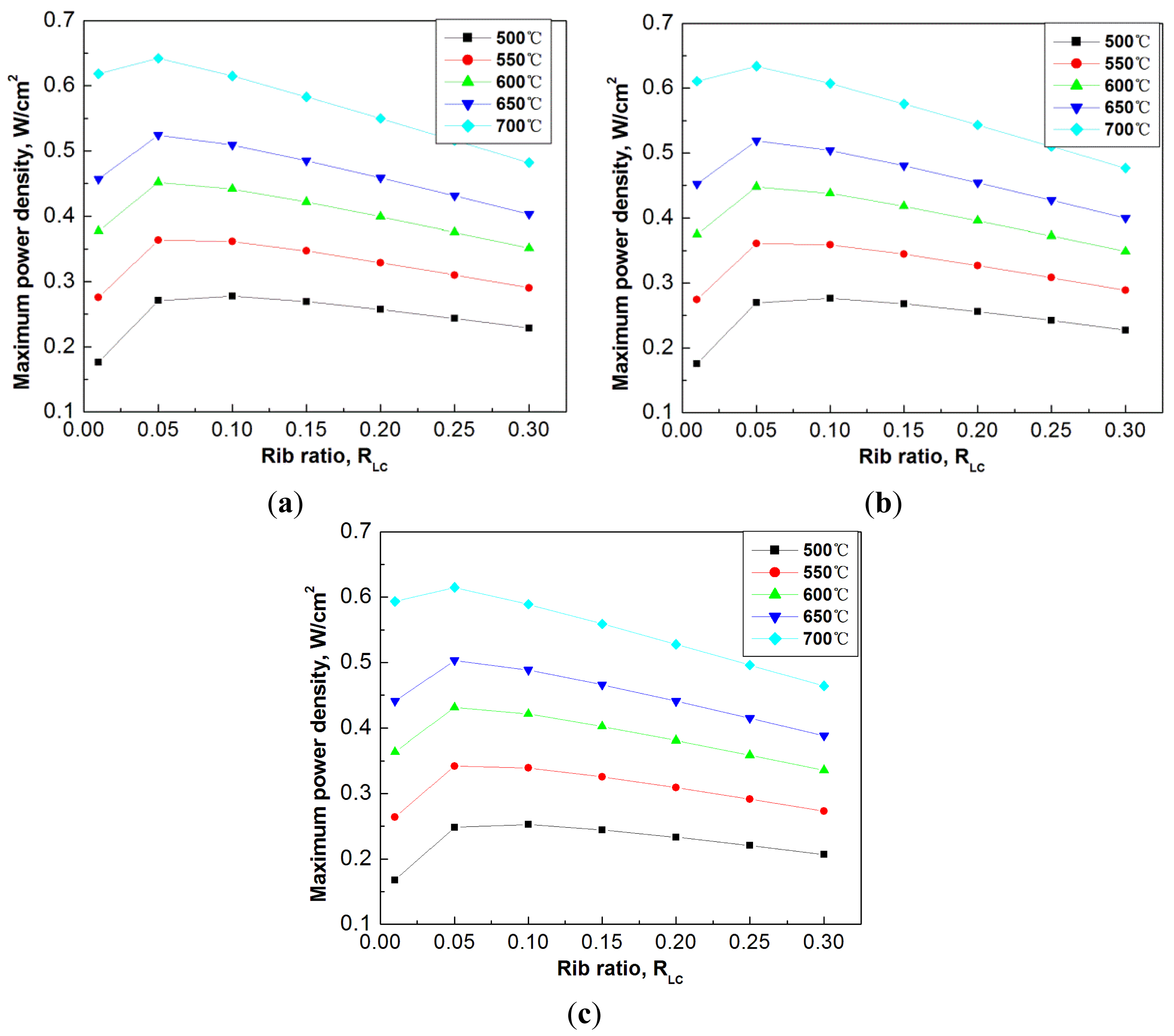
To have an overview of the optimization of flow channels, Figure 7 shows the effect of rib ratio to the maximum power density at different operation temperatures, ranging from 500 °C to 700 °C. The selected another three cases of channel total widths are 1.5 mm, 3.0 mm, and 4.5 mm. The rib ratio in each case varies from 0.01 to 0.3.
It is seen from Figure 7 that at all the studied temperatures, the decrease of the rib ratio is preferable, which results in the increase of the maximum power density. At different operation temperatures, the optimum rib ratio can be slightly different. For example, at temperature of 500 °C, the optimum rib ratio is around 0.1, while at temperature of 700 °C the optimum rib ratio is smaller. Nevertheless, nearly one optimum rib ratio can be largely applicable to all the different operation temperatures, for example, a rib ratio of 0.05, in all the studied cases.
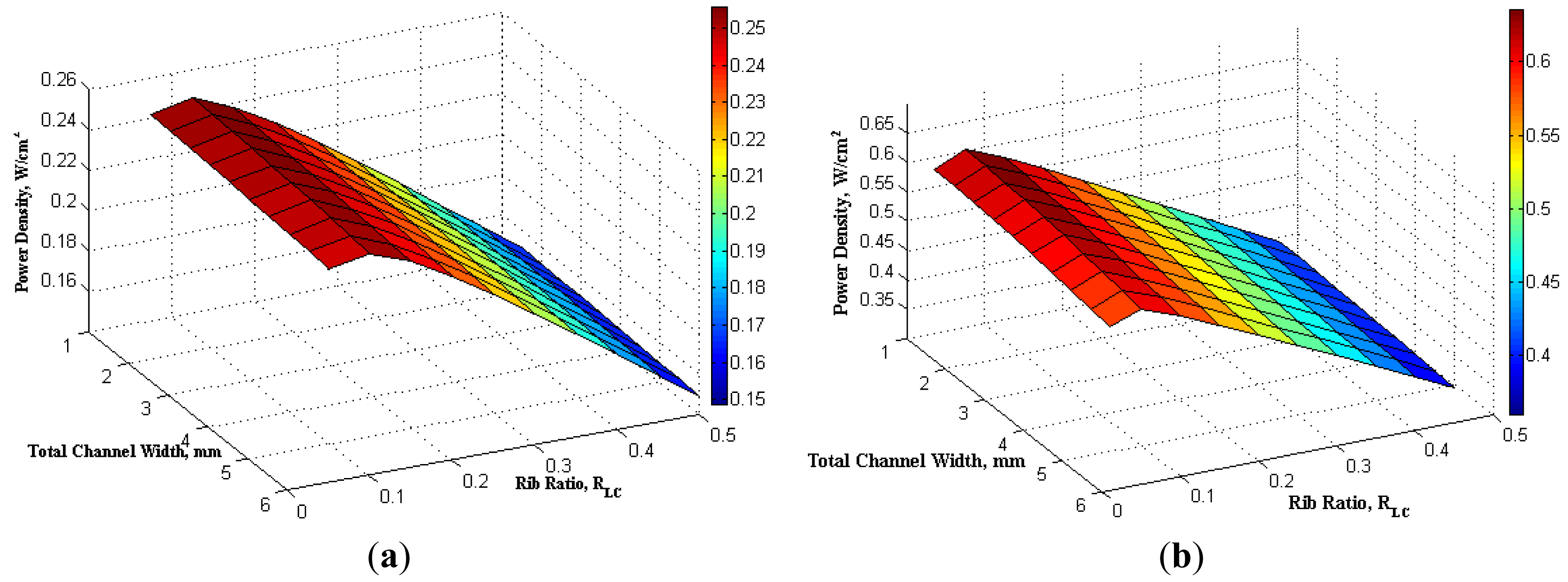
To show the overview of the effect of both the total width Lo and the rib ratio RLc, Figure 8 presents a contour of the maximum power density as a function of the total width and rib ratio. It is clear that the peak of the maximum power density locates at the coordinate of both small total width and small rib ratio. For a fixed total width (summation of channel width and rib width), the increase of RLc means that channel rib area increases which will tend to improve the current collection efficiency. However, increase of RLc results in the decrease of channel flow area, which does not benefit to improvement of the cell power density. This is because that decrease of channel area will decrease the exposure of reactants to electrode layer and reduce the diffusion and reaction, which will result in the drop of power density. It is also found that the maximum power density from fuel cells is more sensitive to the variation of the rib ratio rather than the total channel width. The channel and rib width affect the performance of proton conducting SOFCs and it also has effect on conventional SOFCs and other type of fuel cells [13].
5. Conclusions
An analytical model was developed for an H-SOFC in order to study the fuel cell performance and also to optimize the flow channel designs. This is a one-dimensional model that was validated by experimental data from the literature and was used to simulate and optimize the flow channel dimensions, mainly two important parameters—the total width of flow channel with channel rib/wall and the ratio of the channel rib/wall to the total width.
It was found from the optimization study that the fuel cell maximum power density can be higher if one chooses a smaller total width as well as a smaller ratio of the width of channel rib/wall against the total width. However, this ratio has an optimum point, too small a value can also result in decrease of the maximum power density. To show this feature, a contour of the maximum power density as a function of the total width and the rib ratio is provided in the paper.
The optimum ratio of channel rib/wall versus the total width varies slightly with the difference of the operation temperature. Nevertheless, nearly one optimum rib ratio can be largely applicable to all the different operation temperatures.
Acknowledgments
The support from the Office of Naval Research of the USA and the University of Tennessee SimCenter under the contract #8500011366 is gratefully acknowledged.
Conflicts of interest
The authors declare no conflict of interest.
References
- Ni, M.; Leung, D.Y.C.; Leung, M.K.H. Mathematical modeling of ammonia-fed solid oxide fuel cells with different electrolytes. Int. J. Hydrog. Energy 2008, 33, 5765–5772. [Google Scholar]
- Hajimolana, S.A.; Hussain, M.A.; Ashri Wan Daud, W.M.; Soroushb, M.; Shamiri, A. Mathematical modeling of solid oxide fuel cells: A review. Renew. Sustain. Energy Rev. 2011, 15, 1893–1917. [Google Scholar]
- Iwahara, H. Proton conducting ceramics and their applications. Solid State Ion. 1996, 86–88, 9–15. [Google Scholar]
- Pen, R.; Wu, Y.; Yang, L.; Mao, Z. Electrochemical properties of intermediate-temperature SOFCs based on proton conducting Sm-doped BaceO3 electrolyte thin film. Solid State Ion. 2005, 177, 389–390. [Google Scholar]
- Zhao, F.; Chen, F. Performance of solid oxide fuel cells based on proton-conducting BaCe0.7In0.3−xYxO3−δ electrolyte. Int. J. Hydrog. Energy 2010, 35, 11194–11199. [Google Scholar]
- Ling, Y.; Chen, J.; Wang, Z.; Xia, C.; Peng, R.; Lu, Y. New ionic diffusion strategy to fabricate proton-conducting solid oxide fuel cells based on a stable La2Ce2O7 electrolyte. Int. J. Hydrog. Energy 2013, 38, 7430–7434. [Google Scholar]
- Guo, Y.; Ran, R.; Shao, Z. Fabrication and performance of a carbon dioxide-tolerant proton-conducting solid oxide fuel cells with a dual-layer electrolyte. Int. J. Hydrog. Energy 2010, 35, 10513–10521. [Google Scholar]
- Sun, W.; Zhu, Z.; Shi, Z.; Liu, W. Chemically stable and easily sintered high temperature proton conductor BaZr0.8In0.2O3−δ for solid oxide fuel cells. J. Power Source 2013, 229, 95–101. [Google Scholar]
- Lin, Y.; Zhou, W.; Sunarso, J.; Ran, R.; Shao, Z. Characterization and evaluation of BaCo0.7Fe0.2Nb0.1O3−δ as a cathode for proton-conducting solid oxide fuel cells. Int. J. Hydrog. Energy 2012, 37, 484–497. [Google Scholar]
- Ding, H.; Xue, X. Proton conducting solid oxide fuel cells with layered PrBa0.5Sr0.5Co2O5−δ perovskite cathode. Int. J. Hydrog. Energy 2010, 35, 2486–2490. [Google Scholar]
- Zhao, L.; He, B.; Ling, Y.; Xun, Z.; Peng, R.; Meng, G.; Liu, X. Cobalt-free oxide Ba0.5Sr0.5Fe0.8Cu0.2O3−δ for proton-conducting solid oxide fuel cell cathode. Int. J. Hydrog. Energy 2010, 35, 3769–3774. [Google Scholar]
- Tsai, C.-L.; Schmidt, V.H. Tortuosity in anode-supported proton conductive solid oxide fuel cell found from current flin rates and dusty-gas model. J. Power Sources 2011, 196, 692–699. [Google Scholar]
- Li, P.W.; Kotwal, A.; Sepulveda, J.L.; Loutfy, R.O.; Chang, S. An easy-to-approach and comprehensive model for planar type SOFCs. Int. J. Hydrog. Energy 2009, 34, 6393–6406. [Google Scholar]
- Ni, M.; Leung, M.K.H.; Leung, D.Y.C. Mathematical modeling of proton-conducting solid oxide fuel cells and comparison with oxygen-ion-conducting counterpart. Fuel Cells 2007, 7, 269–278. [Google Scholar]
- Lin, Y.; Ran, R.; Zheng, Y. Evaluation of Ba0.5Sr0.5Co0.8Fe0.2O3−δ as a potential cathode for an anode-supported proton-conducting solid-oxide fuel cell. J. Power Sources 2008, 180, 15–22. [Google Scholar]
- Deng, X.; Petric, A. Geometrical modeling of the triple-phase-boundary in solid oxide fuel cells. J. Power Sources 2005, 140, 297–303. [Google Scholar]
- Lin, B.; Hu, M.; Ma, J.; Jiang, Y.; Tao, S.; Meng, G. Stable, easily sintered BaCe0.5Zr0.3Y0.16Zn0.04O3−δ electrolyte-based protonic ceramic membrane fuel cells with Ba0.5Sr0.5Zn0.2Fe0.8O3−δ perovskite cathode. J. Power Sources 2008, 183, 479–484. [Google Scholar]
- Fuller, E.N.; Schettler, P.D.; Giddings, J.C. New methods for prediction of binary gas-phase diffusion coefficients. Ind. Eng. Chem. Res. 1966, 58, 18–27. [Google Scholar]
- Loius, C. Burmeister Convection Heat Transfer, 2nd ed.; John Wiley & Sons, Inc.: New York, NY, USA, 1993; Chapter 2; pp. 38–39. [Google Scholar]
- Ni, M.; Leung, M.K.H.; Leung, D.Y.C. Parametric study of solid oxide fuel cell performance. Energy Convers. Manag. 2007, 48, 1525–1535. [Google Scholar]
- Kraytsberg, A.; Auinat, M.; Ein-Eli, Y. Reduced contact resistance of PEM fuel cell's bipolar plates via surface texturing. J. Power Sources 2007, 164, 697–703. [Google Scholar]
- Liu, H.; Li, P.; Wang, K. Optimization of PEM fuel cell flow channel dimensions—Mathematic modeling analysis and experimental verification. Int. J. Hydrog. Energy 2013, 38, 9835–9846. [Google Scholar]
- Li, P.; Ki, J.-P.; Liu, H. Analysis and optimization of current collecting systems in PEM fuel cells. Int. J. Energy Environ. Eng. 2012, 3, 1–10. [Google Scholar]
- Li, P.; Tao, G.; Liu, H. Effect of the geometries of current collectors on the power density in a solid oxide fuel cell. Int. J. Energy Environ. Eng. 2011, 2, 1–11. [Google Scholar]
- Aiyejina, A.; Sastry, M.K.S. PEMFC flow channel geometry optimization: A review. J. Fuel Cell Sci. Technol. 2012, 9, 011011:1–011011:24. [Google Scholar]
- Li, X.; Sbir, I.; Park, J. A flow channel design procedure for PEM fuel cells with effective water removal. J. Power Sources 2007, 163, 933–942. [Google Scholar]
Nomenclature
| A | Mass transfer area of cross section (m2) |
| C | Species molar concentration (mol/m3) |
| D(eff) | Effective diffusivity (m2/s) |
| Di,k | Knudsen diffusivity (i—species) (m2/s) |
| Di,j | Ordinary diffusivity (i and j—species) (m2/s) |
| Dp | Pore size (μm) |
| Ds | Grain size (μm) |
| E | Electromotive force from the Nernst Equation (V) |
| Eact,a | Activation energy level at the anode side (J/mol) |
| Eact,c | Activation energy level at the cathode side (J/mol) |
| F | Faraday's constant 96,485.3 (C/mol) |
| h | Convective mass transfer coefficient m/s |
| H-SOFC | Proton conducting Solid Oxide Fuel Cell |
| i | Current Density A/m2 |
| J | Species molar flux (mol/s) |
| Jo | Exchange current density (A/m3) |
| J-current | Current density |
| M | Molar mass kg/mol |
| ṅ | Molar consumption rate mol/s |
| p | Partial pressure |
| R | Gas constant 8.314 (J/mol/K) |
| re | Average pore radius of the electrodes (μm) |
| T | Temperature (K) |
| v | Velocity (m/s) |
| X | Mole fraction |
| Y | Ratio of grain contact neck to the grain size |
| Greek Symbols | |
|---|---|
| τ | Tortuosity |
| ε | Porosity |
| δ | Electrode thickness (m) |
| α | Transfer coefficient |
| Subscripts and Superscripts | |
|---|---|
| int | Interface (electrode-functional layer) |
| conc | Concentration polarization |
| c | Cathode |
| a | Anode |
| af | Anode functional layer |
| cf | Cathode functional layer |
| H2 | Hydrogen |
| O2 | Oxygen |
| N2 | Nitrogen |
| S | Surface |
| ∞ | Bulk flow |


| Properties | Anode | Cathode | Anode functional layer | Cathode functional layer |
|---|---|---|---|---|
| Pore Radius ×10−6 (m) | 2 | 2 | 2 | 2 |
| Porosity | 0.48 | 0.48 | 0.48 | 0.48 |
| Tortuosity | 3 | 3 | 3 | 3 |
| Thickness ×10−4 (m) | 6 | 0.2 | 0.2 | 0.1 |
| Temperature (°C) | 500 | 550 | 600 | 650 | 700 |
|---|---|---|---|---|---|
| Proton conductivity (S/m) | 0.6 | 0.77 | 0.95 | 1.12 | 1.38 |
Note: Electrolyte has a thickness of 5 × 10⁻⁵ (m).
| Temperature (°C) | 500 | 550 | 600 | 650 | 700 |
|---|---|---|---|---|---|
| Contact Resistivity(×10−7 Ω/m2) | 3.8 | 1.73 | 0.95 | 0.6 | 0.2 |
| Material | Thickness | Tortuosity | Porosity | Pore diameter | Grain size |
|---|---|---|---|---|---|
| Anode (NiO + BCY) | 600 μm | 3 | 48% | 1–2 μm | 2 μm |
| Electrolyte (BCY) | 50 μm | 3 | <3% | - | 2 μm |
| Cathode (BSCF) | 20 μm | 3 | 48% | 1–2 μm | 2 μm |
| Operating Temperatures(°C) | Anodeconductivity(S/cm) | Electrolyte Conductivity(S/m) | Cathode Conductivity(S/cm) |
|---|---|---|---|
| 500 | 1400 | 0.67 | 1100 |
| 550 | 1400 | 0.77 | 1100 |
| 600 | 1400 | 0.95 | 1100 |
| 650 | 1400 | 1.12 | 1100 |
| 700 | 1400 | 1.38 | 1100 |
© 2014 by the authors; licensee MDPI, Basel, Switzerland This article is an open access article distributed under the terms and conditions of the Creative Commons Attribution license ( http://creativecommons.org/licenses/by/3.0/).
Share and Cite
Liu, H.; Akhtar, Z.; Li, P.; Wang, K. Mathematical Modeling Analysis and Optimization of Key Design Parameters of Proton-Conductive Solid Oxide Fuel Cells. Energies 2014, 7, 173-190. https://doi.org/10.3390/en7010173
Liu H, Akhtar Z, Li P, Wang K. Mathematical Modeling Analysis and Optimization of Key Design Parameters of Proton-Conductive Solid Oxide Fuel Cells. Energies. 2014; 7(1):173-190. https://doi.org/10.3390/en7010173
Chicago/Turabian StyleLiu, Hong, Zoheb Akhtar, Peiwen Li, and Kai Wang. 2014. "Mathematical Modeling Analysis and Optimization of Key Design Parameters of Proton-Conductive Solid Oxide Fuel Cells" Energies 7, no. 1: 173-190. https://doi.org/10.3390/en7010173
APA StyleLiu, H., Akhtar, Z., Li, P., & Wang, K. (2014). Mathematical Modeling Analysis and Optimization of Key Design Parameters of Proton-Conductive Solid Oxide Fuel Cells. Energies, 7(1), 173-190. https://doi.org/10.3390/en7010173