Experimental Analysis of Wireless Power Transmission with Spiral Resonators


Abstract
:
1. Introduction
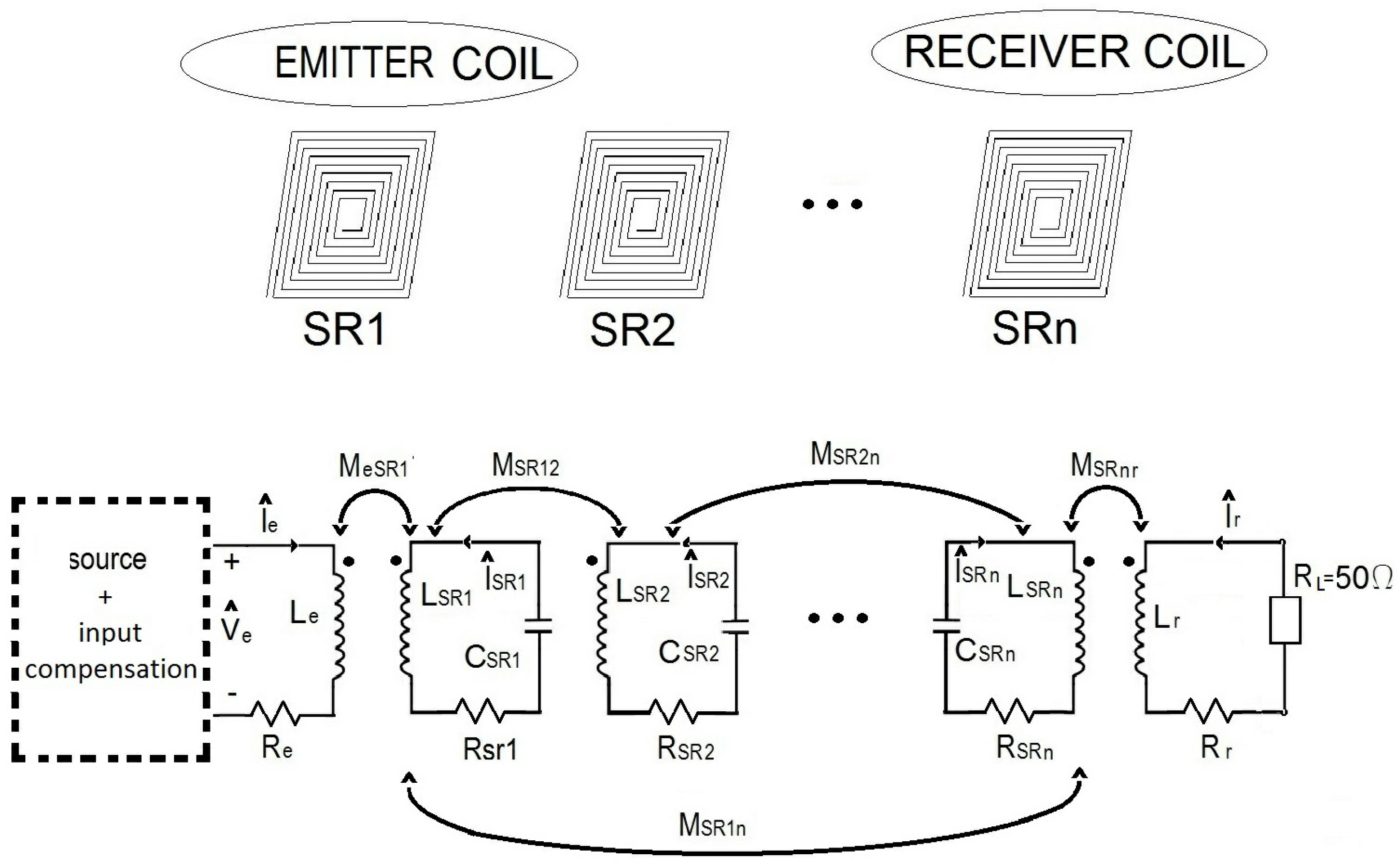
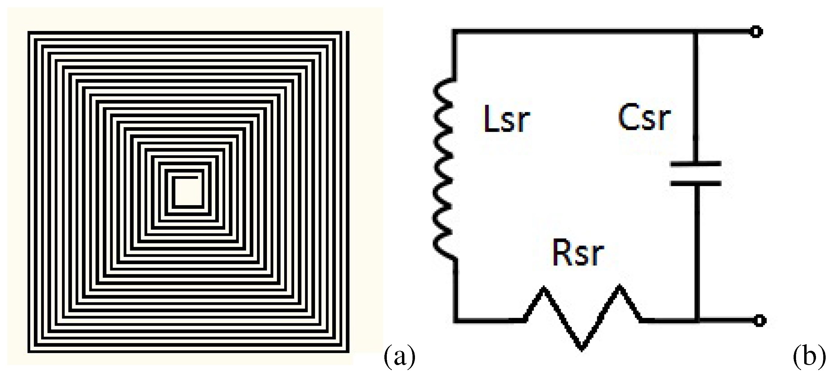
2. Design of SR and Equivalent Circuit

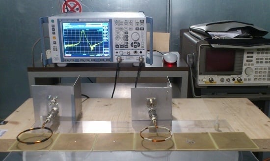
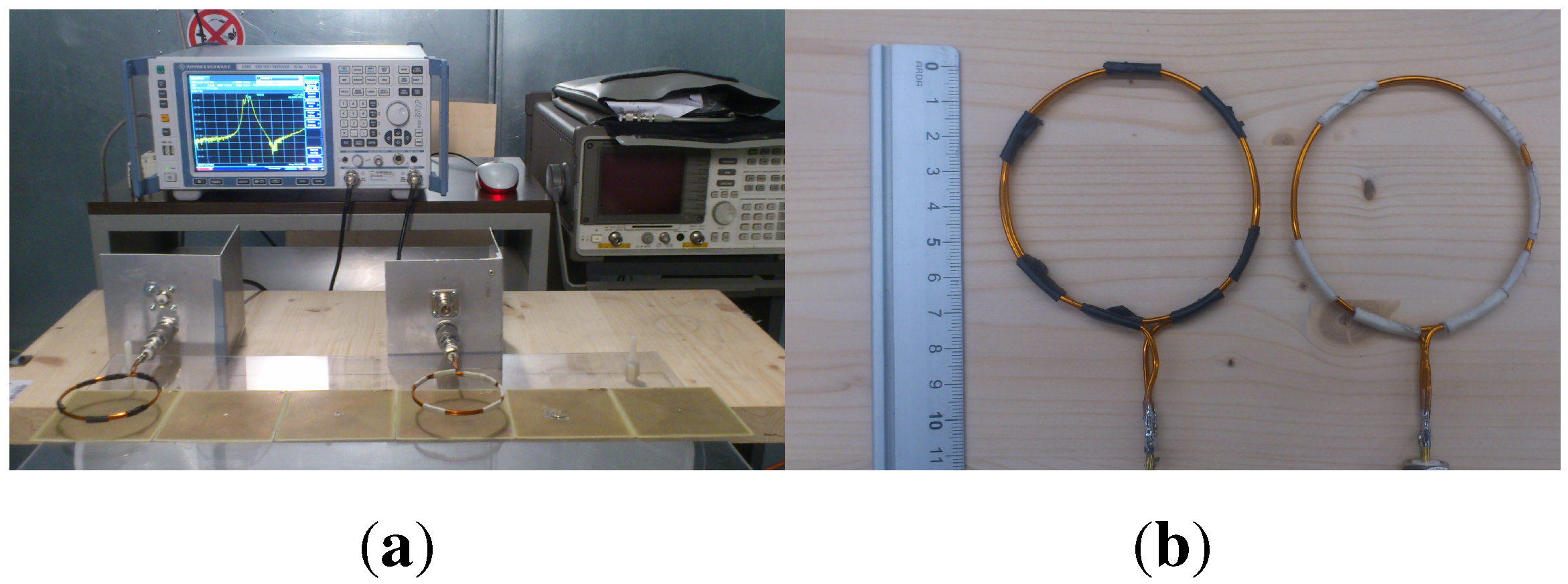
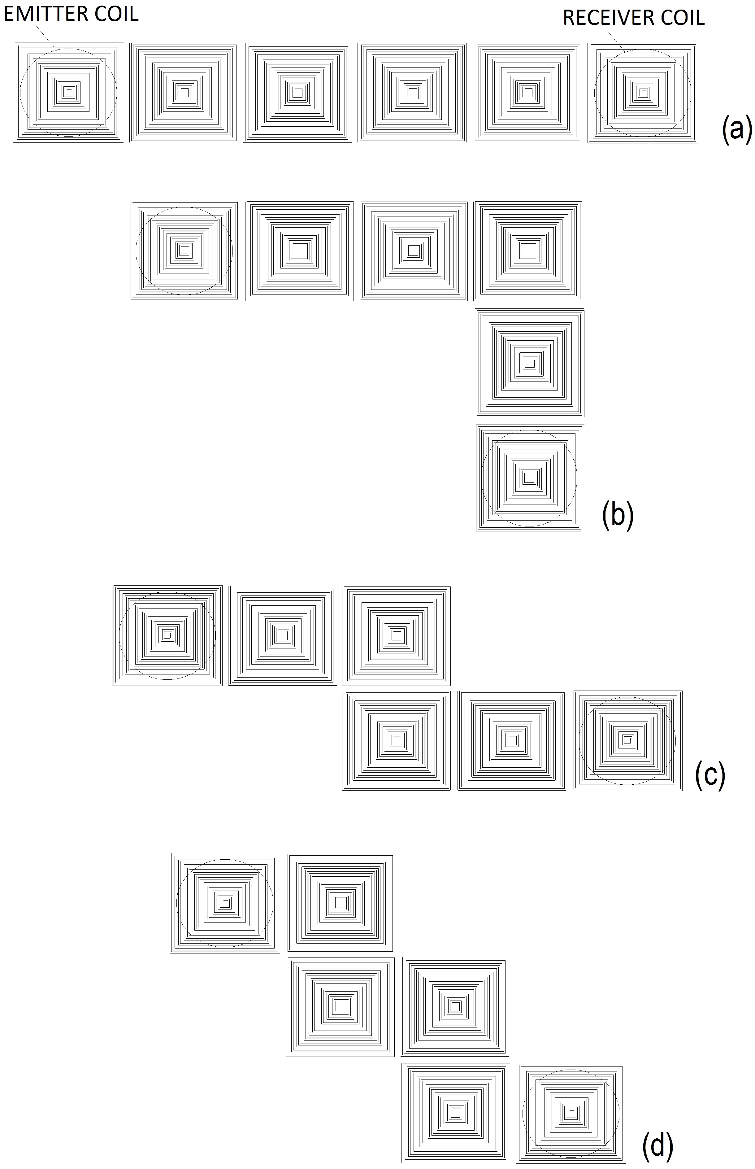
3. Experimental Setup


| Sample | [MHz] | [pF] |
|---|---|---|
| SR1 | 19.55 | 2.28 |
| SR2 | 19.56 | 2.28 |
| SR3 | 19.52 | 2.29 |
| SR4 | 19.52 | 2.29 |
| SR5 | 19.52 | 2.29 |
| SR6 | 19.3 | 2.34 |

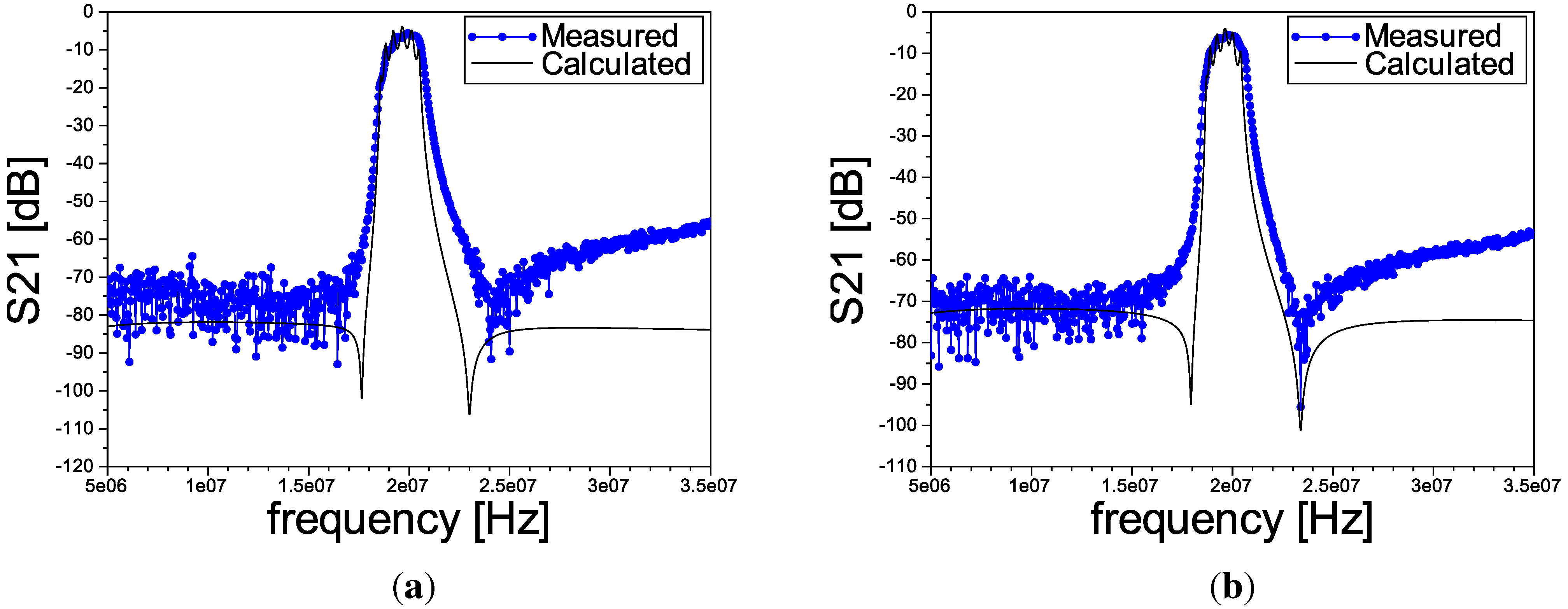
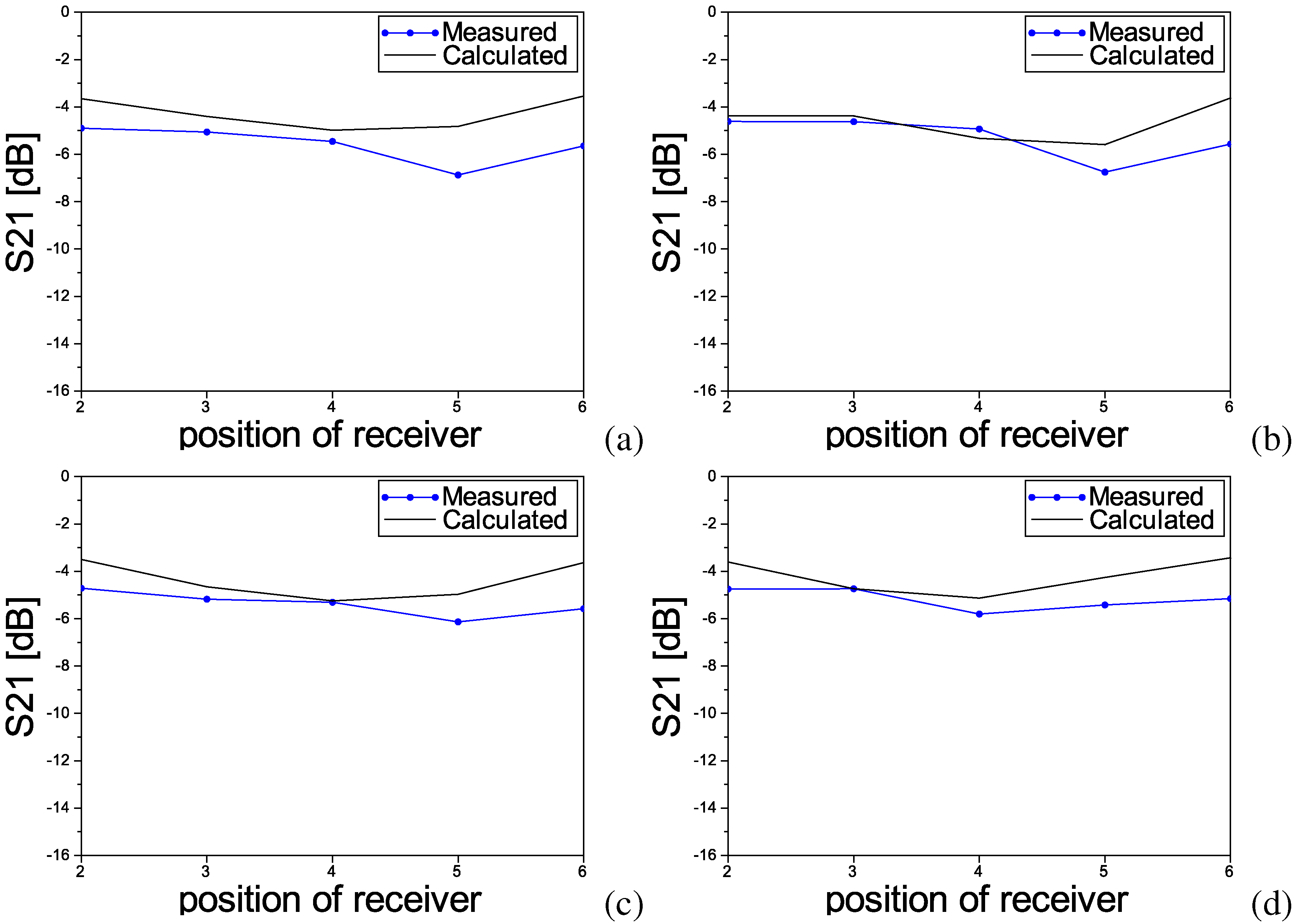
4. Results
| Receiver | I | II | III | IV | ||||
|---|---|---|---|---|---|---|---|---|
| SR2 | 19.4 | 20.7 | 19.3 | 20 | 19.3 | 20 | 19.3 | 20 |
| SR3 | 19.9 | 19.7 | 19.8 | 19.7 | 19.8 | 19.7 | 19.7 | 19.6 |
| SR4 | 19.7 | 20.5 | 19.4 | 20.6 | 19.6 | 19.2 | 19.3 | 19 |
| SR5 | 19.3 | 20.2 | 19.3 | 20.2 | 20.2 | 20.1 | 20.2 | 19 |
| SR6 | 20 | 19.6 | 19.8 | 19.6 | 19.9 | 19.6 | 19.8 | 19.5 |
5. Conclusions
Conflicts of Interest
References
- Villa, J.L.; Sallan, J.; Llombart, A.; Sanz, J.F. Design of a high frequency inductively coupled power transfer system for electric vehicle battery charge. Appl. Energy 2009, 86, 355–363. [Google Scholar] [CrossRef]
- Jang, Y.; Jovanovic, M. A contactless electrical energy transmission system for portable telephone battery chargers. IEEE Trans. Ind. Electron. 2003, 50, 520–527. [Google Scholar] [CrossRef]
- Wang, B.; Ellstein, D.; Teo, K.H. Analysis on Wireless Power Transfer to Moving Devices Based on Array of Resonators. In Proceedings of the European Conference Antennas and Propagation (EUCAP), Prague, Czech Republic, 26–30 March 2012.
- Choi, J.; Seo, C. High-efficiency wireless energy transmission using magnetic resonance based on metamaterial with relative permeability equal to −1. Prog. Electromagn. Res. 2010, 106, 33–46. [Google Scholar] [CrossRef]
- Wang, B.; Yerazunis, W.; Teo, K.H. Wireless power transfer: Metamaterials and array of coupled resonators. IEEE Proc. 2013, 101, 1359–1368. [Google Scholar] [CrossRef]
- Stevens, C.J. Power Transfer via metamaterials. CMC: Comput. Mater. Cont. 2013, 33, 1–18. [Google Scholar]
- Shamonina, E.; Kalinin, V.A.; Ringhofer, K.H.; Solymar, L. Magneto-inductive waveguide. Electron. Lett. 2002, 38, 371–373. [Google Scholar] [CrossRef]
- Stevens, C.J.; Chan, C.W.T.; Stamatis, K.; Edwards, D.J. Magnetic metamaterials as 1-D data transfer channels: An application for magneto-inductive waves. IEEE Trans. Microw. Theory Tech. 2010, 58, 1248–1256. [Google Scholar] [CrossRef]
- Radkovskaya, A.; Sydoruk, O.; Shamonin, M.; Stevens, C.J.; Faulkner, G.; Edwards, D.J.; Shamonina, E.; Solymar, L. Transmission properties of two shifted magnetoinductive waveguides. Microw. Opt. Technol. Lett. 2007, 49, 1054–1058. [Google Scholar] [CrossRef]
- Lee, C.K.; Zhong, W.X.; Hui, S.Y.R. Effects of magnetic coupling of nonadjacent resonators on wireless power domino-resonator systems. IEEE Trans. Power Electron. 2012, 27, 1905–1912. [Google Scholar] [CrossRef]
- Ekmekci, E.; Turhan-Sayan, G. Reducing the Electrical Size of Magnetic Metamaterial Resonators by Geometrical Modifications: A Comparative Study for Single-Sided and Double-Sided Multiple SRR, Spiral and U-Spiral Resonators. In Proceedings of the Antennas and Propagation Society International Symposium (AP-S 2008), San Diego, CA, USA, 5–11 July 2008.
- Alici, K.B.; Bilotti, F.; Vegni, L.; Ozbay, E. Miniaturized negative permeability materials. Appl. Phys. Lett. 2007, 91, 1–3. [Google Scholar] [CrossRef]
- Sandrolini, L.; Reggiani, U.; Puccetti, G. Analytical calculation of the inductance of planar zig-zag spiral inductors. Prog. Electromagn. Res. 2013, 142, 207–220. [Google Scholar] [CrossRef]
- Zhong, W.; Lee, C.K.; Hui, S.Y. General analysis on the use of Tesla’s resonators in domino forms for wireless power transfer. IEEE Trans. Ind. Electron. 2013, 60, 261–270. [Google Scholar] [CrossRef]
- Paul, C.R. Inductance: Loop and Partial; John Wiley & Sons: Hoboken, NJ, USA, 2010. [Google Scholar]
- Jow, U.M.; Ghovanloo, M. Design and optimization of printed spiral coils for efficient transcutaneous inductive power transmission. IEEE Trans. Biomed. Circuits Syst. 2007, 1, 193–202. [Google Scholar] [CrossRef] [PubMed]
- Sandrolini, L.; Reggiani, U.; Puccetti, G.; Neau, Y. Equivalent circuit characterization of resonant magnetic coupling for wireless transmission of electrical energy. Int. J. Circuit Theory Appl. 2013, 41, 753–771. [Google Scholar] [CrossRef]
- Sonntag, C.; Lomonova, E.A.; Duarte, J.L. Implementation of the Neumann formula for Calculating the Mutual Inductance between Planar PCB Inductors. In Proceedings of the International Conference on Electrical Machines (ICEM), Vilamoura, Portugal, 6–9 September 2008.
- Syms, R.R.A.; Young, I.R.; Solymar, L. Low-loss magneto-inductive waveguides. J. Phys. D Appl. Phys. 2006, 39, 3945–3951. [Google Scholar] [CrossRef]
- Scilab, Computer Software. (Version 5.4.0). The Scilab Consortium, 2010. Available online: http://www.scilab.org (accessed on 1 October 2012).
- Solymar, L.; Shamonina, E. Waves in Metamaterials; Oxford University Press Inc.: New York, NY, USA, 2009. [Google Scholar]
© 2013 by the authors. Licensee MDPI, Basel, Switzerland. This article is an open access article distributed under the terms and conditions of the Creative Commons Attribution license ( http://creativecommons.org/licenses/by/3.0/).
Share and Cite
Puccetti, G.; Reggiani, U.; Sandrolini, L. Experimental Analysis of Wireless Power Transmission with Spiral Resonators. Energies 2013, 6, 5887-5896. https://doi.org/10.3390/en6115887
Puccetti G, Reggiani U, Sandrolini L. Experimental Analysis of Wireless Power Transmission with Spiral Resonators. Energies. 2013; 6(11):5887-5896. https://doi.org/10.3390/en6115887
Chicago/Turabian StylePuccetti, Giovanni, Ugo Reggiani, and Leonardo Sandrolini. 2013. "Experimental Analysis of Wireless Power Transmission with Spiral Resonators" Energies 6, no. 11: 5887-5896. https://doi.org/10.3390/en6115887
APA StylePuccetti, G., Reggiani, U., & Sandrolini, L. (2013). Experimental Analysis of Wireless Power Transmission with Spiral Resonators. Energies, 6(11), 5887-5896. https://doi.org/10.3390/en6115887