Power Control Design for Variable-Speed Wind Turbines


Abstract
:1. Introduction
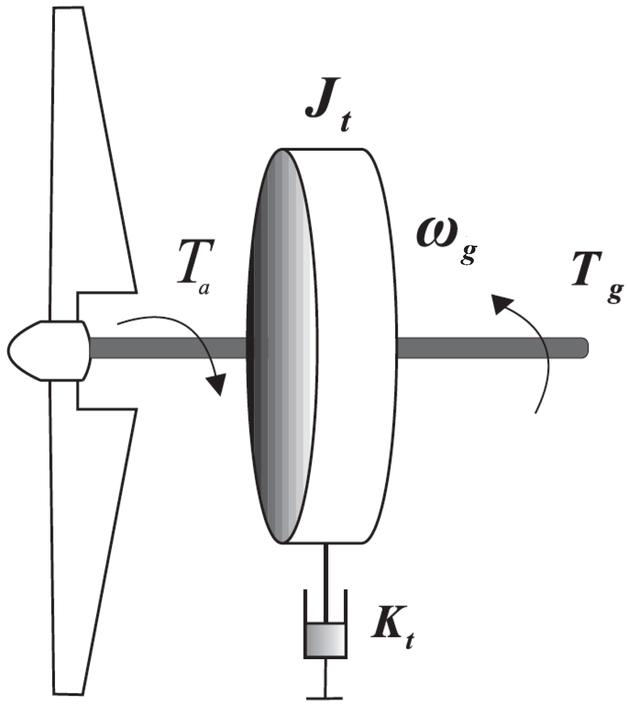
2. System Modeling

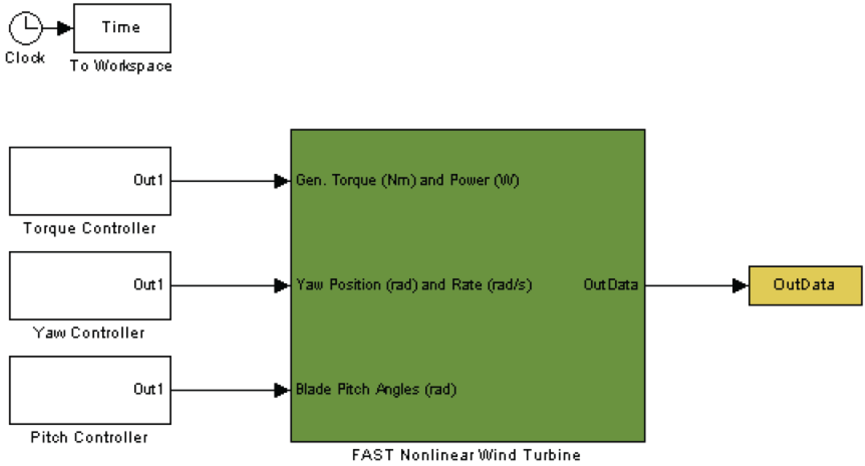
3. Brief Simulator Description (FAST)
4. Control Strategy

4.1. Torque Controller
4.2. Pitch Controller
5. Simulation Results

| Number of blades | 3 |
| Height of tower | 82.39 m |
| Rotor diameter | 70 m |
| Rated power | 1.5 MW |
| Gearbox ratio | 87.965 |
| Nominal rotor speed (ωn) | 20 rpm |
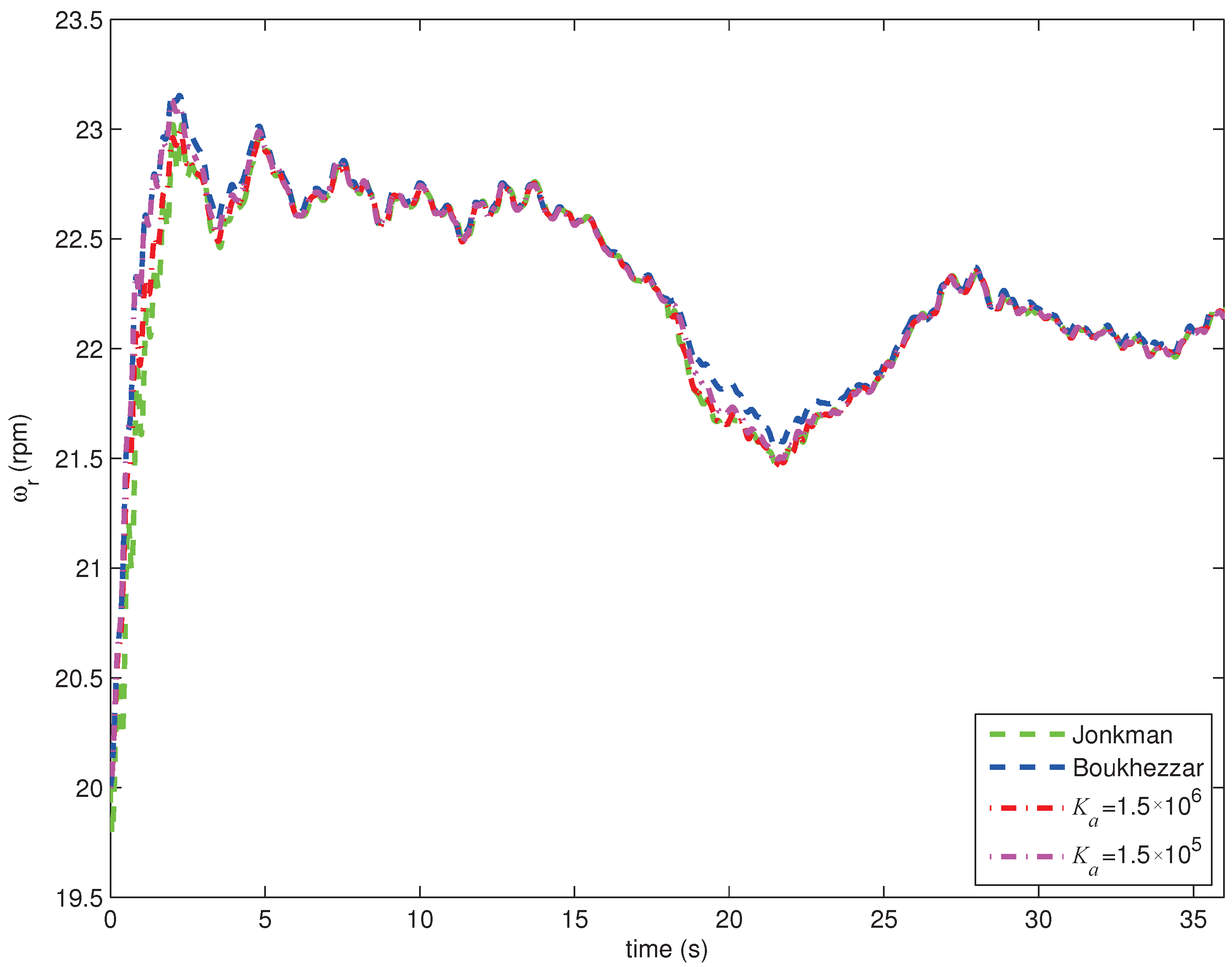
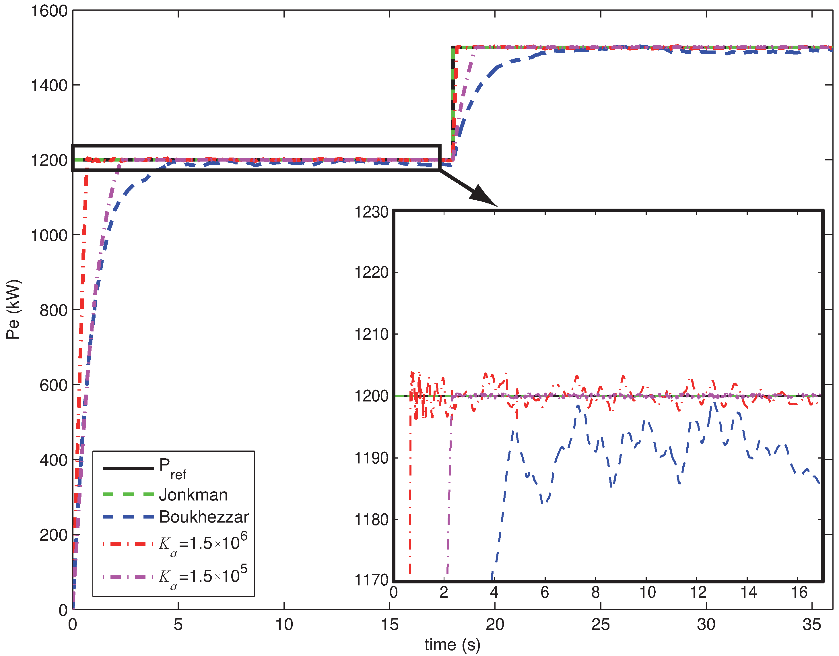
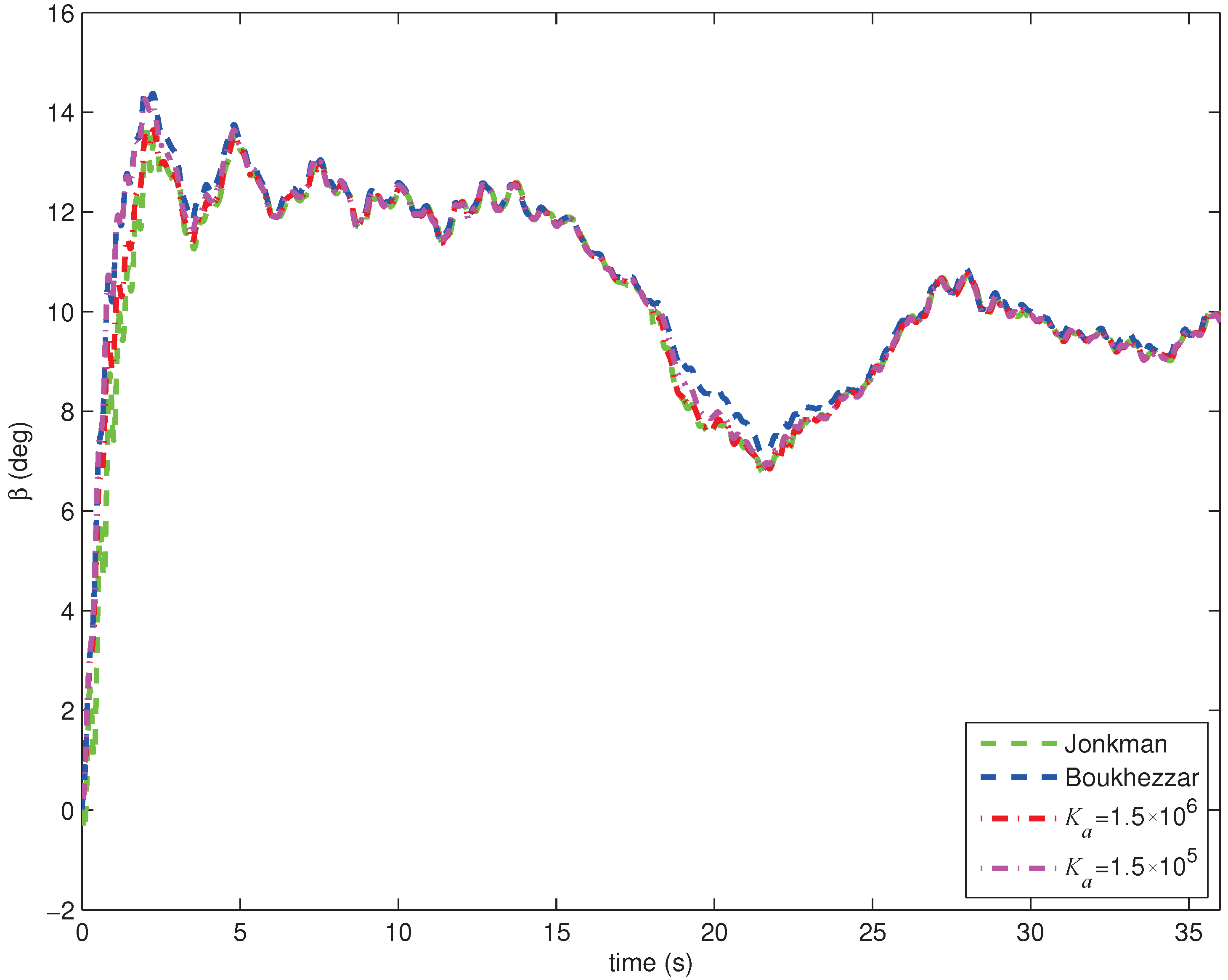
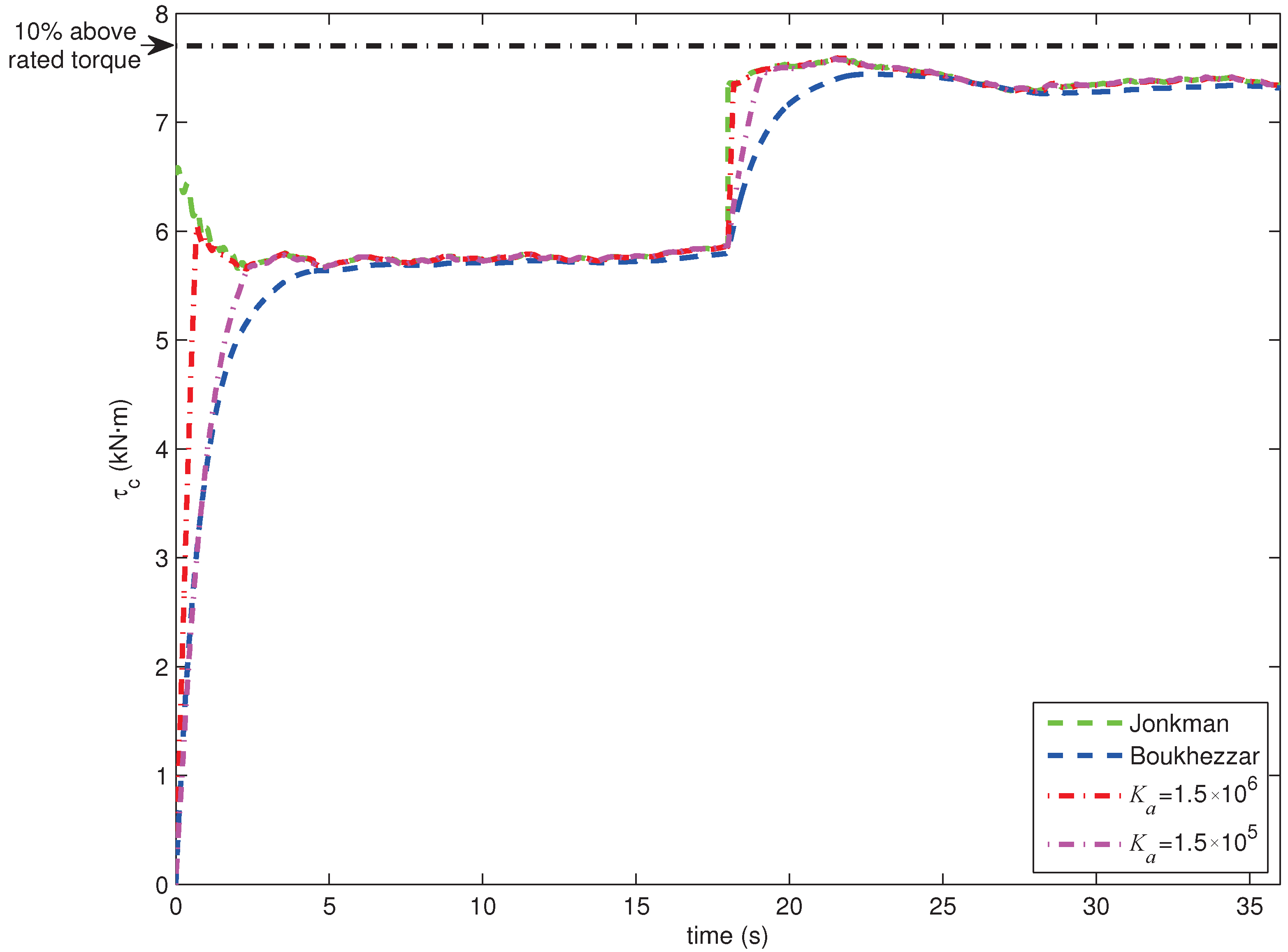
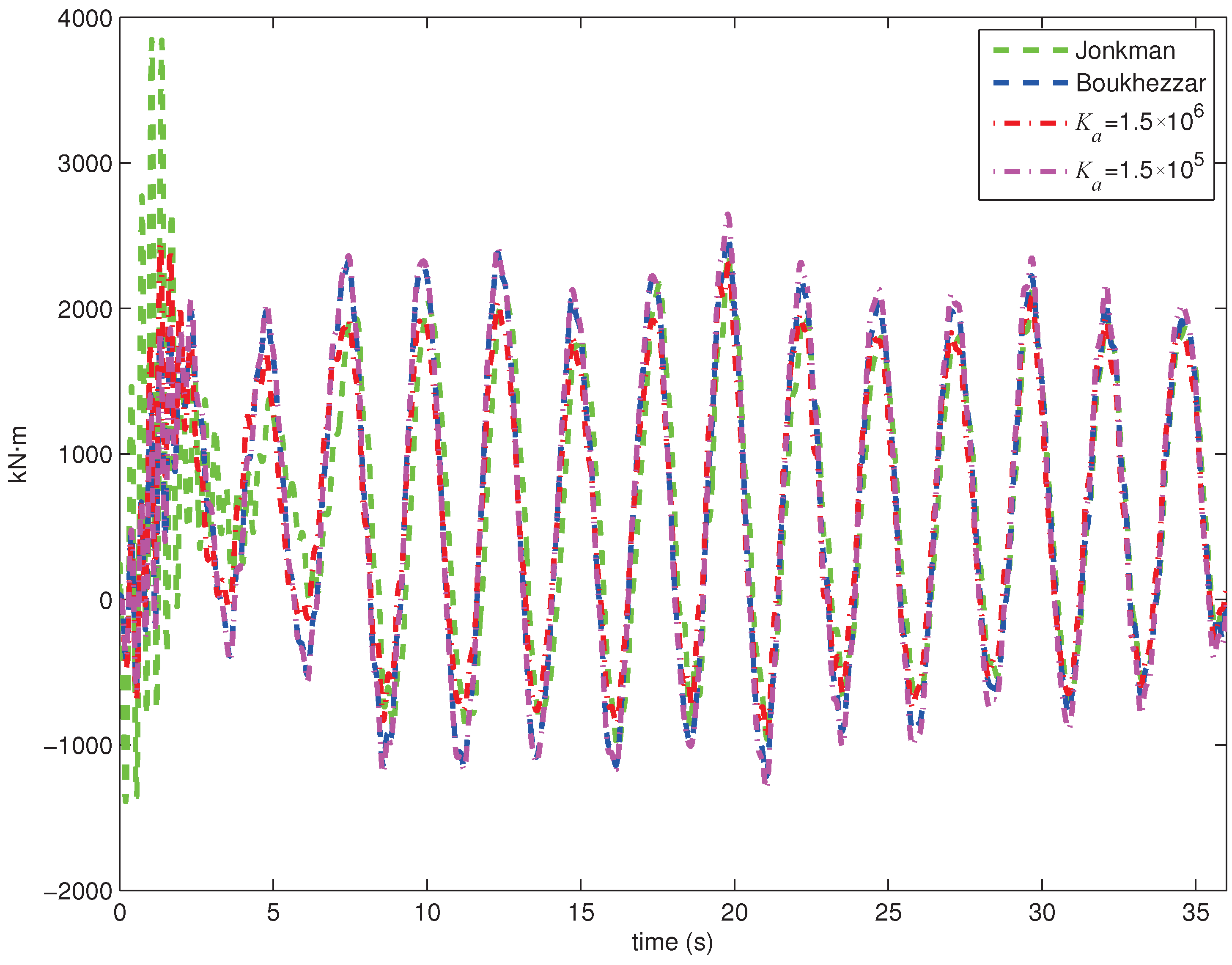
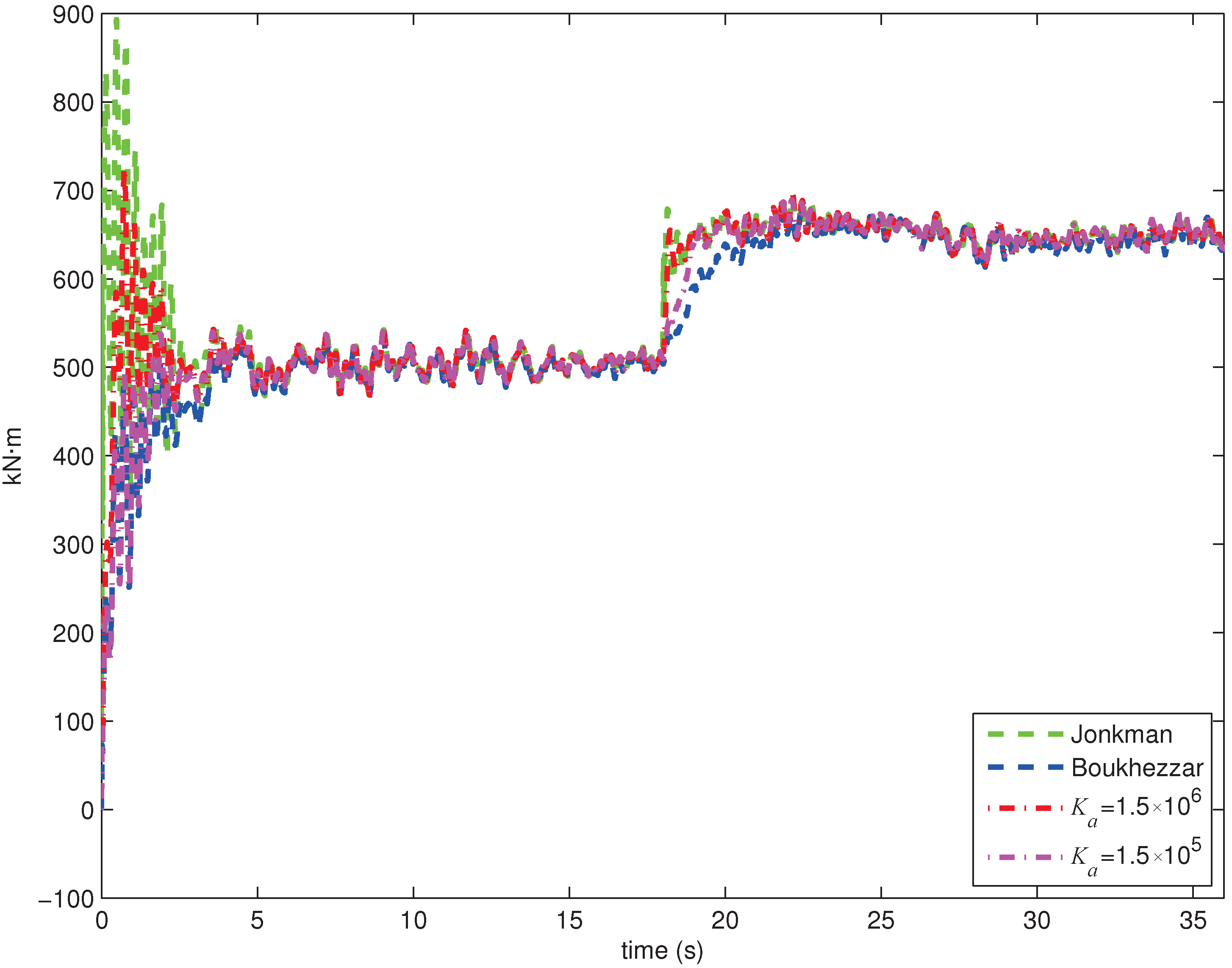
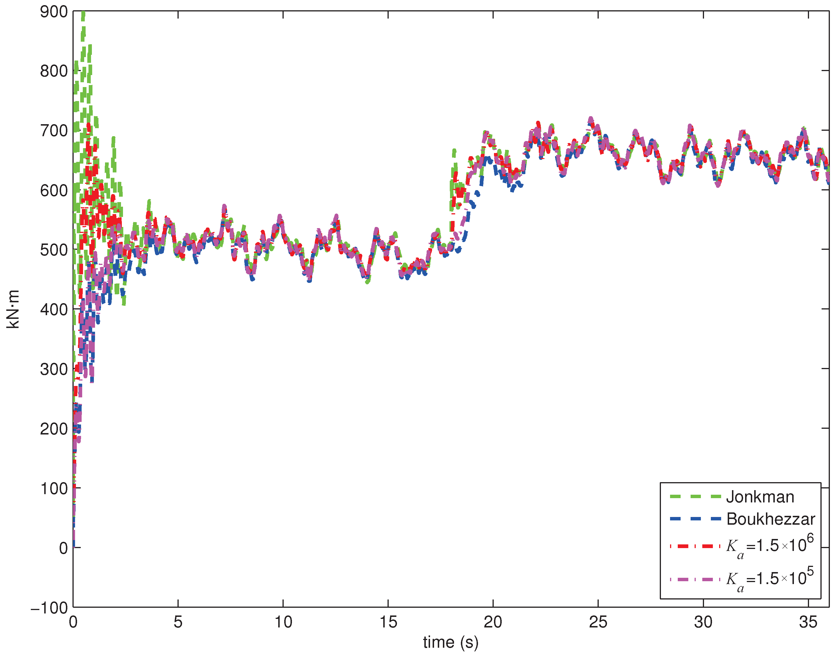
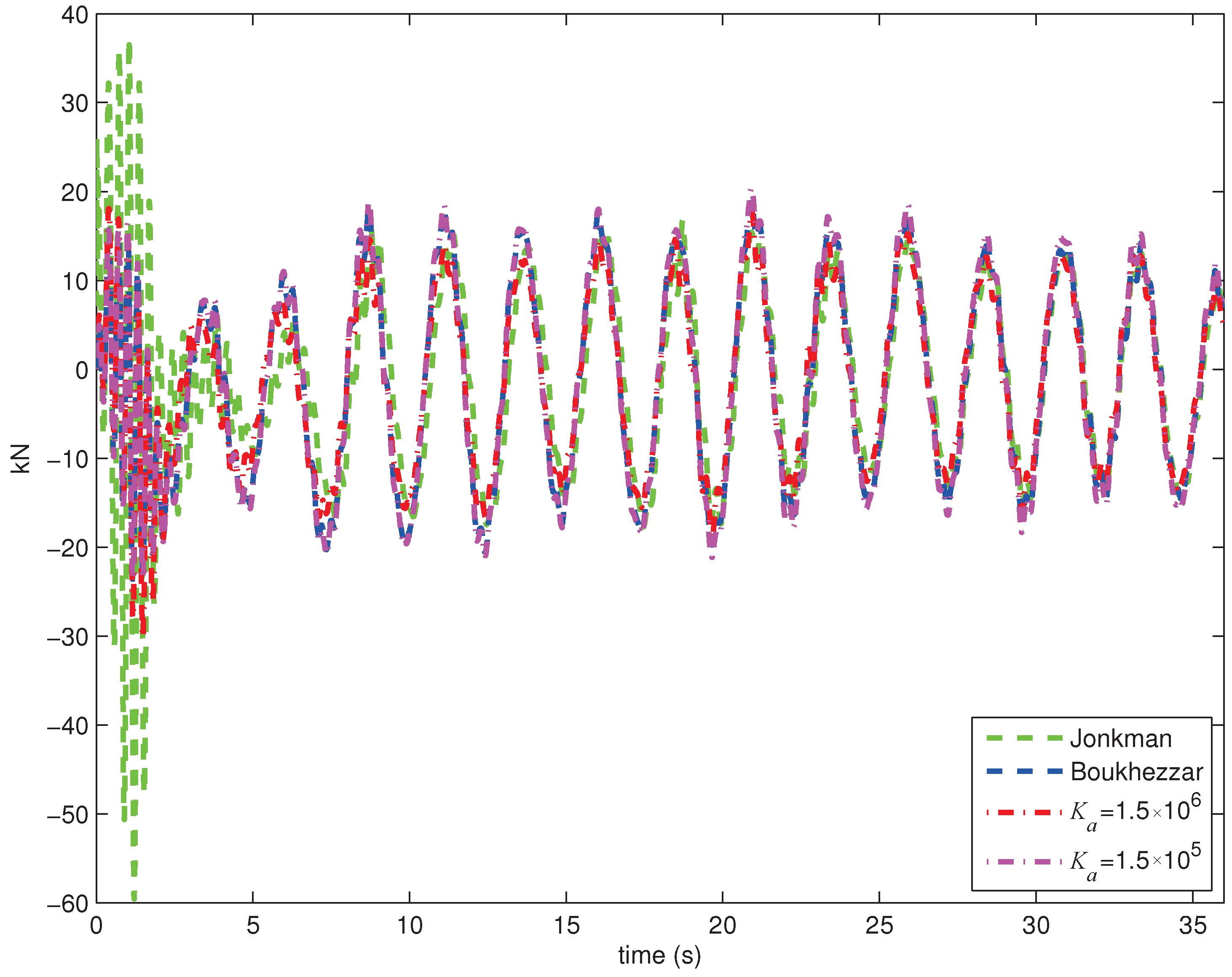
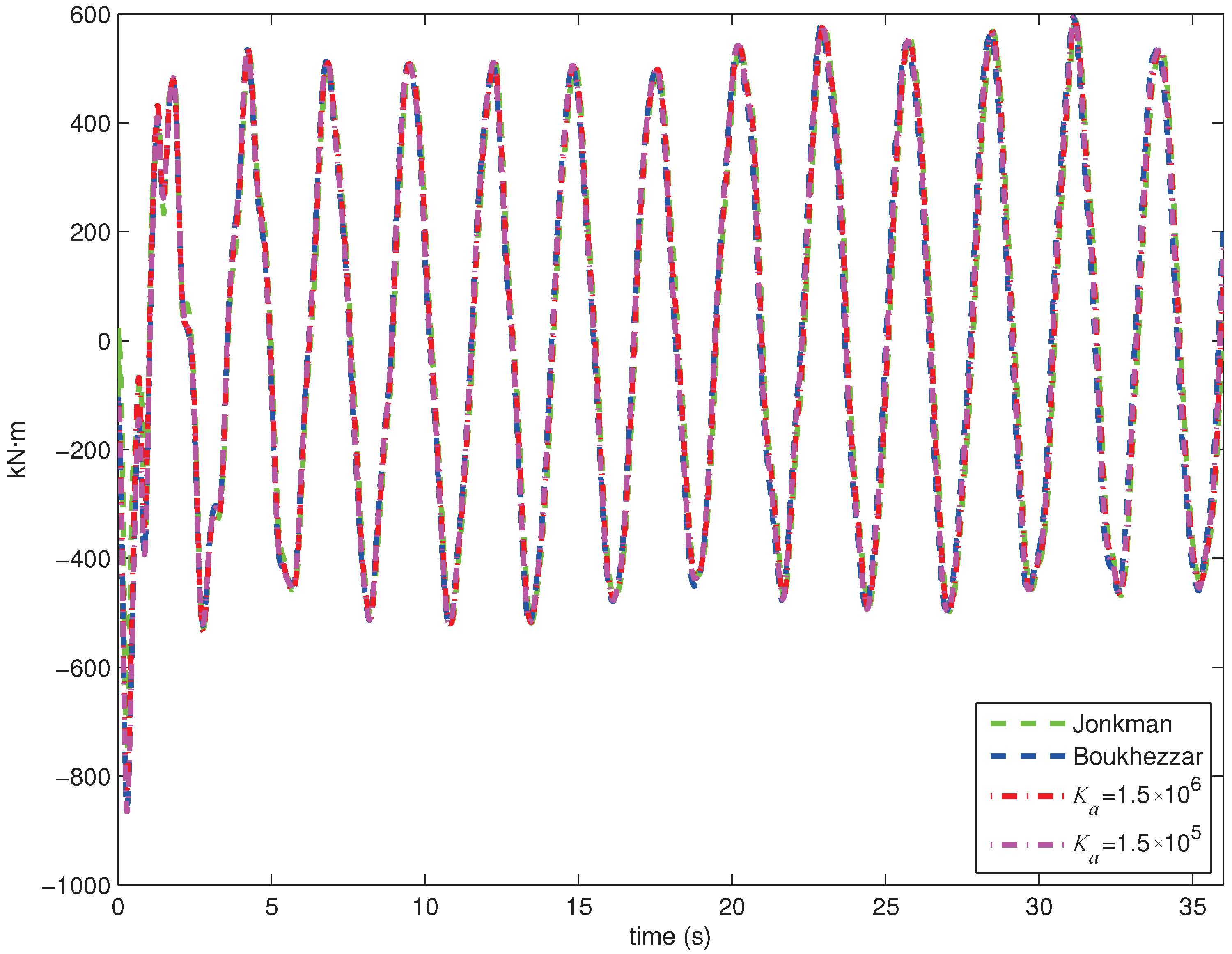
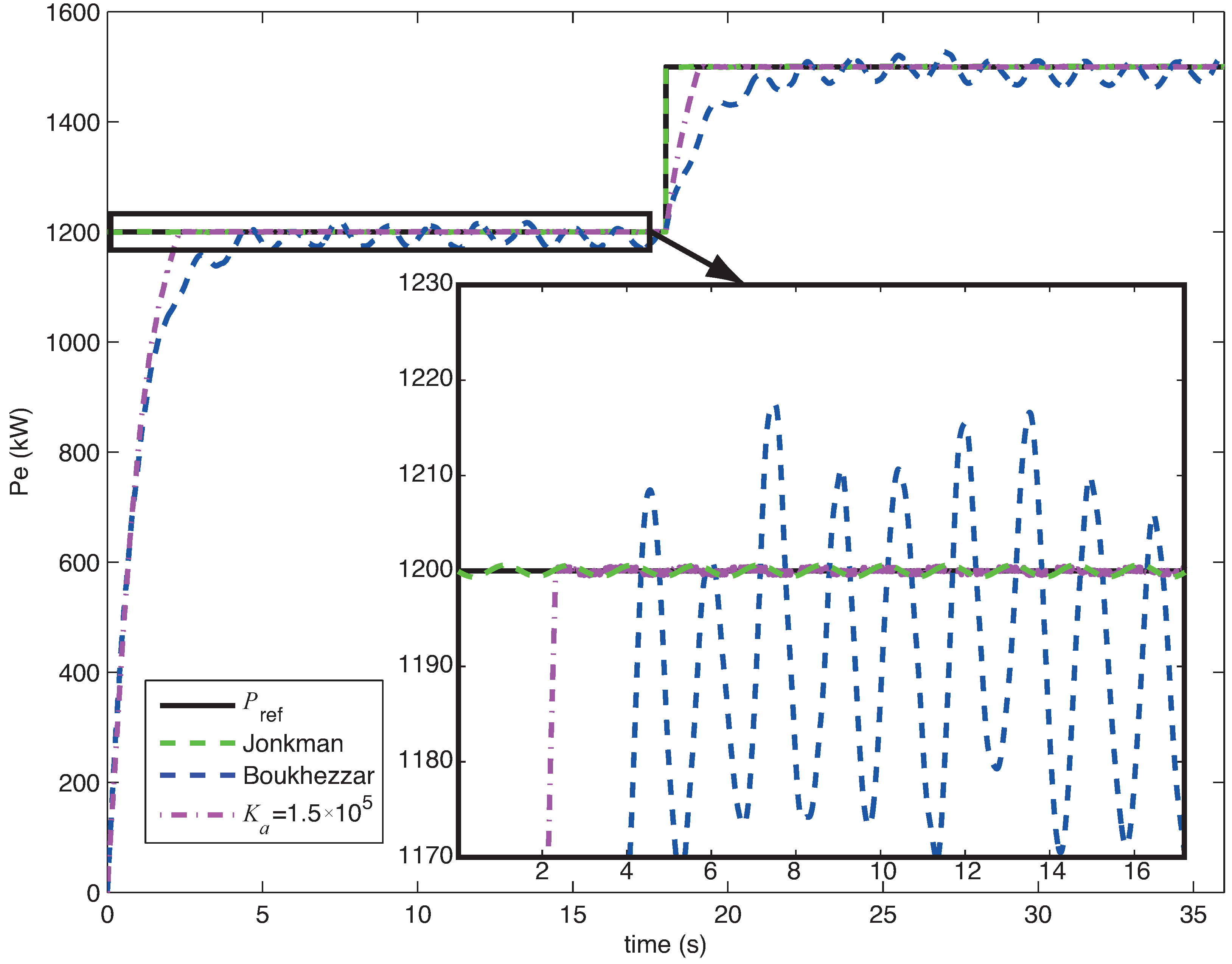
5.1. Torque and Pitch Control


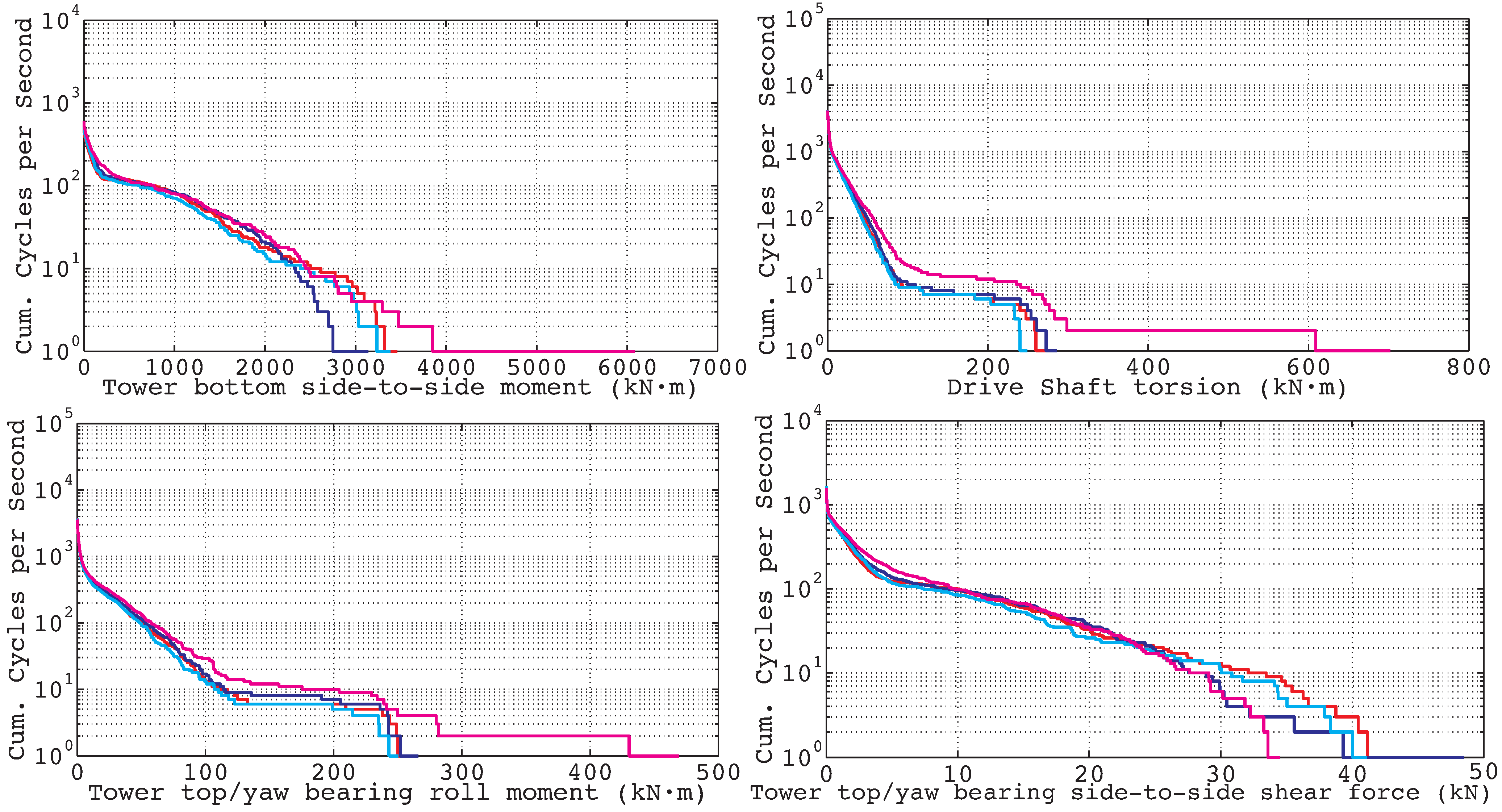
| Units | SN Slope | Kα = 1.5 × 10⁵ | Kα = 1.5 × 10⁶ | Boukhezzar | Jonkman | |
|---|---|---|---|---|---|---|
| Tower bottom side-to-side | (kN·m) | 3 | 1.255 × 10³ | 1.195 × 10³ | 1.174 × 10³ | 1.418 × 10³ |
| Drive shaft | (kN·m) | 6.5 | 1.386 × 10² | 1.450 × 10² | 1.295 × 10² | 3.080 × 10² |
| Tower top/yaw bearing roll | (kN·m) | 3 | 7.699 × 101 | 8.144 × 101 | 7.338 × 101 | 1.083 × 10² |
| Tower top/yaw side-to-side | kN | 3 | 1.555 × 101 | 1.501 × 101 | 1.473 × 101 | 1.443 × 101 |
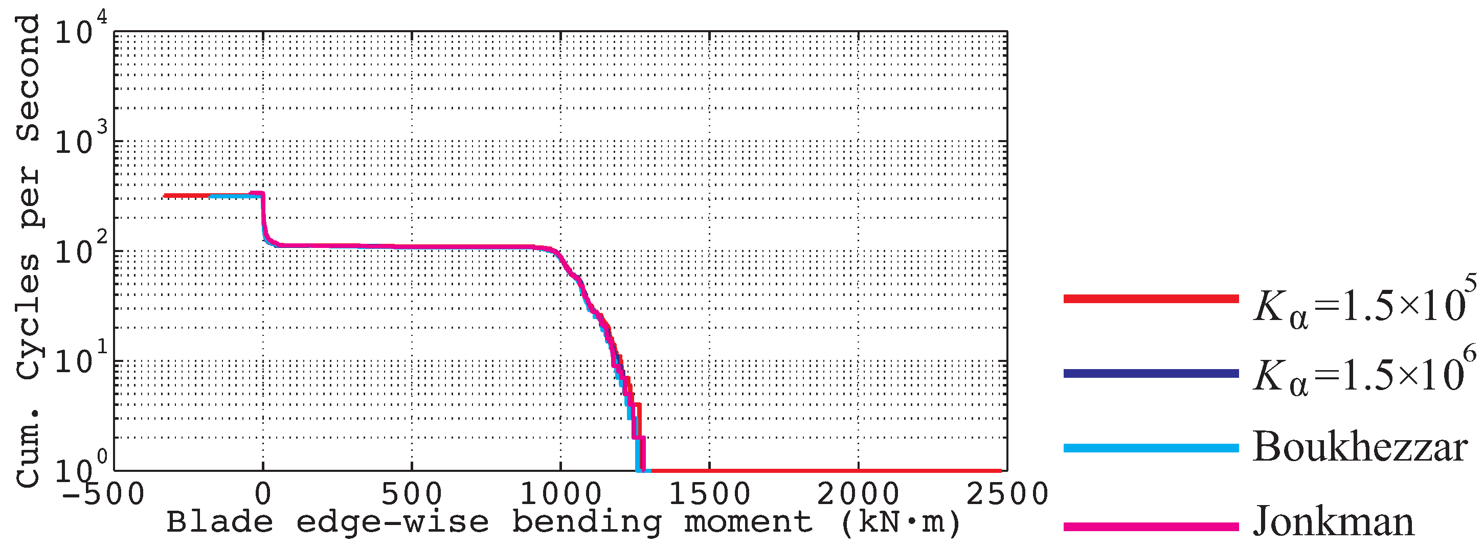
| Blade edge-wise bending | (kN·m) | 8 | 1.237 × 10³ | 9.599 × 10² | 9.562 × 10² | 9.595 × 10² |

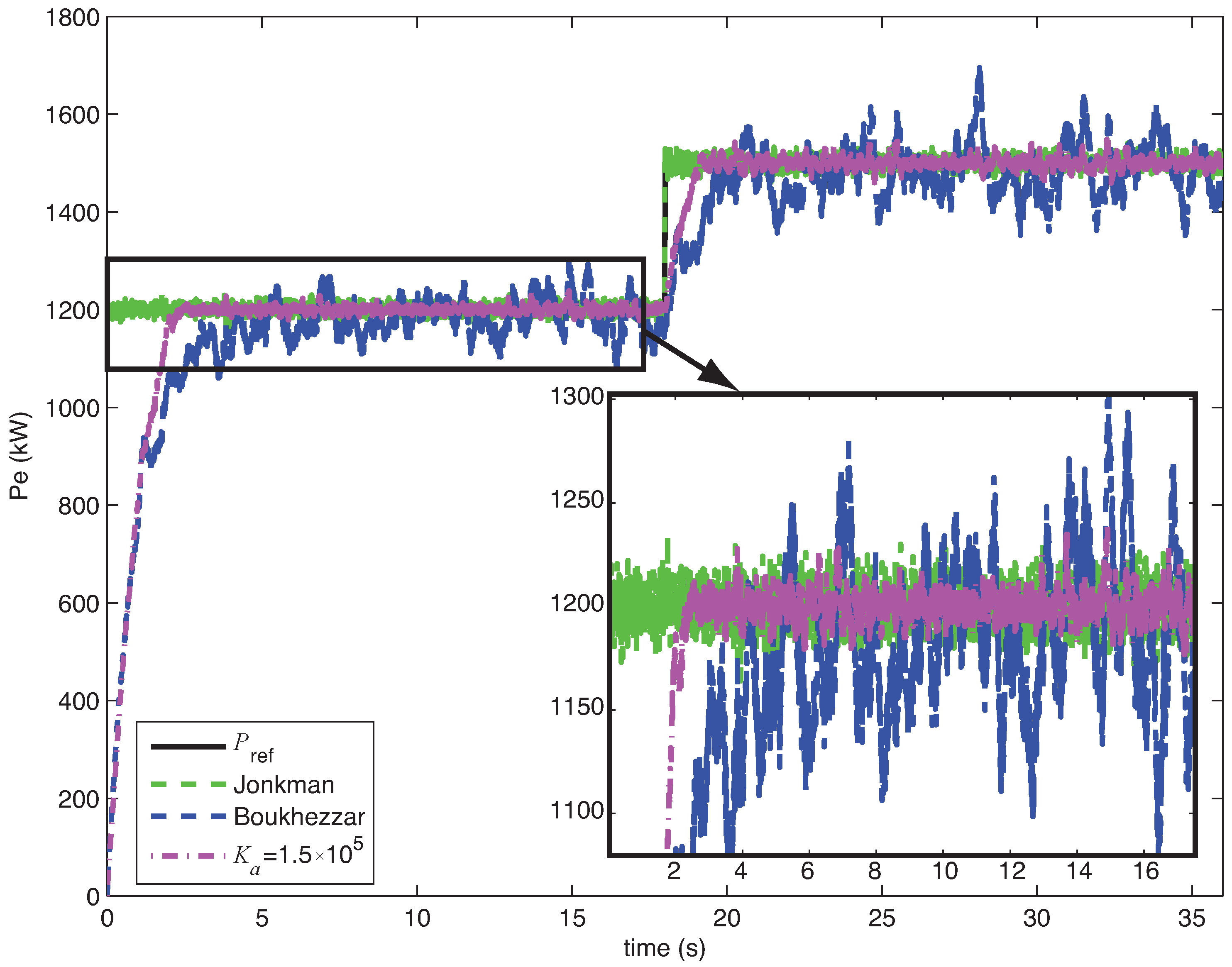
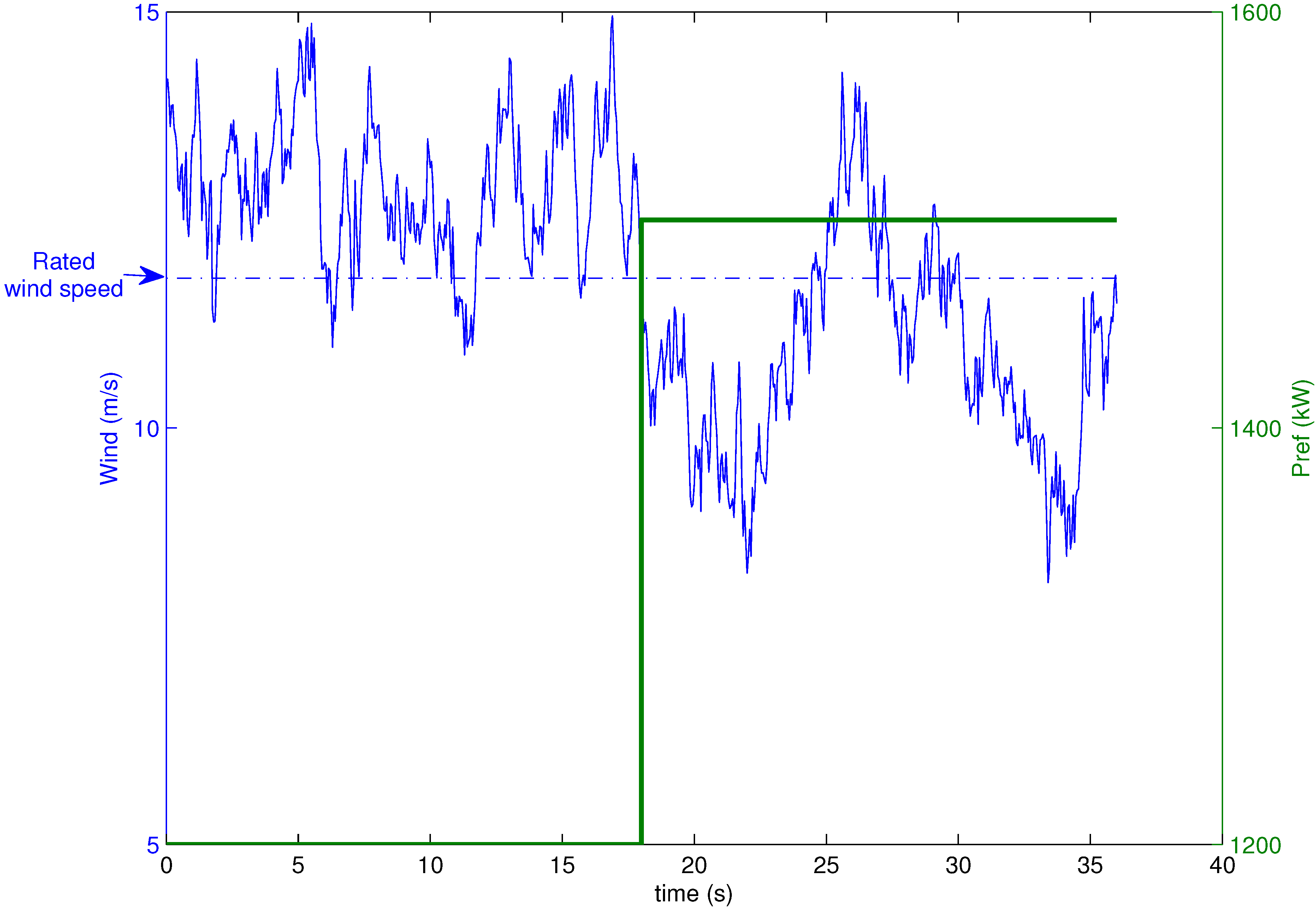
5.2. Torque and Pitch Control with Noisy Signals

6. Conclusions
- The proposed controller ensures finite time stability. Thus, the proposed controller more precisely reaches the desired power reference than exponentially stable controllers, such as [10].
- The proposed controller allows for selection of the settling time by properly defining the values of the parameters a and in Equation (4). Thus, our controller can be adjusted to obtain intermediate controllers with settling times that are closer to the Jonkman or Boukhezzar controller.
- The proposed simple nonlinear torque controller does not require information regarding the turbine total external damping or the turbine total inertia; it only requires the generator speed and electrical power of the WT. Thus, the proposed controller is easily applicable to other WTs. Using a simpler model than in [10], better results can be obtained.
- The proposed controller achieves the desired compromise between loads and the ability to track changes in the desired power.
- The proposed controller is more robust to periodic noise signals and does not require filters in this case.
Acknowledgments
References
- Burton, T.; Sharpe, D.; Jenkins, N.; Bossanyi, E. Wind Energy Handbook; Wiley: Chichester, UK, 2001. [Google Scholar]
- Zinger, D.; Muljadi, E. Annualized wind energy improvement using variable speeds. IEEE Trans. Ind. Appl. 1997, 33, 1444–1447. [Google Scholar] [CrossRef]
- Kusiak, A.; Zhang, Z. Control of wind turbine power and vibration with a data-driven approach. Renew. Energy 2012, 43, 73–82. [Google Scholar] [CrossRef]
- Hassan, H.M.; Eishafei, A.L.; Farag, W.A.; Saad, M.S. A robust LMI-based pitch controller for large wind turbines. Renew. Energy 2012, 44, 63–71. [Google Scholar] [CrossRef]
- Sandquist, F.; Moe, G.; Anaya-Lara, O. Individual pitch control of horizontal axis wind turbines. J. Offshore Mech. Arctic Eng.-Trans. ASME 2012, 134. [Google Scholar] [CrossRef]
- Joo, Y.; Back, J. Power regulation of variable speed wind turbines using pitch control based on disturbance observer. J. Electr. Eng. Technol. 2012, 7, 273–280. [Google Scholar] [CrossRef]
- Diaz de Corcuera, A.; Pujana-Arrese, A.; Ezquerra, J.M.; Segurola, E.; Landaluze, J. H-infinity based control for load mitigation in wind turbines. Energies 2012, 5, 938–967. [Google Scholar] [CrossRef]
- Soliman, M.; Malik, O.P.; Westwick, D.T. Multiple Model MIMO Predictive Control for Variable Speed Variable Pitch Wind Turbines. In Proceedings of the American Control Conference, Baltimore, MD, USA, 30 June–2 July 2010.
- Jonkman, J. NWTC Design Codes (FAST). Available online: http://wind.nrel.gov/designcodes/simulators/fast/ (accessed on 8 March 2012).
- Boukhezzar, B.; Lupu, L.; Siguerdidjane, H.; Hand, M. Multivariable control strategy for variable speed, variable pitch wind turbines. Renew. Energy 2007, 32, 1273–1287. [Google Scholar] [CrossRef]
- Jonkman, J.M.; Butterfield, S.; Musial, W.; Scott, G. Definition of a 5-MW Reference Wind Turbine for Offshore System Development; Technical Report NREL/TP-500-38060; National Renewable Energy Laboratory: Golden, CO, USA, 2009.
- Slootweg, J.; Polinder, H.; Kling, W. Dynamic Modelling of a Wind Turbine with Doubly Fed Induction Generator. In Proceedings of the Power Engineering Society Summer Meeting, 15–19 July 2001; Volume 1, pp. 644–649.
- Song, Y.; Dhinakaran, B.; Bao, X. Variable speed control of wind turbines using nonlinear and adaptive algorithms. J. Wind Eng. Ind. Aerodyn. 2000, 85, 293–308. [Google Scholar] [CrossRef]
- De Battista, H.; Puleston, P.; Mantz, R.; Christiansen, C. Sliding mode control of wind energy systems with DOIG-power efficiency and torsional dynamics optimization. IEEE Trans. Power Syst. 2000, 15, 728–734. [Google Scholar] [CrossRef]
- Khezami, N.; Braiek, N.B.; Guillaud, X. Wind turbine power tracking using an improved multimodel quadratic approach. Int. Soc. Autom. Trans. 2010, 49, 326–334. [Google Scholar] [CrossRef] [PubMed]
- Acho, L.; Vidal, Y.; Pozo, F. Robust variable speed control of a wind turbine. Int. J. Innov. Comput. Inf. Control 2010, 6, 1925–1933. [Google Scholar]
- Beltran, B.; Ahmed-Ali, T.; Benbouzid, M. High-order sliding-mode control of variable-speed wind turbines. IEEE Trans. Ind. Electr. 2009, 56, 3314–3321. [Google Scholar] [CrossRef]
- Manjock, A. Design Codes FAST and ADAMS for Load Calculations of Onshore Wind Turbines, 2005; National Renewable Energy Laboratory (NREL): Golden, CO, USA, 2005.
- Beltran, B.; Ahmed-Ali, T.; El Hachemi Benbouzid, M. Sliding mode power control of variable-speed wind energy conversion systems. IEEE Trans. Energy Convers. 2008, 23, 551–558. [Google Scholar] [CrossRef]
- Bhat, S.; Bernstein, D. Finite-Time Stability of Homogeneous Systems. In Proceedings of the American Control Conference, Albuquerque, NM, USA, 4–6 June 1997; Volume 4, pp. 2513–2514.
- Beaty, H.W. Handbook of Electric Power Calculations, 3rd ed.; McGraw-Hill: New York, NY, USA, 2001; Volume 1. [Google Scholar]
- Spong, M.W.; Vidyasagar, M. Robot Dynamics and Control; John Wiley and Sons: Hoboken, NJ, USA, 1989. [Google Scholar]
- Pao, L.; Johnson, K. A Tutorial on the Dynamics and Control of Wind Turbines and Wind Farms. In Proceedings of the American Control Conference, Boulder, CO, USA, 10–12 June 2009; pp. 2076–2089.
- Hayman, G. NWTC Design Codes (MCrunch). Available online: http://wind.nrel.gov/designcodes/postprocessors/mcrunch/ (accessed on 6 June 2012).
- Malcolm, D.J.; Hansen, A.C. WindPACT Turbine Rotor Design Study; Technical Report NREL/SR 500-32495; National Renewable Energy Laboratory: Golden, CO, USA, 2002.
- Brown, L.J.; Zhang, Q. Periodic disturbance cancellation with uncertain frequency. Automatica 2004, 40, 631–637. [Google Scholar] [CrossRef]
- Wu, B.; Bodson, M. Direct adaptive cancellation of periodic disturbances for multivariable plants. IEEE Trans. Speech Audio Process. 2003, 11, 538–548. [Google Scholar]
© 2012 by the authors; licensee MDPI, Basel, Switzerland. This article is an open access article distributed under the terms and conditions of the Creative Commons Attribution license (http://creativecommons.org/licenses/by/3.0/).
Share and Cite
Vidal, Y.; Acho, L.; Luo, N.; Zapateiro, M.; Pozo, F. Power Control Design for Variable-Speed Wind Turbines. Energies 2012, 5, 3033-3050. https://doi.org/10.3390/en5083033
Vidal Y, Acho L, Luo N, Zapateiro M, Pozo F. Power Control Design for Variable-Speed Wind Turbines. Energies. 2012; 5(8):3033-3050. https://doi.org/10.3390/en5083033
Chicago/Turabian StyleVidal, Yolanda, Leonardo Acho, Ningsu Luo, Mauricio Zapateiro, and Francesc Pozo. 2012. "Power Control Design for Variable-Speed Wind Turbines" Energies 5, no. 8: 3033-3050. https://doi.org/10.3390/en5083033
APA StyleVidal, Y., Acho, L., Luo, N., Zapateiro, M., & Pozo, F. (2012). Power Control Design for Variable-Speed Wind Turbines. Energies, 5(8), 3033-3050. https://doi.org/10.3390/en5083033