1. Introduction
Increasing concern about environmental problems and the shortage and rising costs of fossil fuels have promoted a growing interest in massive integration of renewable energy sources in power systems. Electrical grids on islands are very appropriate for the large scale installation of renewable sources for several reasons. Costs derived from shipping fossil fuels to islands are very high and transport can cause environmental problems such as greenhouse gas emissions and fortuitous fuel spills. In addition, on many islands, there are numerous renewable energy sources which can be exploited.
However, some important technical drawbacks can also arise. Power supplied by renewable sources, such as the wind, is intermittent and not easily predictable. These oscillations in the primary power supply can produce instantaneous differences in the necessary balance between generation and demand. As a consequence, important variations in frequency and voltage levels, which can affect the electric power system stability, can appear. These problems are serious in small size isolated grids, and therefore a continuous control on the instantaneous power supplied by the renewable energy sources is required [
1].
This is the case of the new electrical generation system structure that will be installed on El Hierro, in the Canary Islands, Spain. The short-term goal is that this weak grid will be completely supplied by renewable energy, where a wind farm will act as the main electrical power source. This wind power plant will be complemented with a pumped storage hydropower plant, which is intended to offset wind randomness. The system will also conserve the diesel-engine driven generators, presently installed on the island as the main energy supply, to act in case of emergency. They will be used only in situations when neither wind resource nor hydraulic energy is available. The aim is to establish how many conventional groups are necessary to remain connected to the grid to be able to maintain stability, during a major grid disturbance, in a worst case operation scenario. This minimum number will be determined based on the inertial rotating mass energy and reactive current support needed.
A short-circuit fault in a grid can cause an instantaneous and sharp voltage decrease in all system nodes (voltage dip) [
2]. Relevant grid codes define the voltage conditions that must be withstood by wind generators in such cases, which are quite similar in different countries. Spanish code requirements in case of island grids, however, are among the most demanding international codes currently in force for wind power integration in electrical systems. This strict code has been precisely defined based on the special weaknesses of the Canary Islands’ electrical systems.
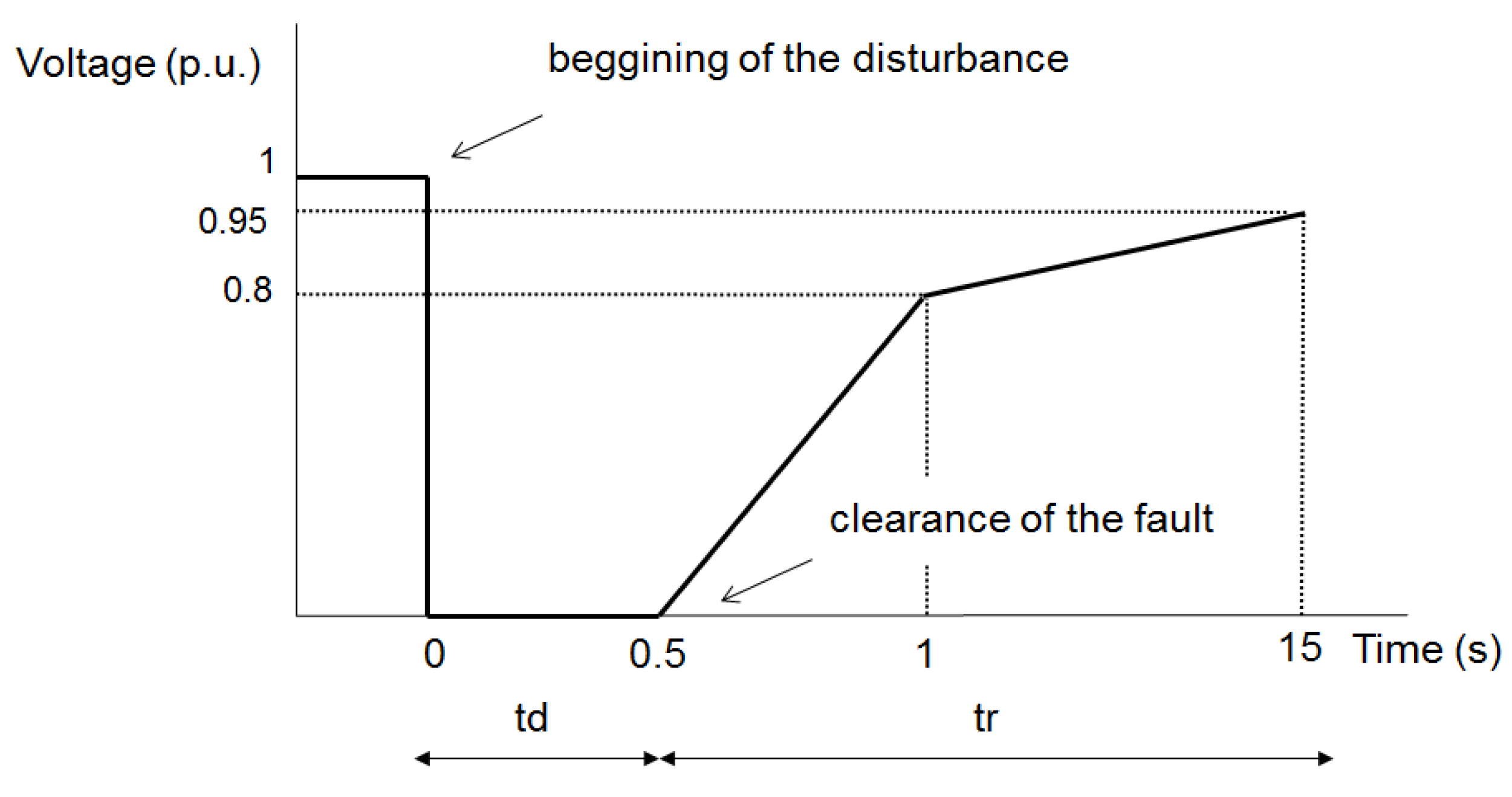
Figure 1 shows the voltage dip pattern in the code [
3].
Two areas can be distinguished in this figure: first, a deep period (td, in
Figure 1) from the fault occurrence to the instant the line protection trips; followed by a recovery period (tr, in
Figure1), once the fault has been cleared. During the first period, the connected generators must provide the maximum amount of reactive current, in order to contribute to the grid voltage restoration and to make it possible the fault detection by means of protection systems. Conventional generation units can supply up to five or six times their rated current in these circumstances. These units naturally contribute to recover the operating set point during the whole disturbance period by accommodating the power unbalance with the kinetic energy stored in their inertial rotating mass. On the other hand, variable-speed wind generators have limited capability to meet the voltage dip ride-through requirements, because of their electronic converters [
4].
Figure 1.
Voltage-time curve defining the limits of the voltage dip in the grid connection point that must be withstood by generators. Phase to ground voltage corresponds to faulted phases [
3].
Figure 1.
Voltage-time curve defining the limits of the voltage dip in the grid connection point that must be withstood by generators. Phase to ground voltage corresponds to faulted phases [
3].
In the technical literature, it is relatively common to find studies about managing power systems integrating a large percentage of renewable energy, particularly wind power. Information is much scarcer when referring to isolated grids.
Diesel units present a series of characteristics that make them the best choice in remote areas. They have a quick response to generation-load unbalance and are easy to control. These characteristics have promoted the integration of wind-diesel hybrid generation systems in power systems on islands. A wind-diesel model and its transient behavior are discussed in [
5]. In [
6], a strategy to control frequency variations in this kind of systems is proposed.
Furthermore, there are several papers that present the advantages of the combination of a pumped storage hydropower plant to stabilize the power supplied by a wind farm [
7]. This can be an acceptable solution for systems with wind power because it allows for regulating the system and the storage of large quantities of energy and, consequently, it reduces fuel dependence. The energy stored during windy periods can be later turned into electrical energy when the load exceeds the wind generation by means of a hydraulic turbine. This solution has increased the penetration index of wind power in isolated systems. Obviously, the main disadvantage of this solution is the high cost of these plants. Also, their environmental impact should be carefully analyzed and corrective measures to minimize these impacts are usually needed. Several examples of this topology are shown in [
8] for Canary Islands and for Crete [
9]. In the case of Greek Islands, these configurations have been extensively explored and the results reported in [
10,
11,
12].
This study completes the existing research results by presenting the stability studies in a new wind-pumped storage generation system that will be installed in the Canary Islands. It will be demonstrated the necessity to keep connected some conventional groups, supplying their kinetic energy, to face up to the worst possible disturbance. This kinetic energy will be quantified to establish a ratio between wind power installed and conventional units needed. The influence of the inertia over the recovery time will also be shown. These results can be applied to similar networks.
This work has been structured in the following parts:
Part 2 describes the planned El Hierro Island new electrical power system.
Part 3 shows the models employed in the transient stability modeling of the grid.
Part 4 analyzes the simulation results and defines the operation management strategy required to reach the goal proposed. Finally, conclusions are shown in
Part 5.
2. El Hierro Case Study
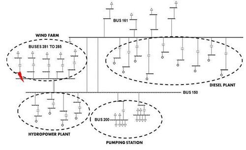
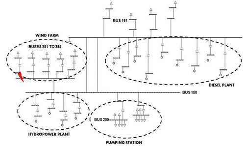
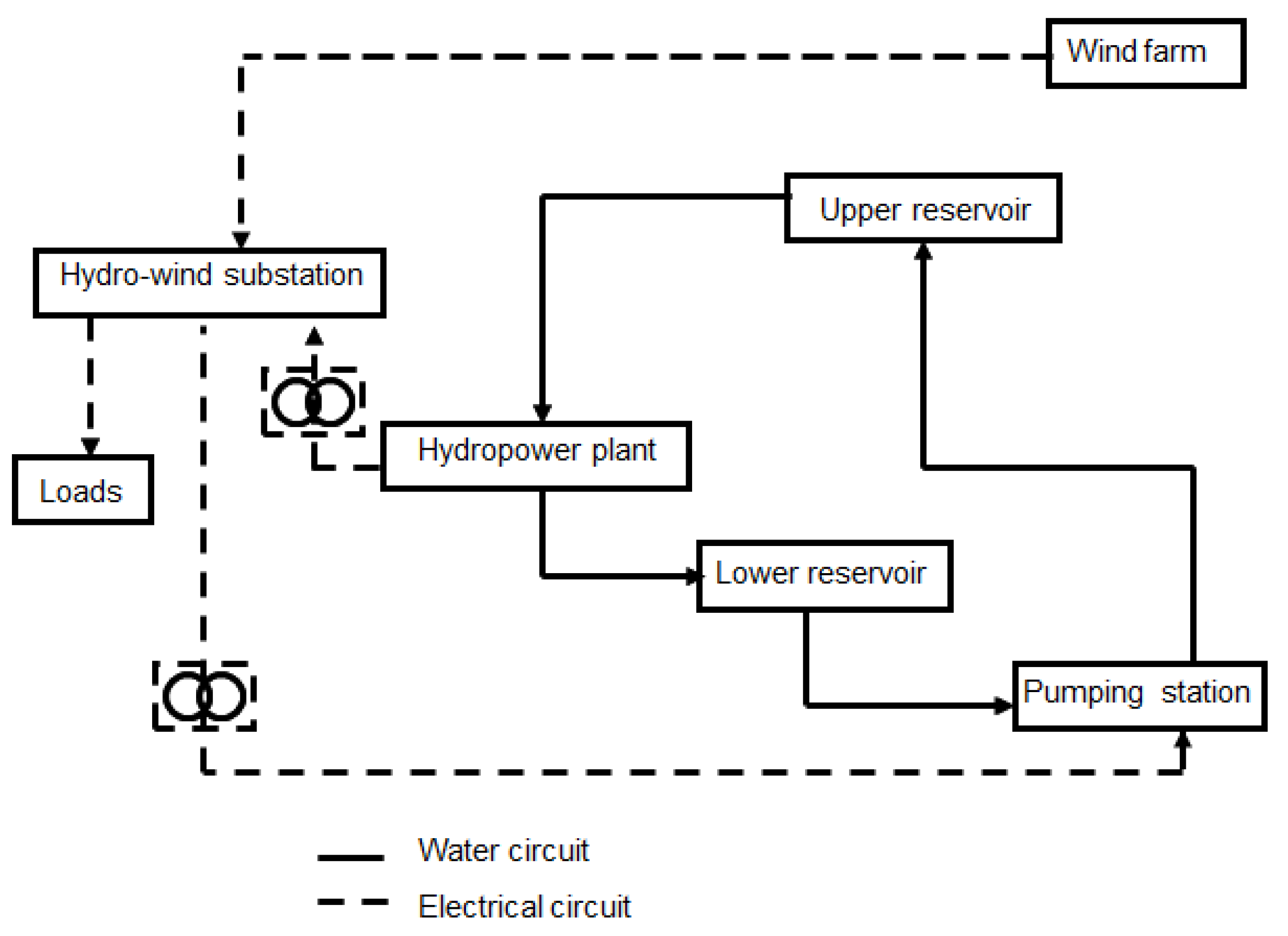
Figure 2 shows a schematicdiagram of the system whose management strategy is the objective of the present analysis.
Figure 2.
Wind-hydro system configuration.
Figure 2.
Wind-hydro system configuration.
This electrical power system has been dimensioned taking into account not only the actual demand in the island but also the expansion planned by the local government until 2015 [
13]. System data are shown in
Table 1.
Table 1.
System data.
| System Data | Value |
|---|
| Power installed (2011) | 13.9 MW |
| Power installed (2015) | 36.32 MW |
| Peak power demand (2011) | 8.15 MW |
| Peak foreseen power demand (2015) | 9.6 MW |
| Electric demand (2011) | 40 GWh |
The system, still under construction, will consist of an 11.5 MW wind farm with, a 6.8 MW pumping station, and an 11.3 MW hydropower plant. The existing Diesel power plant (13.9 MW), composed by nine units with rated power between 0.89 MW and 2.56 MW, will remain as a generation backup. The system is projected to be completely autonomous with renewable energy sources in normal operation scenarios and in emergency cases while water is available [
14]. In case there is not enough water in the reservoir it will be necessary to have the diesel units working at their technical minimum to reduce the time they need to operate at rated power. As it can be inferred from all these data, the system is clearly oversized to ensure that each generating technology, independently used, can completely cover the demand on the island.
The main power producer will be the wind farm, composed by five 2.3 MW wind turbines. Excess energy generated in low-demand periods will be used to pump water from a lower reservoir to an upper reservoir. The hydraulic circuit consists of two water reservoirs connected by two penstocks, the Pelton turbines and the pumping station. Because of the high net head (655 m), and in order to maximize the power-frequency control capability, the plant will be composed of four 2.83 MW Pelton turbines, with 2 m3/s maximum flow rate. The pumping station will be made up of a double busbar system, using one of the busbars for the starting with a speed controller. It will have six pumps, divided into two groups. Each group will consist of one 1600 kW variable-speed pump and three 600 kW fixed speed pumps. The pumping station has a double purpose: it has to store the surplus electric energy turning it into potential energy, but it also has to contribute to load-generation equilibrium and to reduce the imbalance when severe contingencies happen. Power absorbed by pumps will be variable depending on the system needs. The system will also have two electrical substations, one for the wind farm and the other one for the hydraulic power plant. Additionally the scheme will include a desalination plant.
3. Modeling
To represent the proposed system and to analyze its transient behavior facing to grid contingencies, a simulation model has been developed using the PSS/E
© software platform [
15]. Most of the conventional generator units and loads in the island power system have been represented using existing models in PSS/E libraries, but in order to model the dynamic operation of the wind farm it has been necessary to implement new specific models as “user-written models”. The main characteristics of the PSS/E existing models are shown in
Table 2.
The user-written model, which first version was developed by the authors in a previous work [
16], is able to represent the transient performance of any wind energy conversion system belonging to the Variable Speed Wind Turbine Synchronous Generator (VS-WTSG) technology.
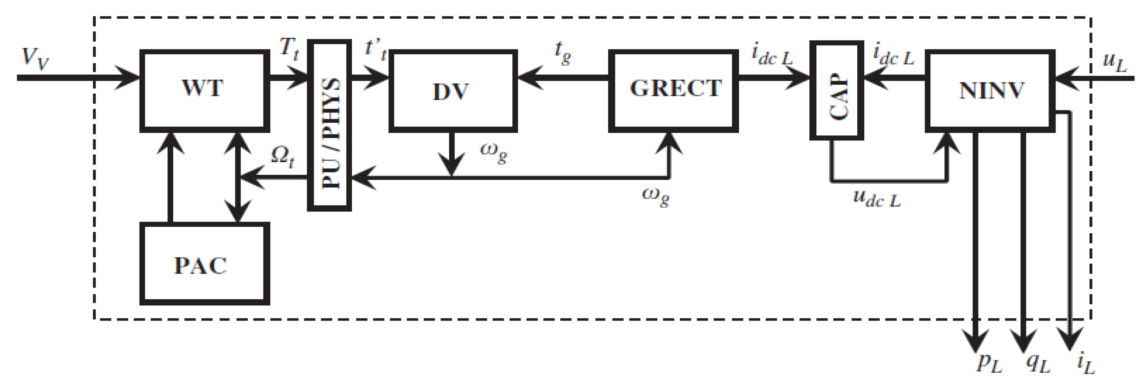
Figure 3 shows the general programming structure of the model, where the different simulation blocks are: the wind turbine aerodynamics (WT); the pitch angle controller (PAC); the mechanical drive system (DV); the group formed by generator, rectifier, and rectifier control (GRECT); the inverter and its control (NINV); the DC link (CAP); and a block to convert per unit quantities to physical ones (PU/PHYS).
The model described in [
16] has been improved to include some additional features of the new wind generators to be used in the system. Basically, these wind turbines incorporate controls to adapt their response, in terms of active and reactive power, to behave as much as possible as conventional synchronous machines. The function performed by each part of the model will be described below.
The wind turbine (WT) includes a dynamic model of a machine composed by a rotor with three blades and the pitch angle controller mechanism (PAC) to modify the blade pitch angle and, as a consequence, to limit the rotor speed and the generated power at any wind speed.
The mechanical drive system (DV) includes a dynamic model for the shaft coupling of the drive train. The electrical generation system (GRECT) includes a dynamic model of a salient pole synchronous generator, connected to a controlled rectifier that provides the torque control of the drive. That way, the wind turbine can follow the strategy of giving the maximum active power in each moment, or any other control on the generated active power.
Table 2.
PSS/E library models.
Table 2.
PSS/E library models.
| Component | Model name | Description |
|---|
| Conventional generator units |
|---|
| Generator | GENSAL | This model represents a salient-pole machine with quadratic saturation in d-axis, and its structure corresponds to the IEEE standard format type 2.1 and 2.2 for stability studies [17]. Parameters used for modeling the generator units are shown in Table A1 and Table A2. |
| Speed governor. Diesel | DEGOV1 | DEGOV1 is a model which presents two different ways for the droop control: by throttling the main valve or by feeding the electrical power. The second option has been selected for this application. |
| Speed governor. Hydraulic | HYGOV | HYGOV represents the unit composed by a hydraulic turbine, the penstock, and the speed governor for hydropower plants without limits in the upper or lower reservoir and without forebay. |
| Excitation system. Diesel | EXBAS | EXBAS model represent a standard AC type excitation system with rotating diodes consisting of a main source with non-controlled rectifiers and not affected by the external transients. |
| Excitation system. Hydraulic | IEEEX1 | IEEEX1 model uses a DC current generator with a switchboard as power source for the excitation and it corresponds to a DC1A IEEE standard model [18]. |
| Motor-pump units |
| Motor - pump | CIM6BL | These units consist of a pump coupled to a double-cage motor. The torque-speed curve of the pump has been adjusted by the following quadratic equation: In case of motor starting, T corresponds to the nominal torque value for the level of mechanical load connected to the system. Once the motor is running, T is determined in the power flow calculations and stored in an internal variable. |
Figure 3.
General block diagram of the wind generator model.
Figure 3.
General block diagram of the wind generator model.
The inverter module (NINV) includes the dynamic model of the control system on the active and reactive power transferred from the wind generator to the grid, through an inverter NINV connected back to back with the rectifier RECT. The dynamics of the active power transfer is defined by the voltage in the DC link capacitor (CAP).
The block called PU/PHYS converts the physical units in the aerodynamics part (WT + PAC) into per unit magnitudes in the part composed by the drive train (DV) and the electrical blocks (GRECT + CAP + NINV).
As shown in
Figure 3, the inputs to the model are the wind speed (
vV) and voltage (
uL), in module and phase, in the connection point. Wind speed enters to the model as an external function. The model outputs are the line current (
iL), and the active and reactive powers injected into the node (
pL and
qL).
The model reproduces the behavior of the wind conversion technology described previously. An internal block evaluates the turbine torque taking into account the input wind speed, blade geometry, and rotational speed conditions. The curve that relates the power coefficient (Cp) with the tip speed ratio (λ) is given by manufacturers depending on the blade pitch angle (β). In this case, this relationship has been obtained by using interpolation functions. The model is prepared to reproduce the actuation of the pitch angle controller which can change the angle β dynamically if wind turbine regulation is required, due to an excess of wind resource over the maximum or to a low demand situation.
The mechanical part has been modeled considering one lumped mass model including the blades, the hub, the rotor of the generator, the drive shafts (high and low speed), and the gearbox, if it exists.
As it is usual in models for stability studies, some simplifications have been considered: power electronic components are considered ideal, magnetic flux in the machine remains constant in the transient process, saturation effects are neglected as well as the dynamics of the excitation system, and damper windings effect and electromagnetic transients in the stator are also neglected.
When the generator supplies a determined quantity of energy and the inverter cannot inject it into the grid, for example in case of a voltage dip, it is also necessary to implement a strategy to protect the full converter DC link against an overvoltage, limiting the maximum capacitor voltage level.
Control of active power has the objective of avoiding load rejection actions as a primary frequency control. Active power control detects a change in the value of frequency, so it acts in the sense of recovering the rated value.
In the case of the reactive power, two controls have been defined. The first control establishes the injection/absorption of reactive power in normal operation conditions, with no disturbance in the network, and it has been implemented taking into account the working limits defined in the current regulations [
3]. The requirements are very similar to those imposed to conventional units. The second control, regulates the reactive power to be supplied in case of disturbance. The regulation system will try to maintain at any instant the reactive power level previous to the fault.
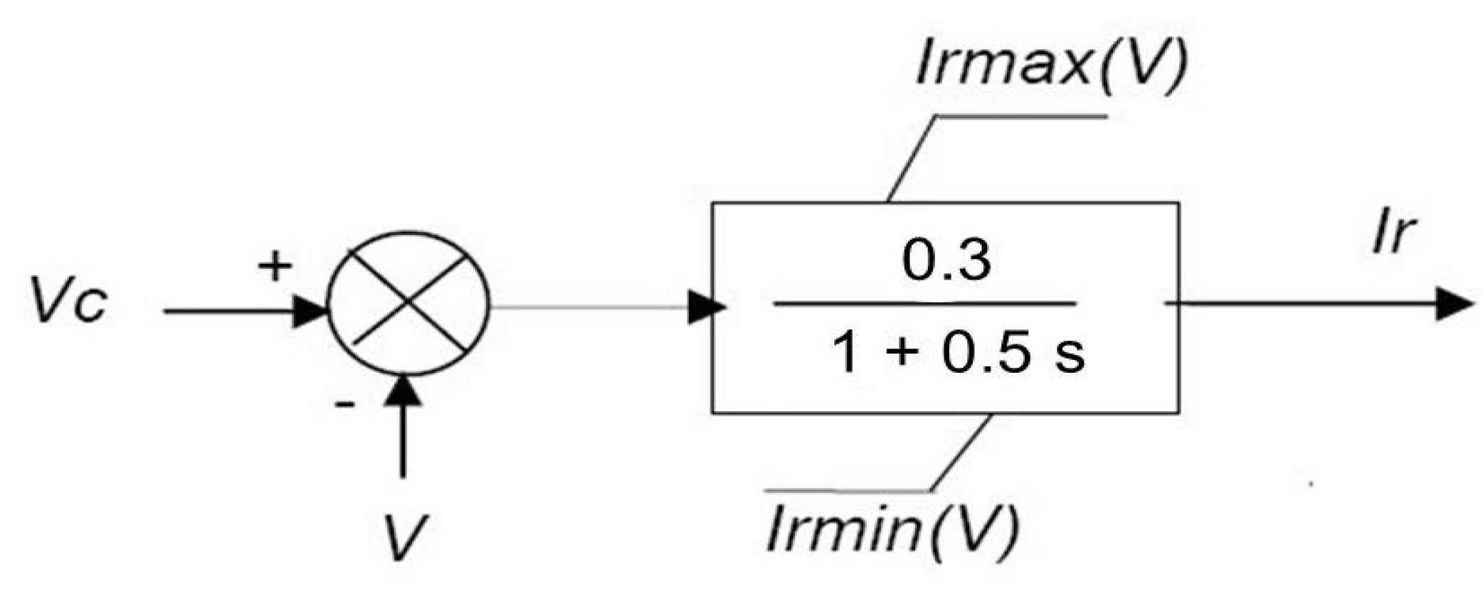
Figure 4 shows the block diagram for this control that has been added to the original model described in [
16].
Vc and
V represent the voltage setpoint and the measured value in the connection point. The reactive current to be supplied or absorbed is respectively limited by
Irmax and
Irmin.
Table A3 shows the values used in the simulation of the wind generators.
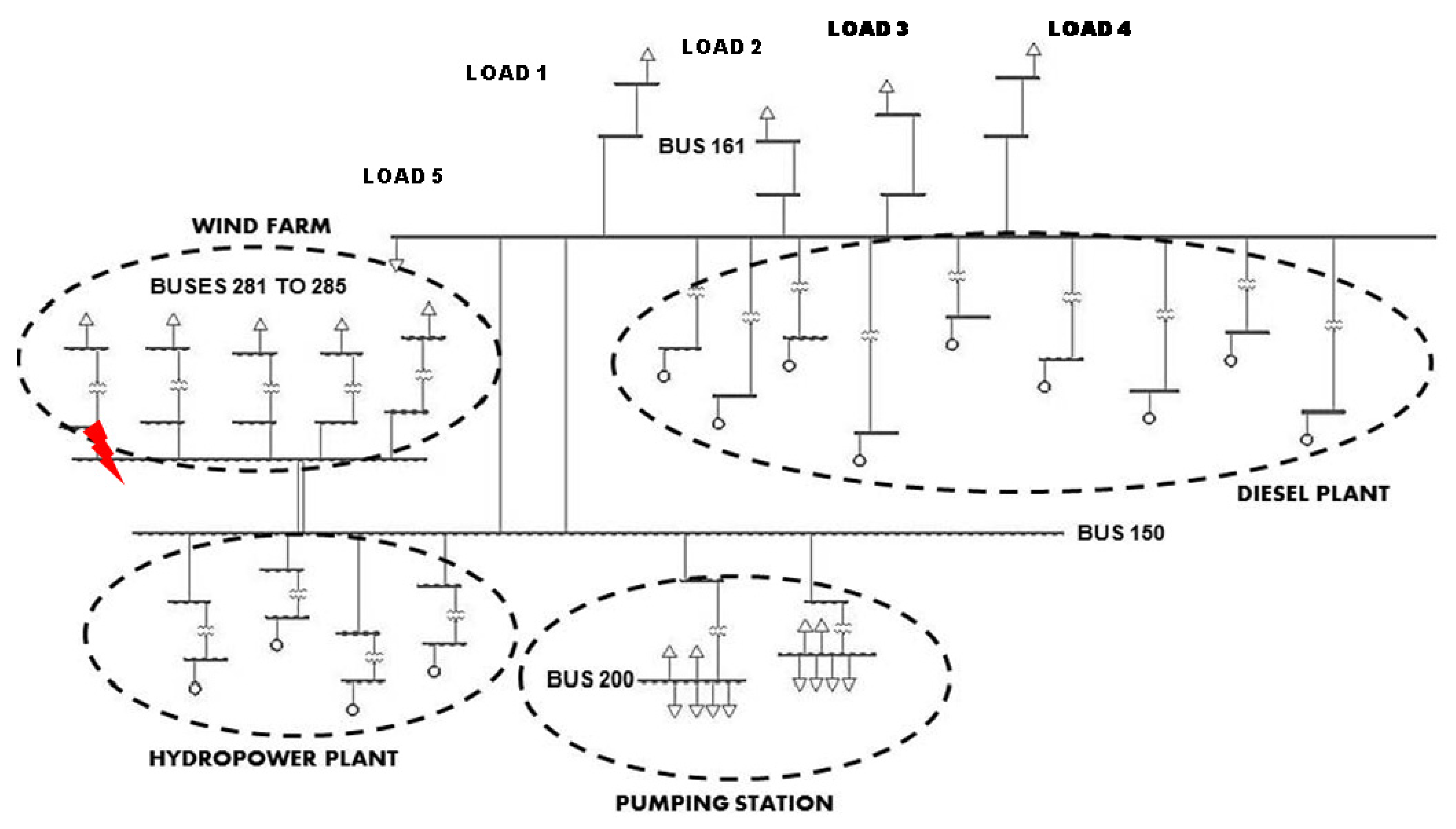
Figure 5 shows the PSS/E schematic view of the whole “El Hierro” generation system under analysis, which uses all the above described models. Together with the different generation power plants, the figure also shows the main distribution lines and loads. More details are given in
Table A4 and
Table A5. Loads from 1 to 4 represent the consumption at the end of the transmission lines while Load 5 stands for the desalination plant.
Figure 4.
Block diagram of the reactive power control in case of disturbance.
Figure 4.
Block diagram of the reactive power control in case of disturbance.
Figure 5.
PSS/E Schematic representation of “El Hierro” generation system.
Figure 5.
PSS/E Schematic representation of “El Hierro” generation system.
4. Stability Analysis in a Critical Operation Scenario
In the electric power system shown before, there are some operation conditions in which transient stability is severely at risk. This section presents the most relevant results of the worst case analysis, corresponding to the most critical disturbance while operating in the worst scenario. The aim is to define the best procedure strategy over the active elements in the system to guarantee that the operating conditions are always within adequate limits, both during the contingency and after clearing the fault. The scenarios analyzed here, with most of the energy coming from wind power, represent a challenge with unknown experience. The critical operating scenario takes place when the highest wind generation (11.5 MW) coincides with the lowest demand in the system (2.35 MW) because there are less conventional units connected. In this operating situation, the worst disturbance considered is a three-phase short circuit in the wind farm busbar. The most relevant point of this scene plot is that the system has to withstand the disturbance with no help from conventional synchronous units. On the other hand, and to make the best of the wind resource, the surplus energy coming from the wind turbines will be employed, conveniently, in pumping water from the lower to the upper reservoir. This combination of factors involves some problems:
- (1)
The contribution to the short-circuit current is noticeably reduced (from 6 or 7 p.u. to 1 p.u.) because of the electronic components of the wind electrical generator converter. This restriction implies not only a problem for the protection systems, which have to trip in case of a fault, but also delays the recovery period of the voltage levels in the network.
- (2)
Wind turbines are not able to return the whole inertial energy stored in their rotating masses, which adds difficulty to the frequency restoration in the grid after the fault clearance.
- (3)
In this operating scenario, most of the loads have an intense inductive character because they are induction motors connected to pumps in the pump station, which is working at its rated value (6.8 MW). These motors present a peak reactive current demand after the fault, so the time to recover after the voltage dip is very long. Some of the motors could trip during this recovery period due to the overcurrent associated with the low voltage level.
All these reasons show that it is necessary to maintain a minimum number of conventional units working as synchronous compensators to support the system with their inertia in case of a serious disturbance. In this grid, the availability of diesel and hydraulic units suggests that they can be used for this purpose. The developed tool has been used to explore this solution in the aspects related to the transient behavior of the system in this operating point. Next, we present the simulation results of the voltage time evolution in the most representative buses of the grid, and the shaft speed evolution in the wind machines, after a three-phase short circuit in the wind farm busbar (
Figure 5), in the critical operating scenario, defined before. The study was carried out for three cases, defined by the type and number of the technology used as a back-up generation source (Diesel or hydro):
- (1)
The best operating conditions, in which all the conventional units from the selected type are connected to the grid: nine Diesel units (
Figure 6) or four hydraulic units (
Figure 7).
- (2)
The limit operating conditions, in which the grid is still able to recover normal operating setpoint after the disturbance: four Diesel units (
Figure 8) or three hydraulic units (
Figure 9).
- (3)
The unstable case, when there are not enough conventional units connected to provide sufficient inertia and short-circuit current in order to help the grid to restore normal operating conditions: three Diesel units (
Figure 10) or two hydraulic units (
Figure 11).
It is worth noting the voltage evolution in Bus 161, located at the end of the most loaded line (
Figure 5), that is, the critical point in which the voltage level will be lower. The inertial rotating mass energy needed which is essential to ride-through the voltage dip is directly related to the inertias of the conventional groups in the system through the expression:
where
n represents the number of conventional groups connected in the system for each technology (diesel or hydro),
H is the inertia, expressed in seconds and
S is the rated apparent power for each unit. Due to the different sizes of the diesel groups, it is easier to infer the minimum energy required in El Hierro system by trying several combinations.
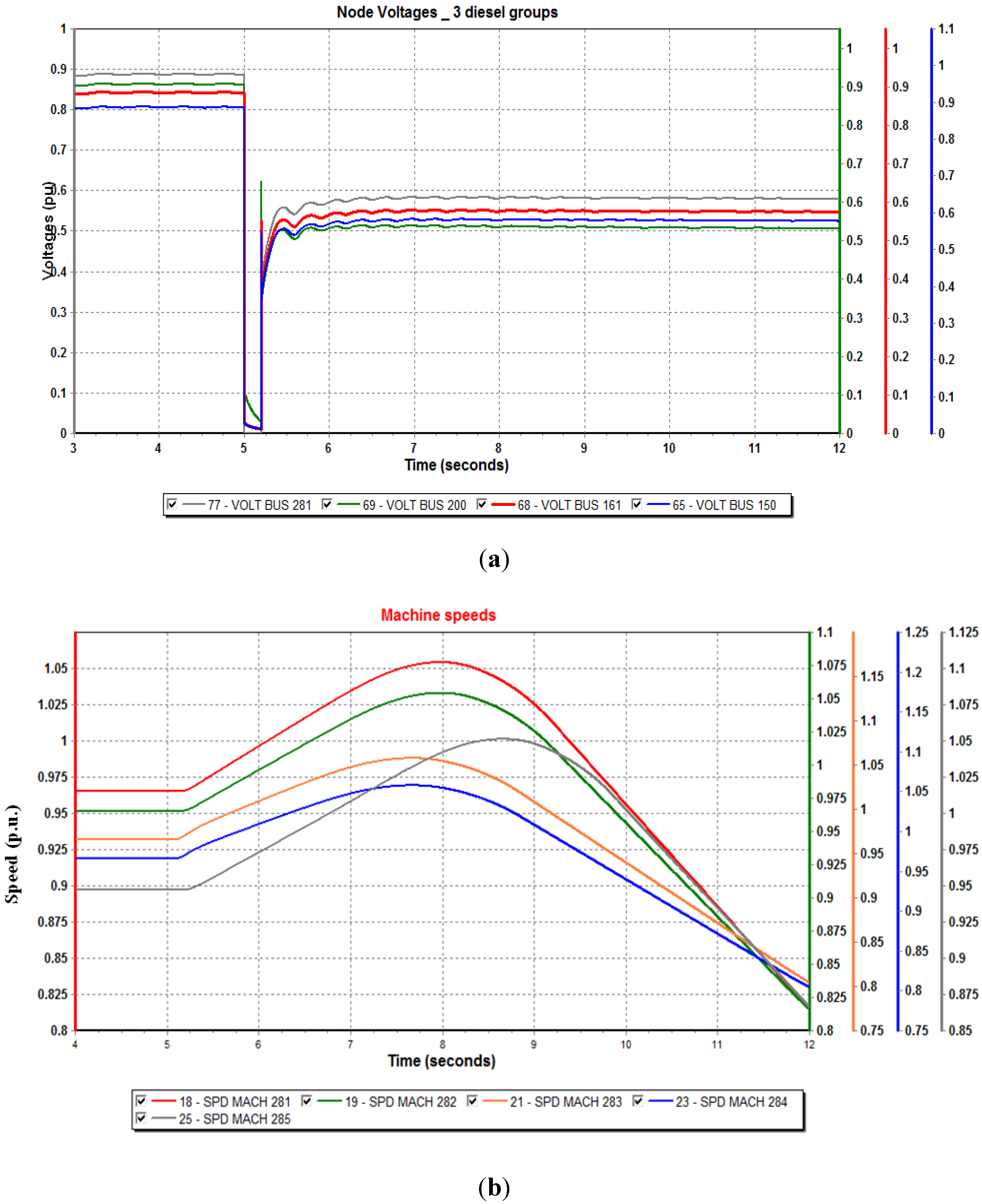
From the application of the Equation (2) to the limit operating case with four diesel units, it is observed that when there is a wind power generation of 11.5 MW the kinetic energy they can provide is 17.33 MJ.
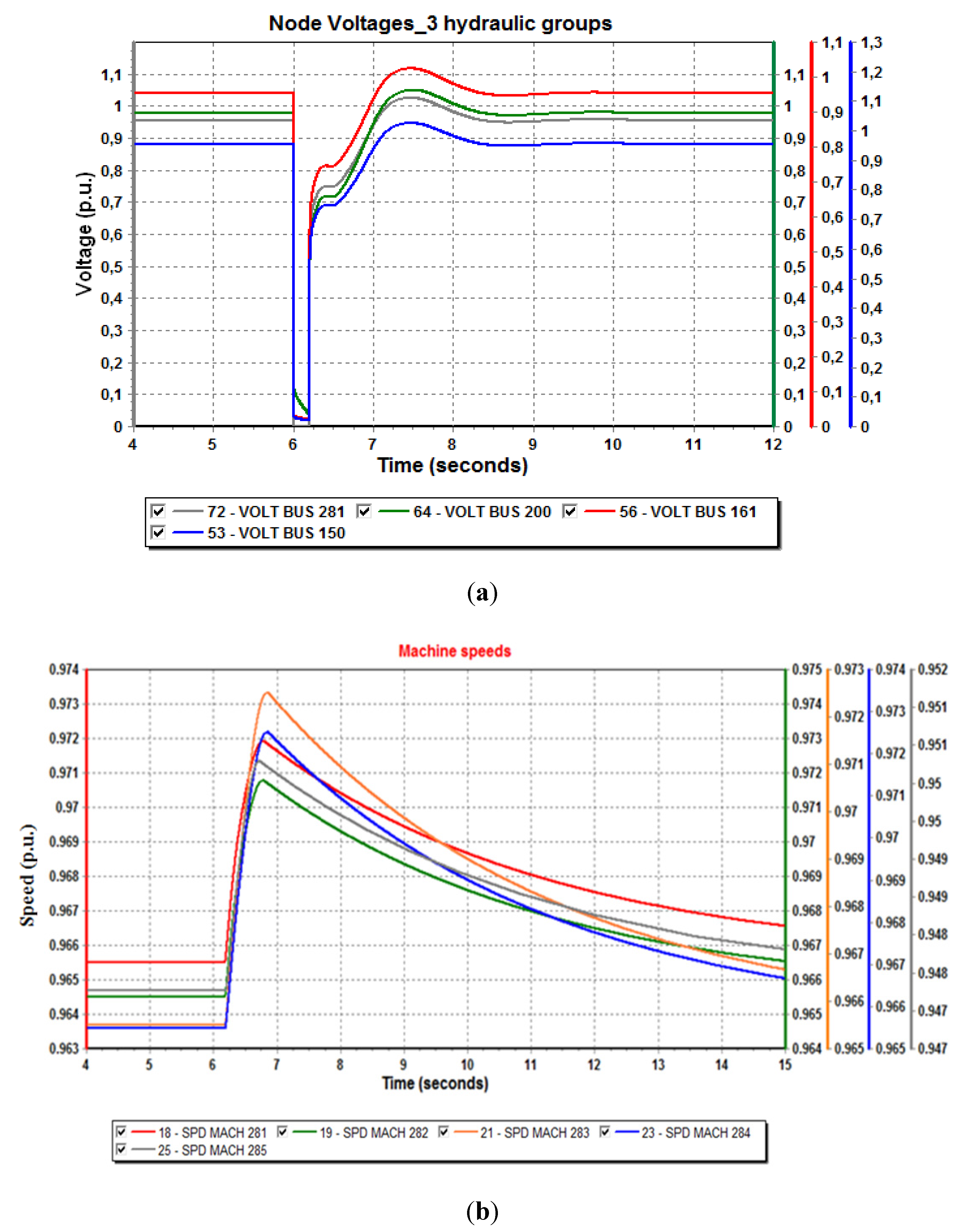
In this case, the four connected groups are equal (numbers 2, 3, 4, and 5). This result is applicable to the hydraulic units scheme. It can also be observed, due to Equation (2), that two Pelton groups would support an inertial rotating energy of 16.64 MJ, an insufficient value to assure stability in case of a severe fault. By using three hydraulic turbines, the kinetic energy they can supply is 24.97 MJ.
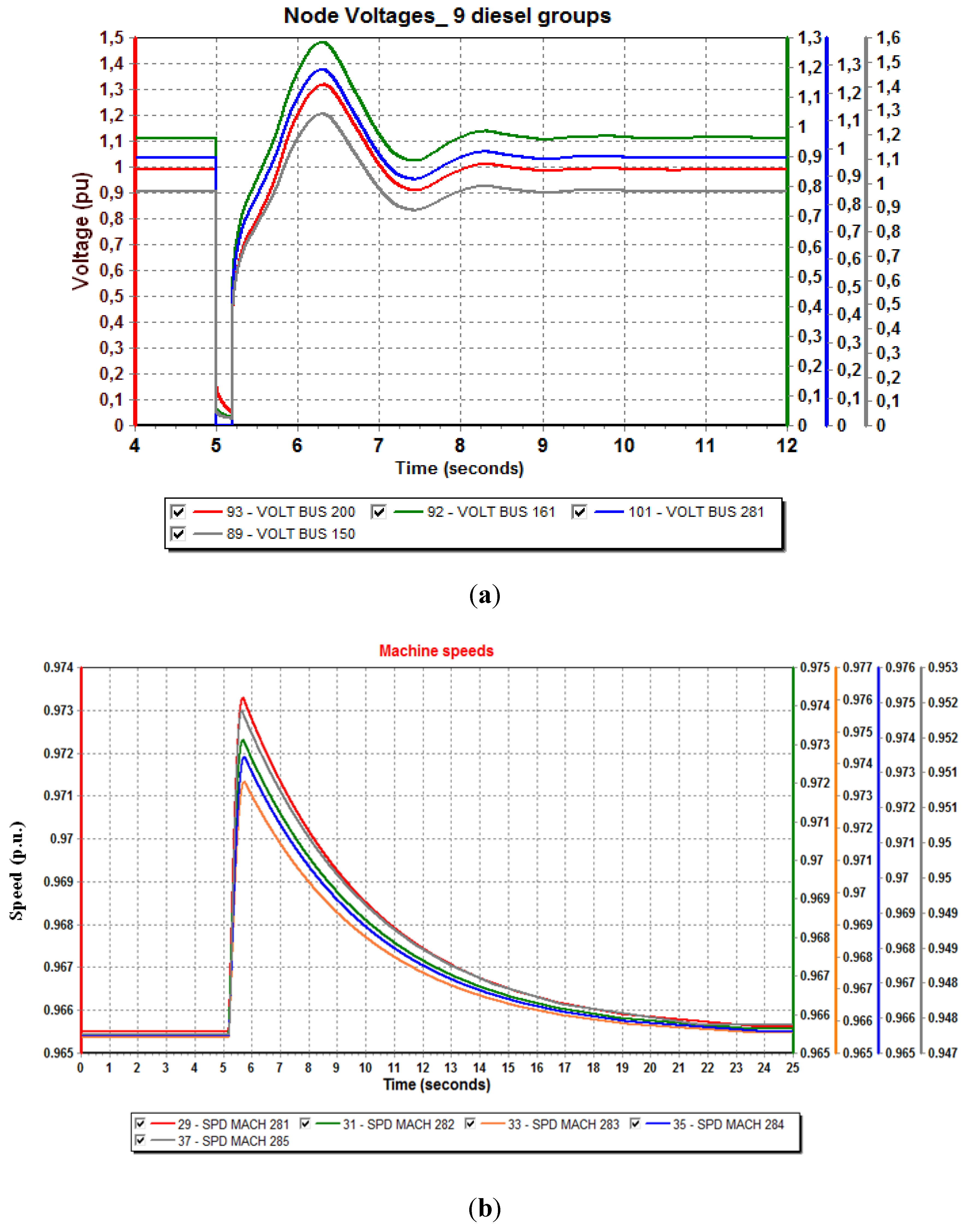
Figure 6.
Bus voltages and machine speeds for a 9-Diesel unit scheme following a wind generator three-phase fault. (a) Node voltages in p.u.; (b) Machine speeds in p.u.
Figure 6.
Bus voltages and machine speeds for a 9-Diesel unit scheme following a wind generator three-phase fault. (a) Node voltages in p.u.; (b) Machine speeds in p.u.
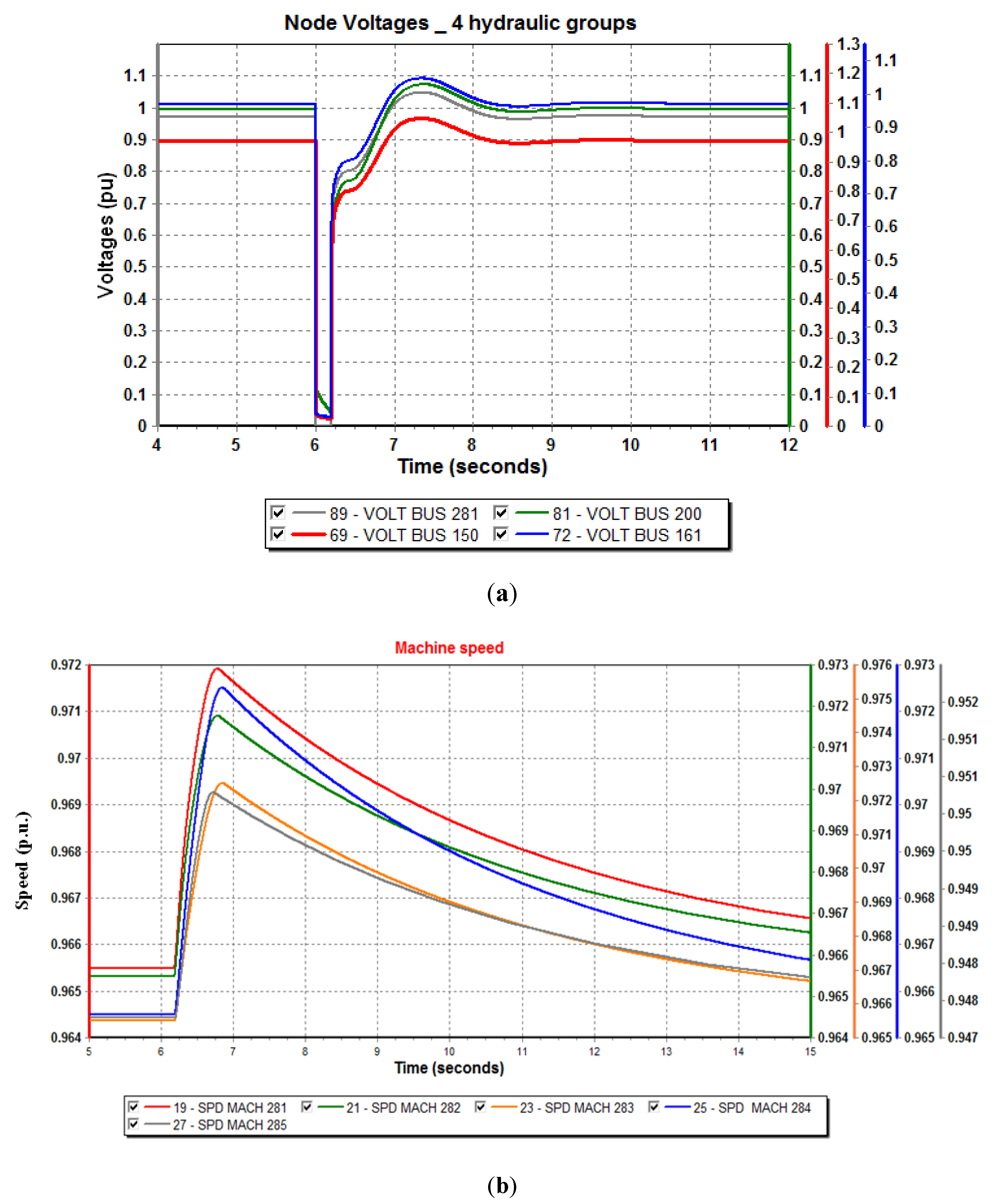
Figure 7.
Bus voltages and machine speeds for a 4-hydraulic unit scheme following a wind generator three-phase fault. (a) Node voltages in p.u.; (b) Machine speeds in p.u.
Figure 7.
Bus voltages and machine speeds for a 4-hydraulic unit scheme following a wind generator three-phase fault. (a) Node voltages in p.u.; (b) Machine speeds in p.u.
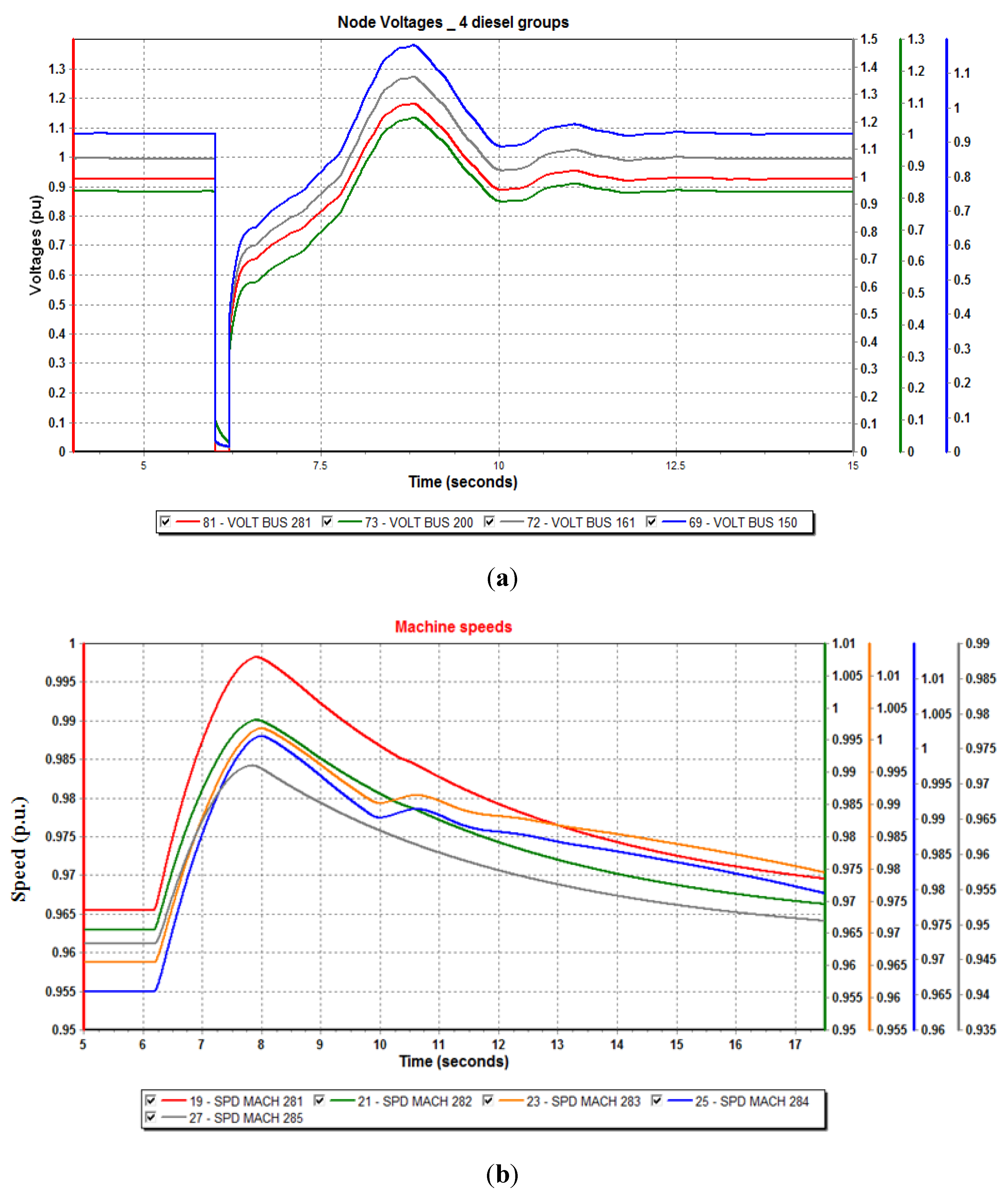
Figure 8.
Bus voltages and machine speeds for a 4-Diesel unit scheme following a wind generator three-phase fault. (a) Node voltages in p.u.; (b) Machine speeds in p.u.
Figure 8.
Bus voltages and machine speeds for a 4-Diesel unit scheme following a wind generator three-phase fault. (a) Node voltages in p.u.; (b) Machine speeds in p.u.
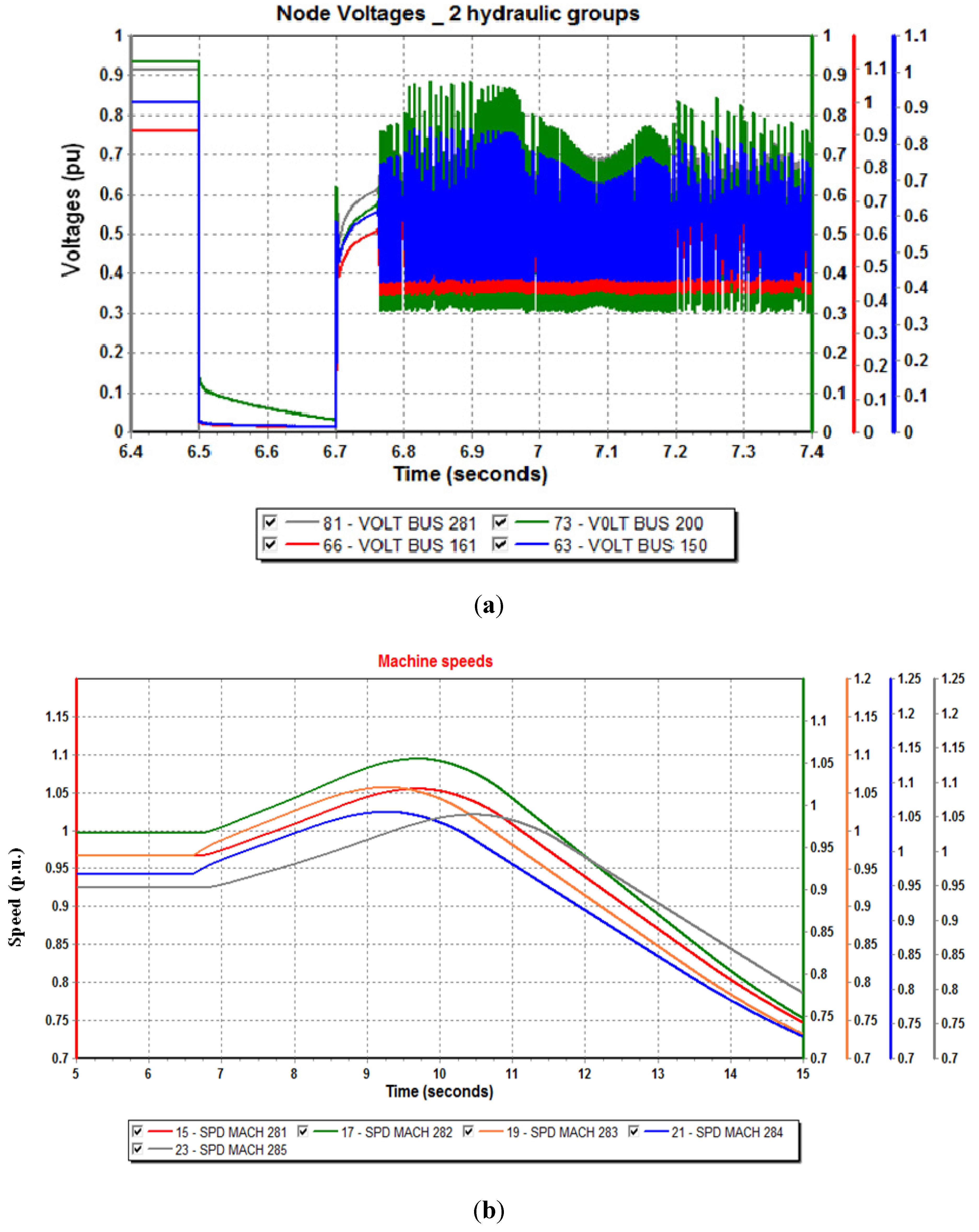
Figure 9.
Bus voltages and machine speeds for a 3-hydraulic unit scheme following a wind generator three-phase fault. (a) Node voltages in p.u.; (b) Machine speeds in p.u.
Figure 9.
Bus voltages and machine speeds for a 3-hydraulic unit scheme following a wind generator three-phase fault. (a) Node voltages in p.u.; (b) Machine speeds in p.u.
Figure 10.
Bus voltages and machine speeds for a 3-Diesel unit scheme following a wind generator three-phase fault. (a) Node voltages in p.u.; (b) Machine speeds in p.u.
Figure 10.
Bus voltages and machine speeds for a 3-Diesel unit scheme following a wind generator three-phase fault. (a) Node voltages in p.u.; (b) Machine speeds in p.u.
Figure 11.
Bus voltages and machine speeds for a 2-hydraulic unit scheme following a wind generator three-phase fault. (a) Node voltages in p.u.; (b) Machine speeds in p.u.
Figure 11.
Bus voltages and machine speeds for a 2-hydraulic unit scheme following a wind generator three-phase fault. (a) Node voltages in p.u.; (b) Machine speeds in p.u.
It can be concluded that three hydraulic turbines in the system can provide more kinetic energy than four diesel units. Apart from that, this solution presents the great advantage that the turbines have a minimum water consumption, just to keep them spinning. The use of hydraulic units is clearly better, cheaper and more respectful to the environment than the use of diesel groups. The excess in inertial rotating mass energy, supplied by the hydraulic groups regarding to the diesel units will result in a reduction of the time required to recover a normal operation point after the clearance of the fault. It is noticeable that, independently of the generating source used, if the number of conventional units is reduced, the time required to recover voltage stability increases, and the recovery slope from the sag becomes more gentle. This statement is proved in the comparison between figures representing the best operating conditions (
Figure 6 and
Figure 7) and their respective cases in the limit operating scenario (
Figure 8 and
Figure 9).
The most important results, deduced from
Figure 6 to
Figure 11, are summarized in
Table 3, to make the comparison easier between voltage levels, over-voltages, slopes, and overspeeds. Recovery time starts at the moment the fault is cleared and ends at the point the voltage level enters into a band of ±5% of the rated voltage value.
Table 3.
Summarized results.
Table 3.
Summarized results.
| Type of conventional source | Number of units | Recovery time (s) | Average overvoltage (%) | Slope (%) | Average overspeed (%) |
|---|
| Diesel | 9 | 3.3 | 20 | 28 | 1 |
| Diesel | 4 | 4.2 | 15 | 16.5 | 2.2 |
| Diesel | 3 | – | – | – | – |
| Hydraulic | 4 | 2.3 | 6.5 | 27.3 | 2.1 |
| Hydraulic | 3 | 2.6 | 4.3 | 22 | 1.8 |
| Hydraulic | 2 | – | – | – | – |
The results show that, to ensure system stability in the worst network contingency, the best option is to hold three hydraulic units in spinning reserve mode, without water in the chamber, as free wheels. This option offers clear advantages over the alternative of keeping some diesel generators connected: first, the overvoltage produced with hydraulic units is lower than with Diesel ones; second, hydraulic units have a faster frequency recovery time; and finally, spinning hydraulic machines do not consume fuel. Thereby, the feasibility of a reliable, secure, and environmentally friendly system using the hydraulic turbines as synchronous compensators is demonstrated [
19].


 ,
, 


