Energy Storage System with Voltage Equalization Strategy for Wind Energy Conversion

Abstract
:1. Introduction
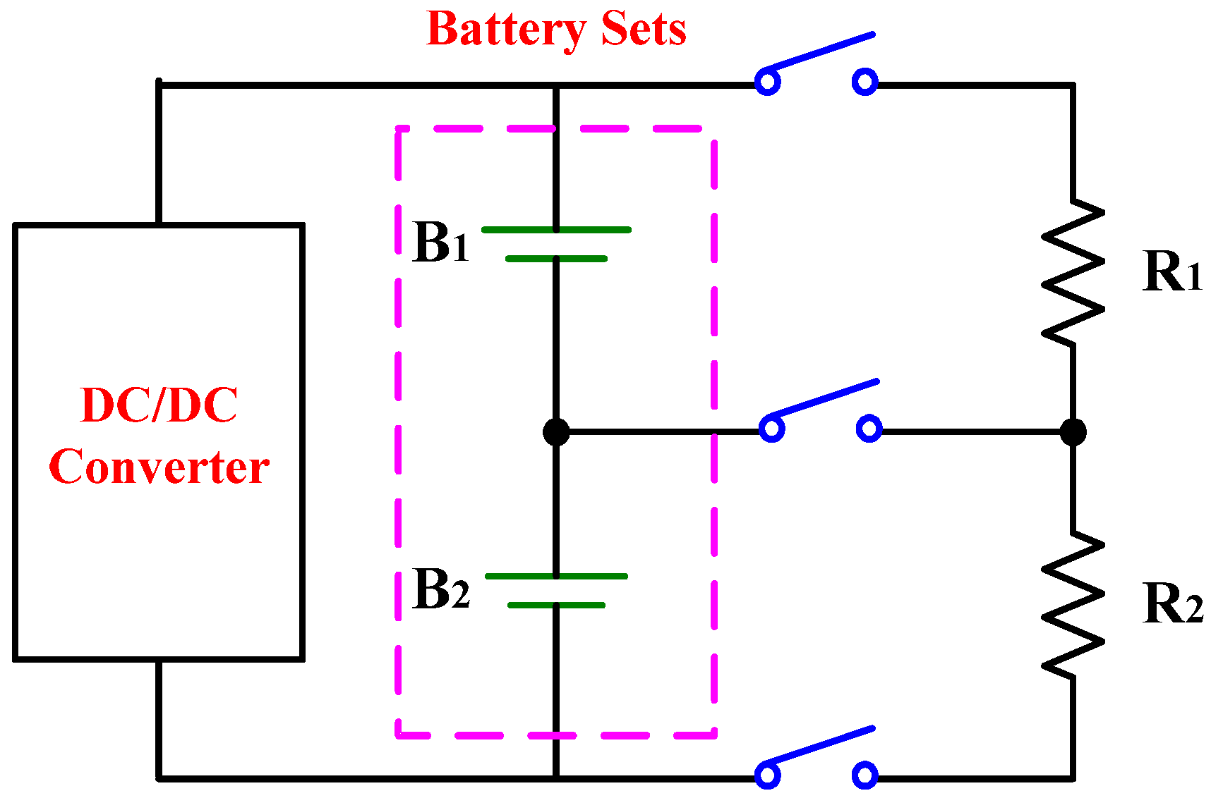
- (1)
- Dissipative shunting resistor,
- (2)
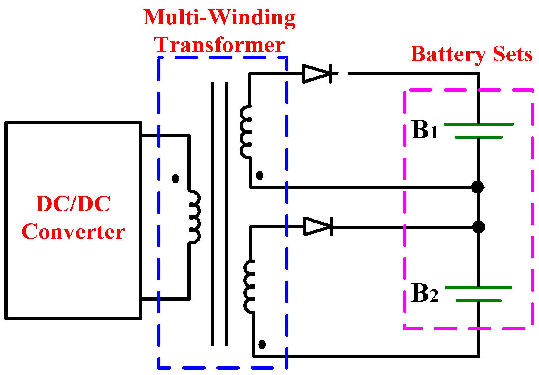
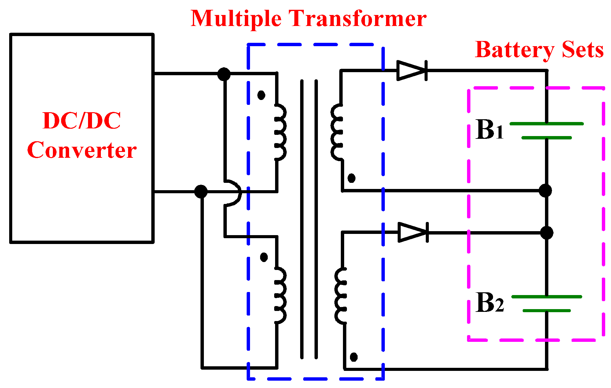
- Multi-winding transformer, and
- (3)
- Multiple transformers.


2. Operational Principles

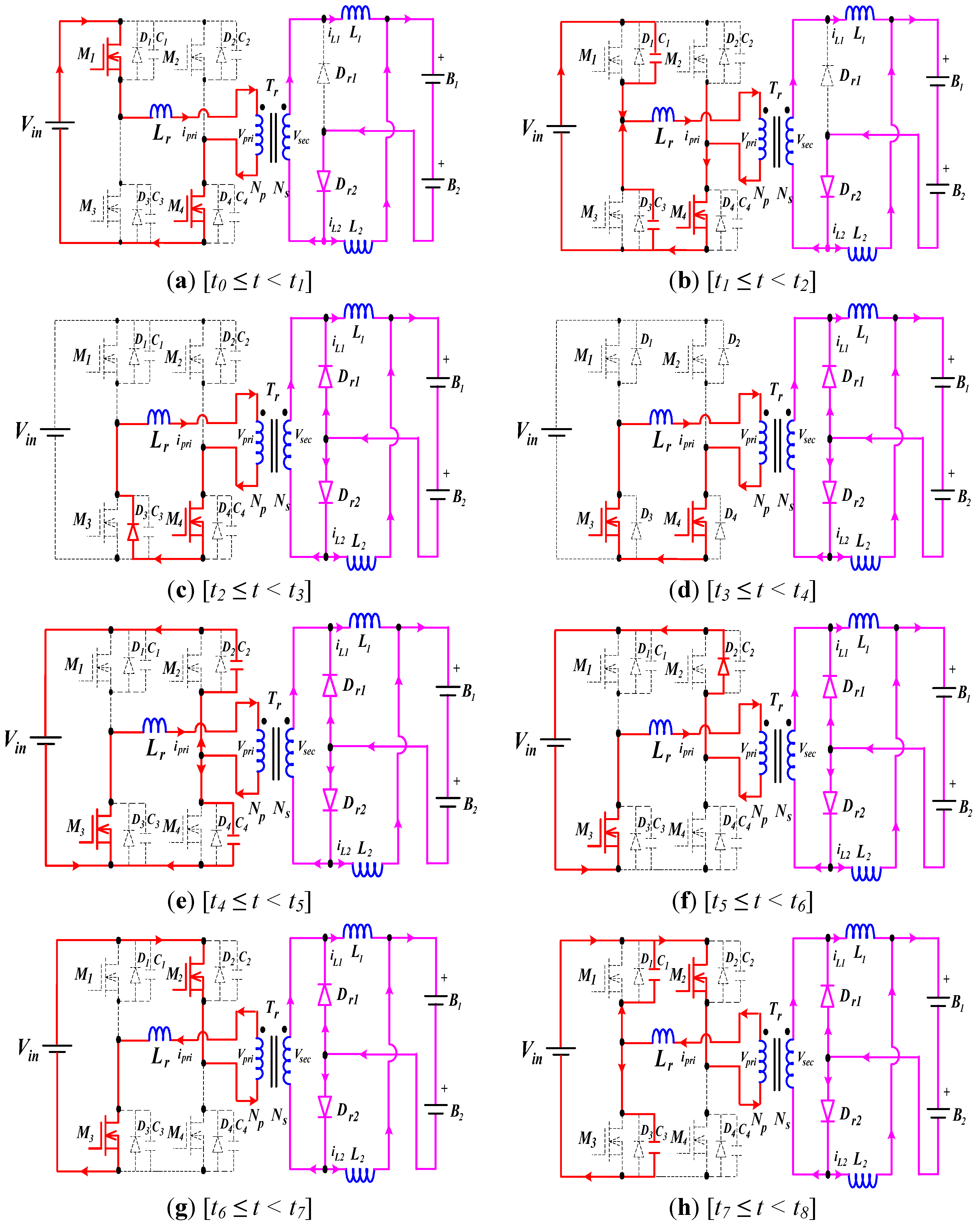
- (1)
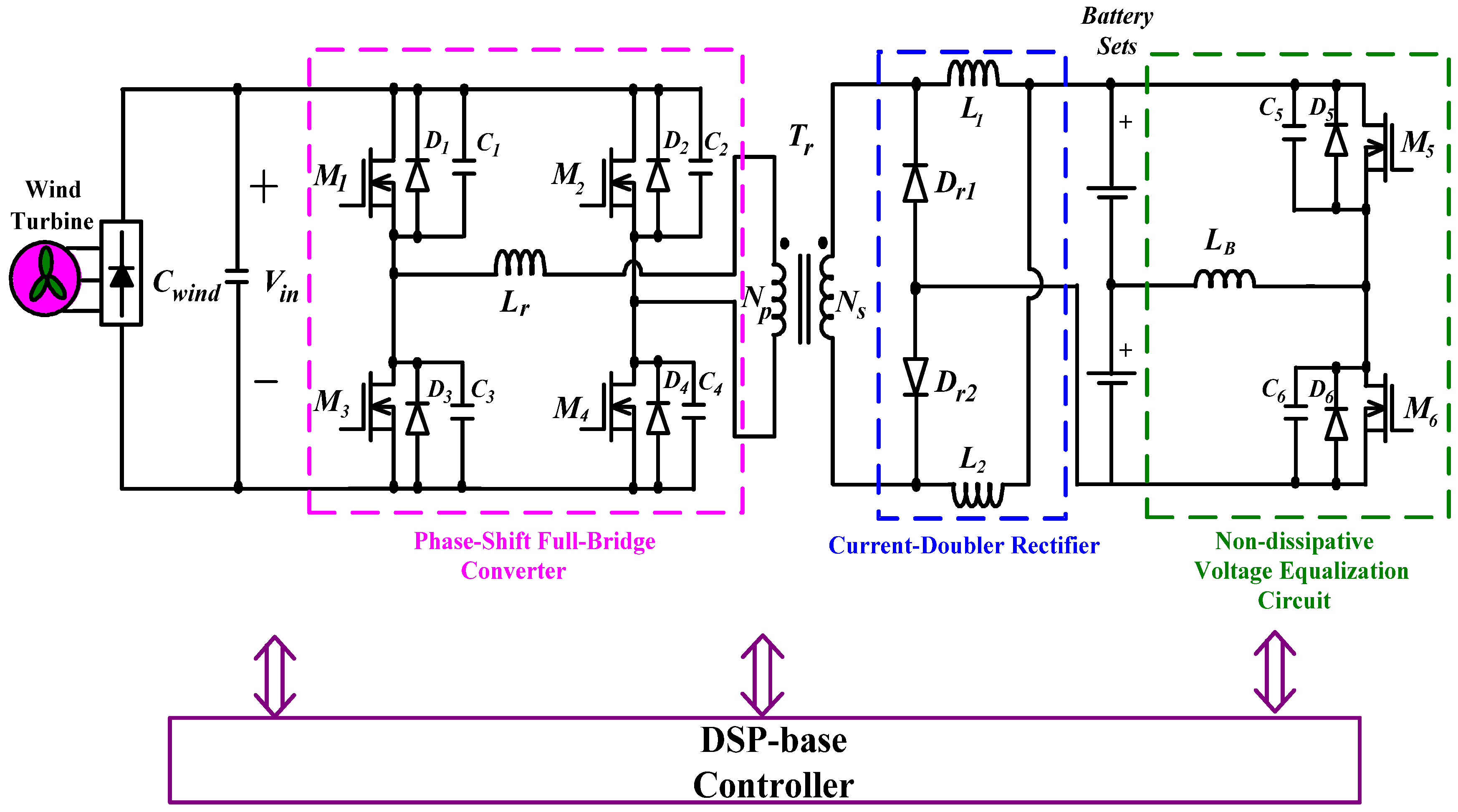
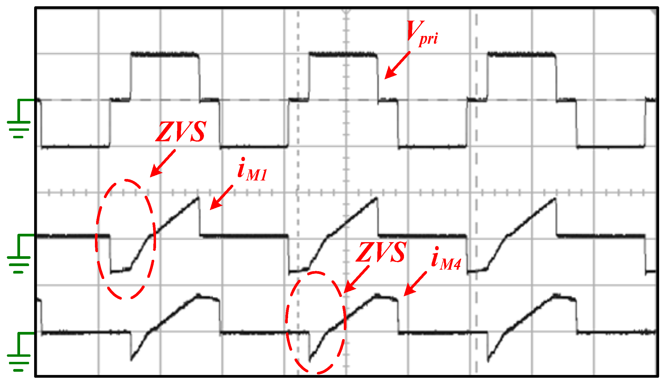
- To achieve ZVS feature for all power switches of full-bridge converter, the extra resonant inductor (Lr) is usually required.
- (2)
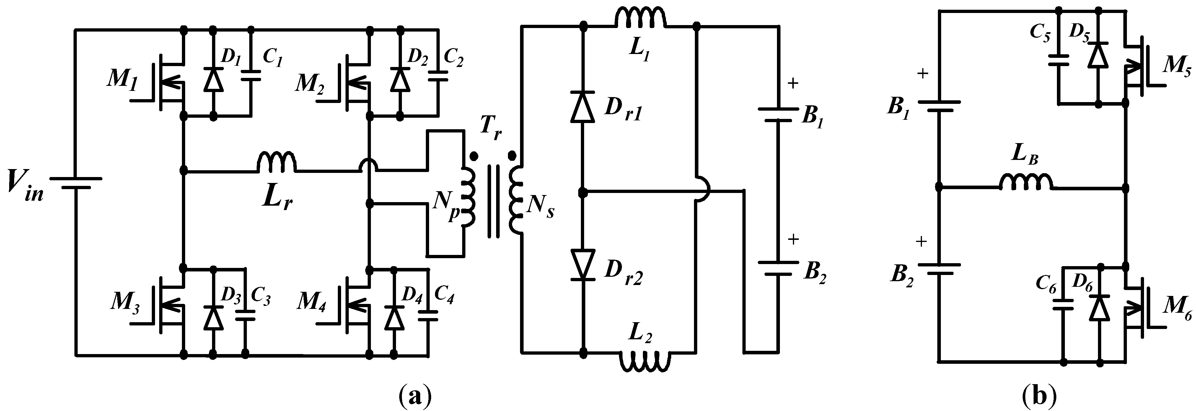
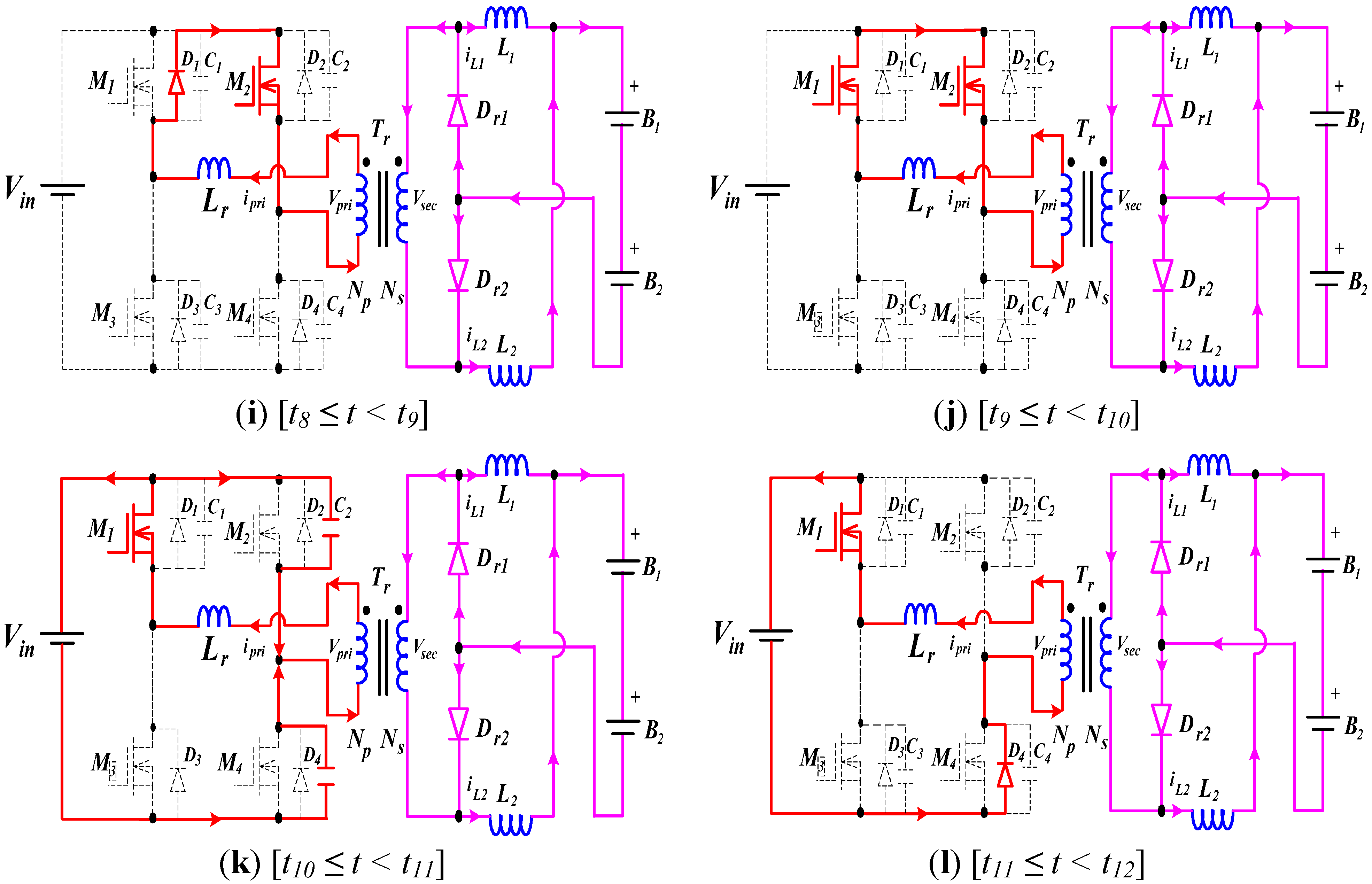
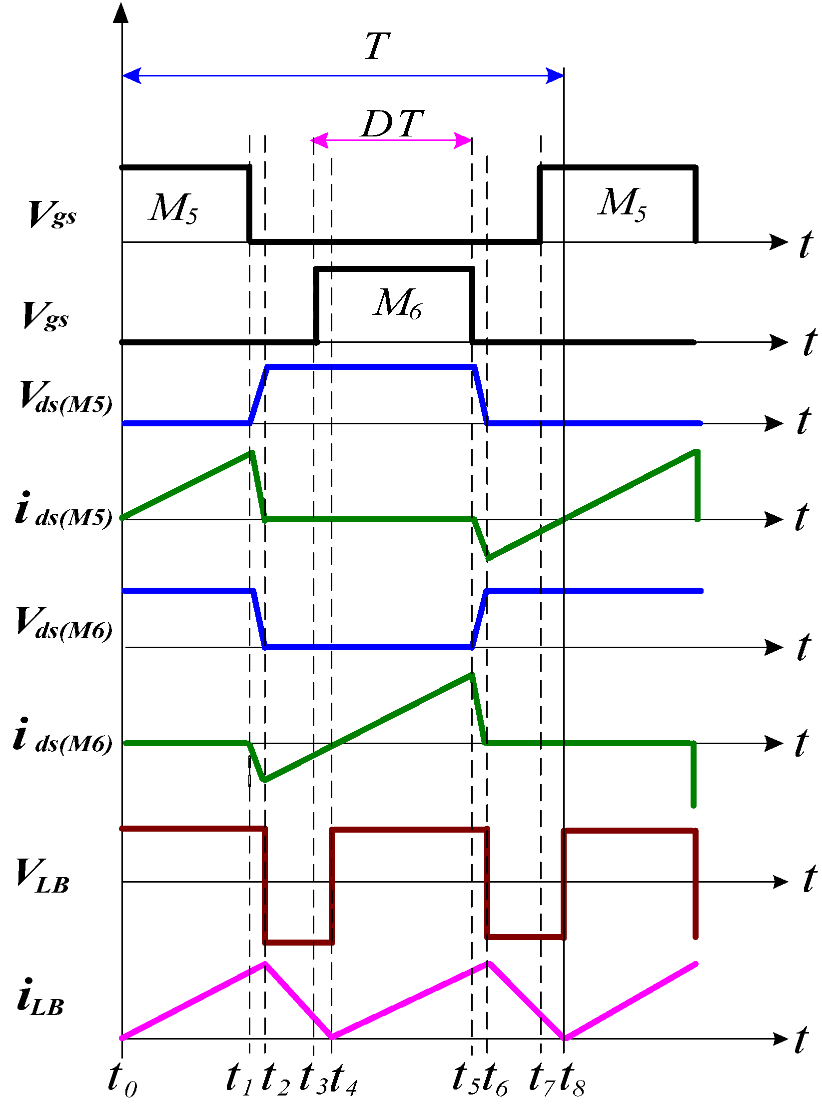
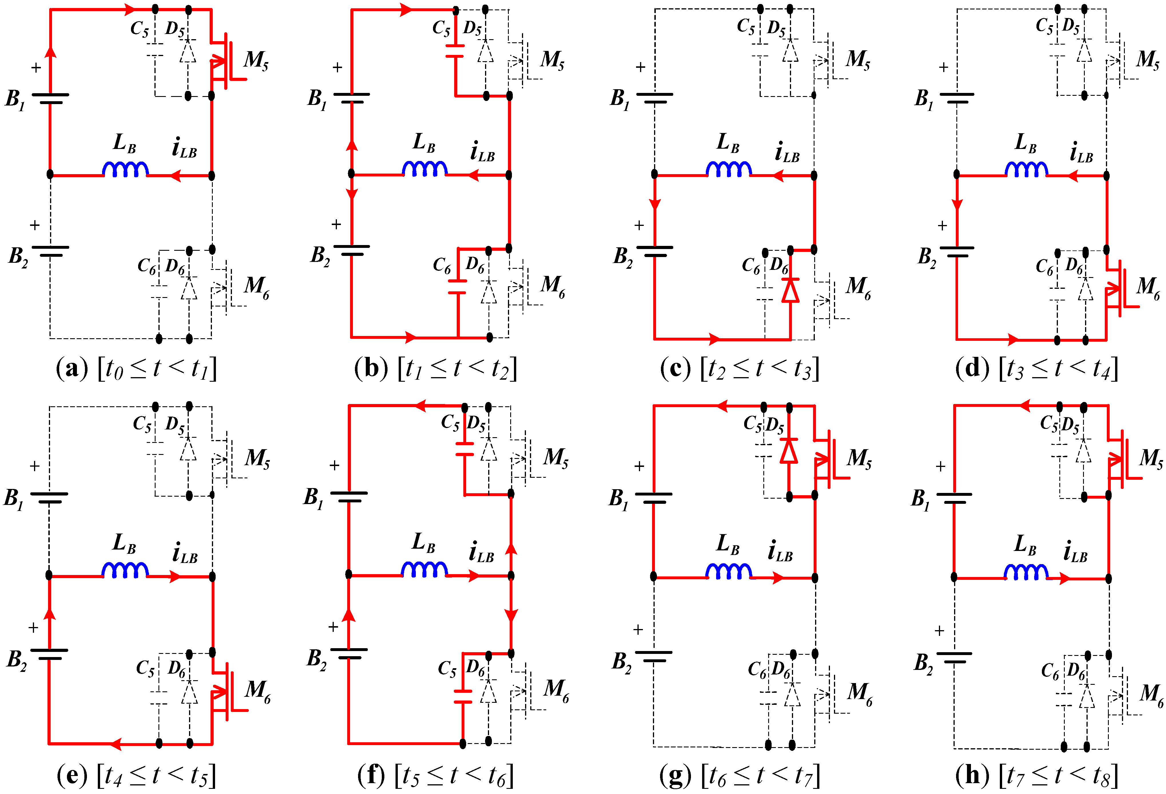
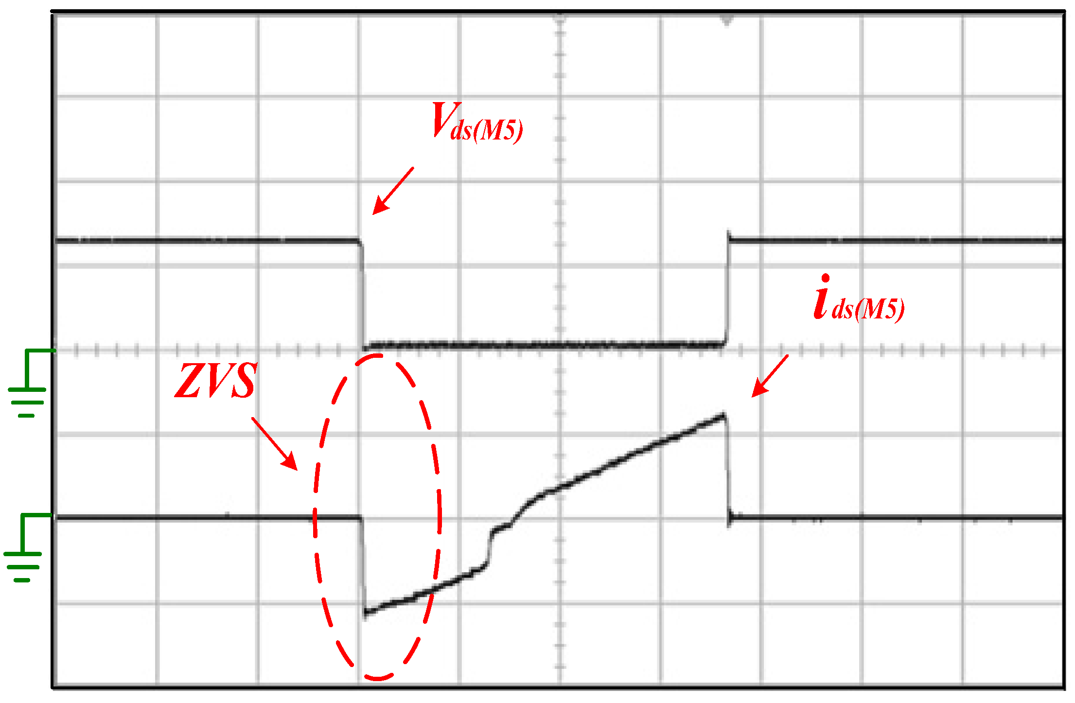
- To analyze the ZVS feature of all power switches (M1, M2, M3, M4, M5 and M6), their body diodes (D1, D2, D3, D4, D5 and D6) and parasitic capacitors (C1, C2, C3, C4, C5 and C6) will be considered at the steady-state operation of the circuit.
2.1. Operational Principles of Charging Mode

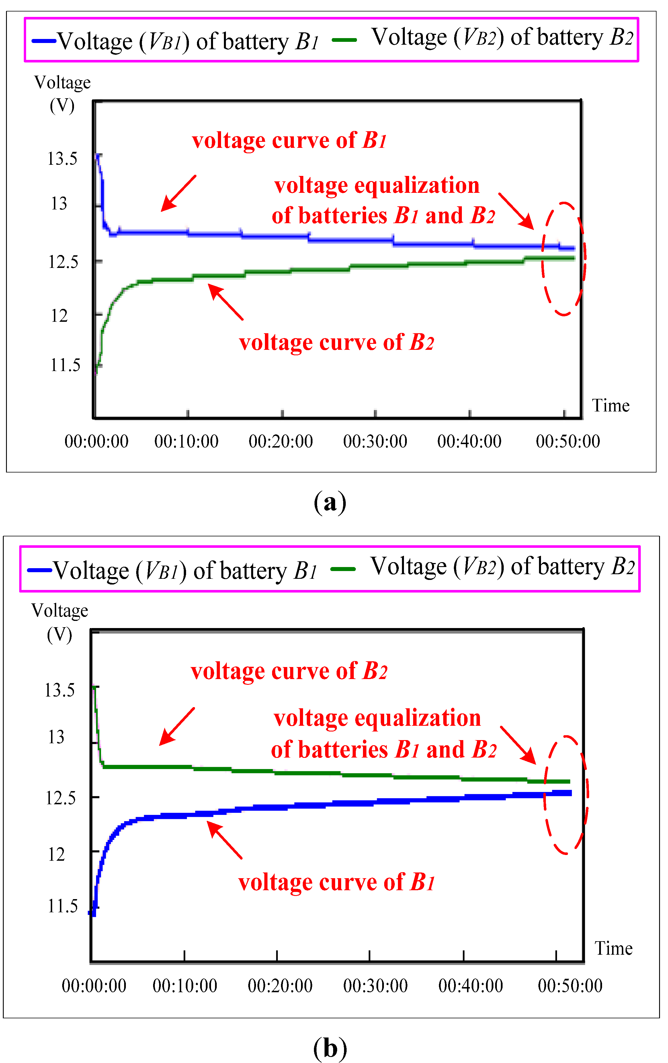
2.2. Operational Principles of Voltage Equalization Mode


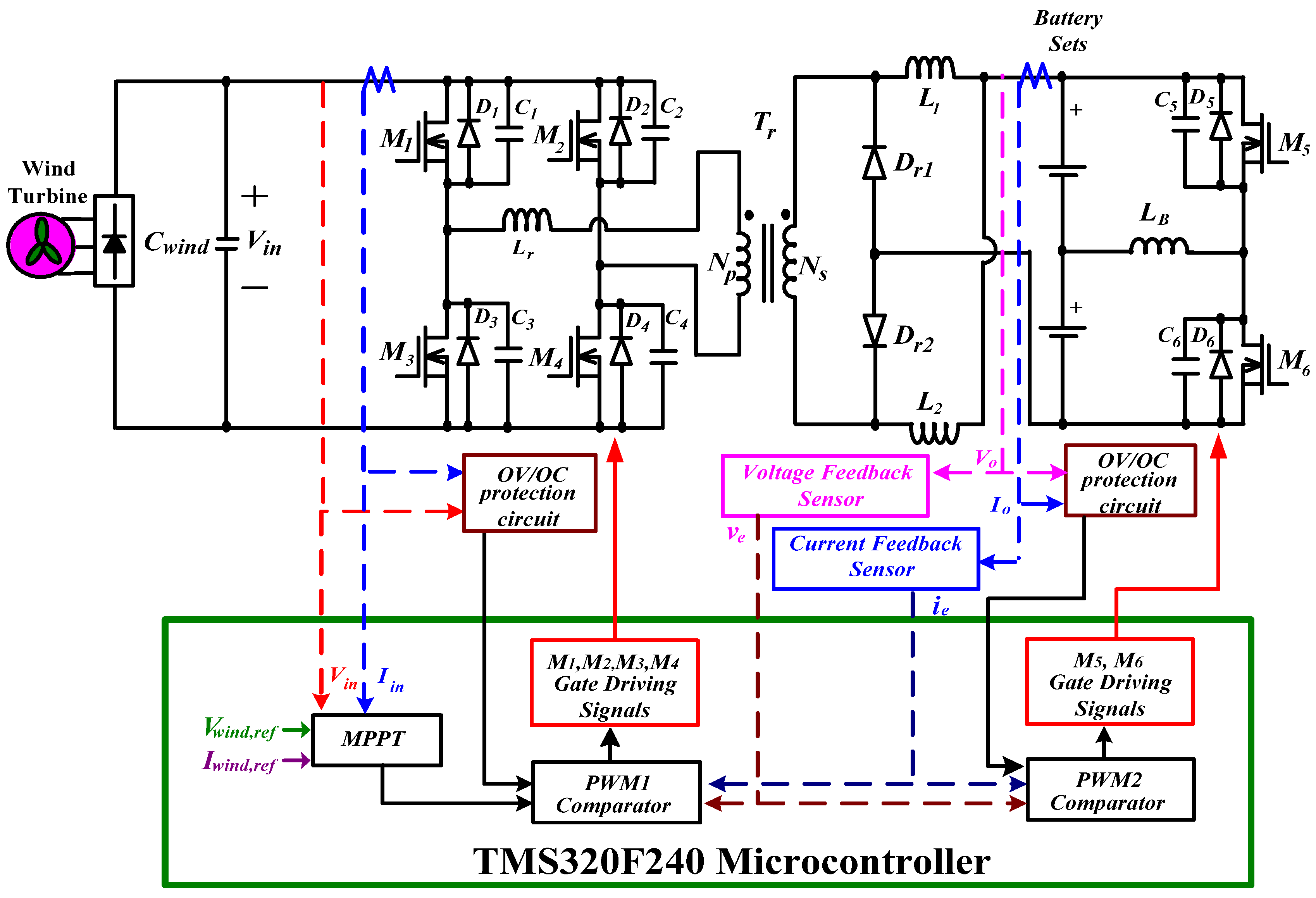
3. Control Scheme
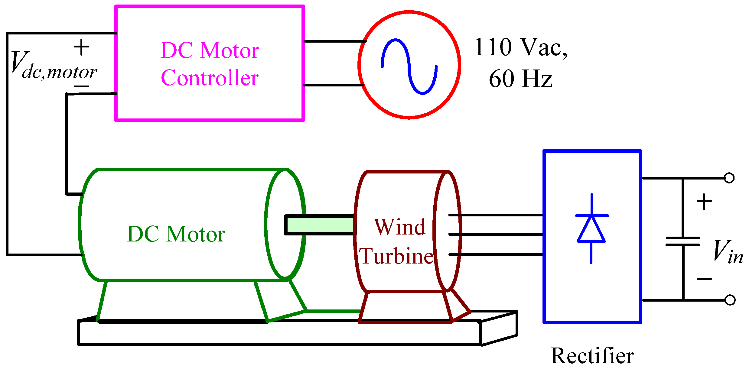
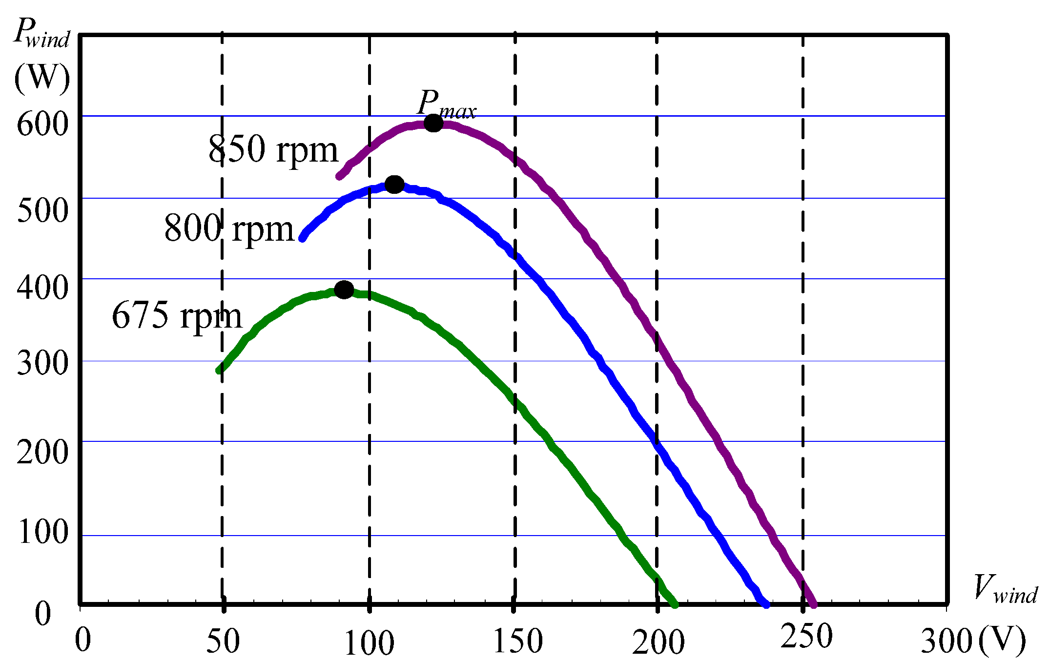
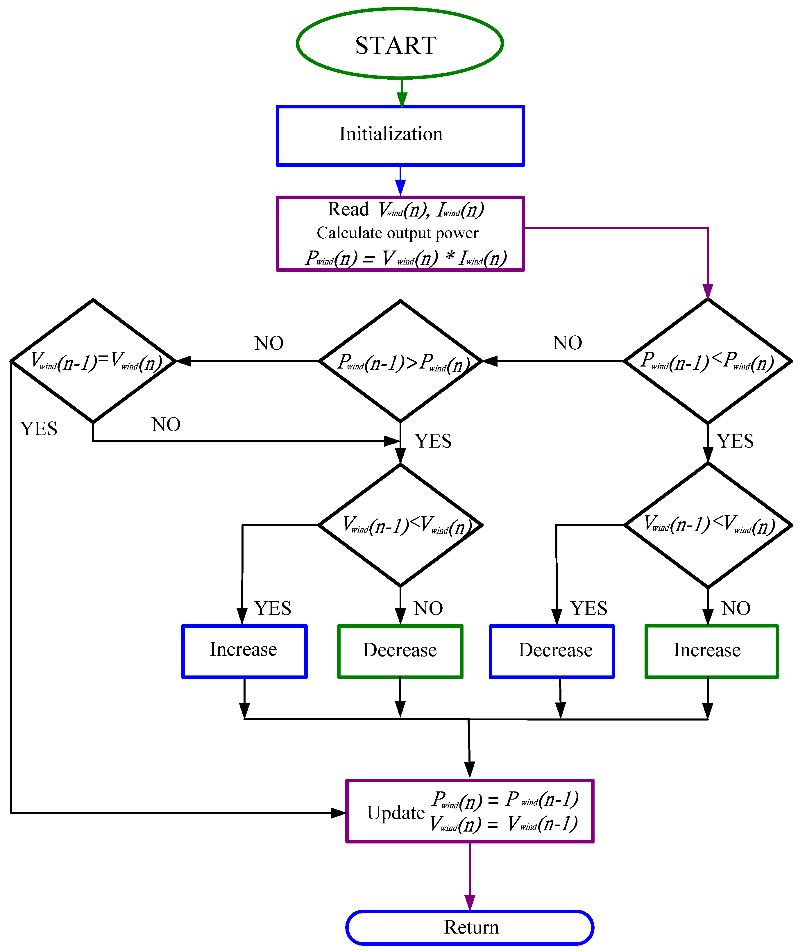
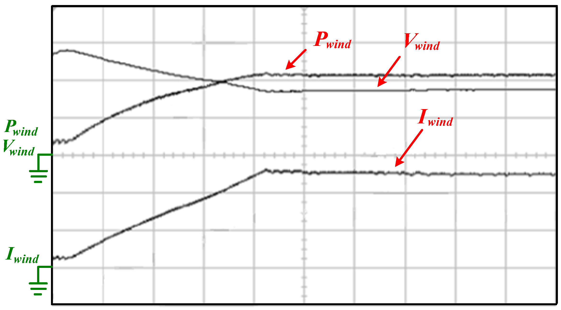
3.1. Wind Turbine MPPT Algorithm


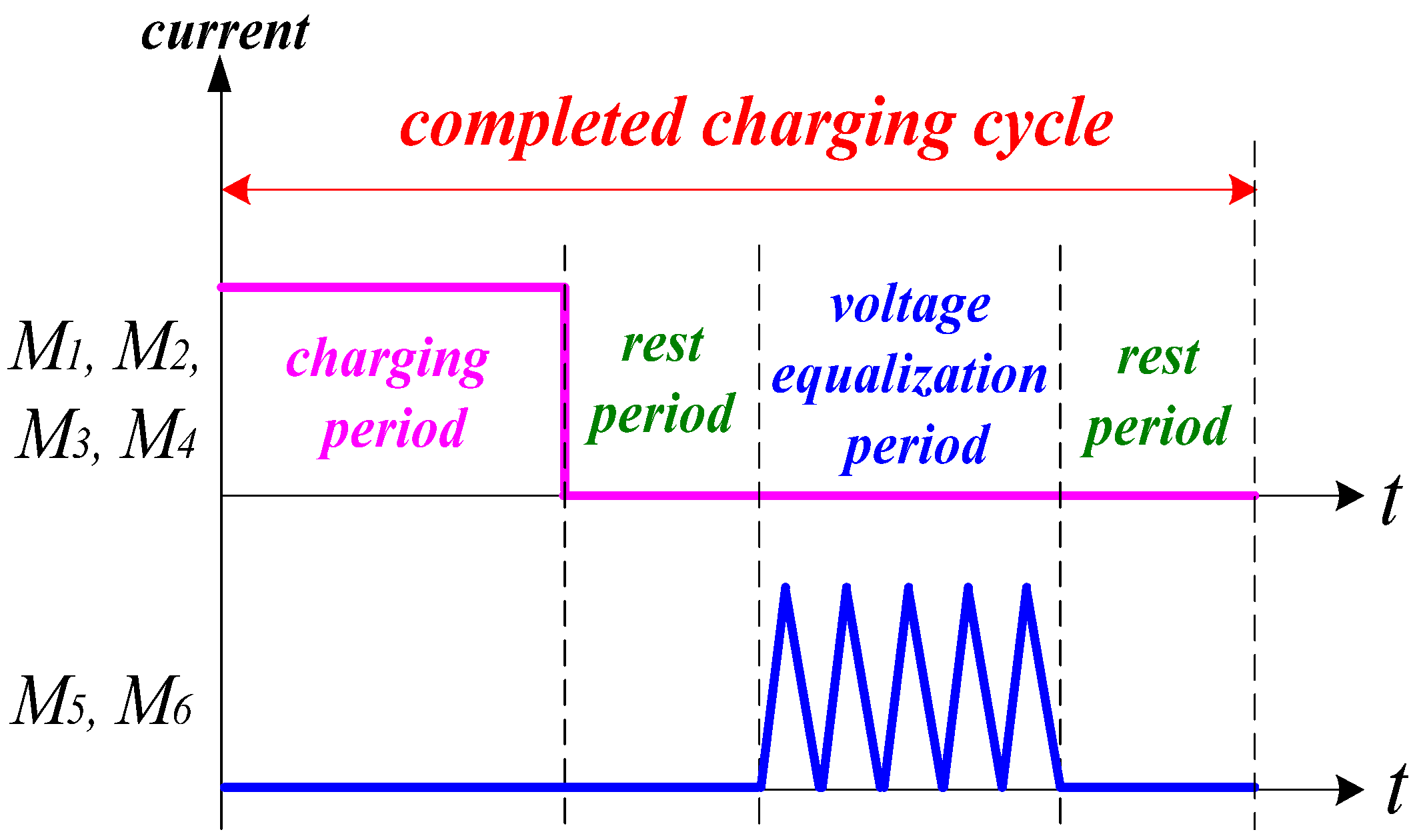
3.2. Control Strategy of Voltage Equalization
3.3. Protection Circuits

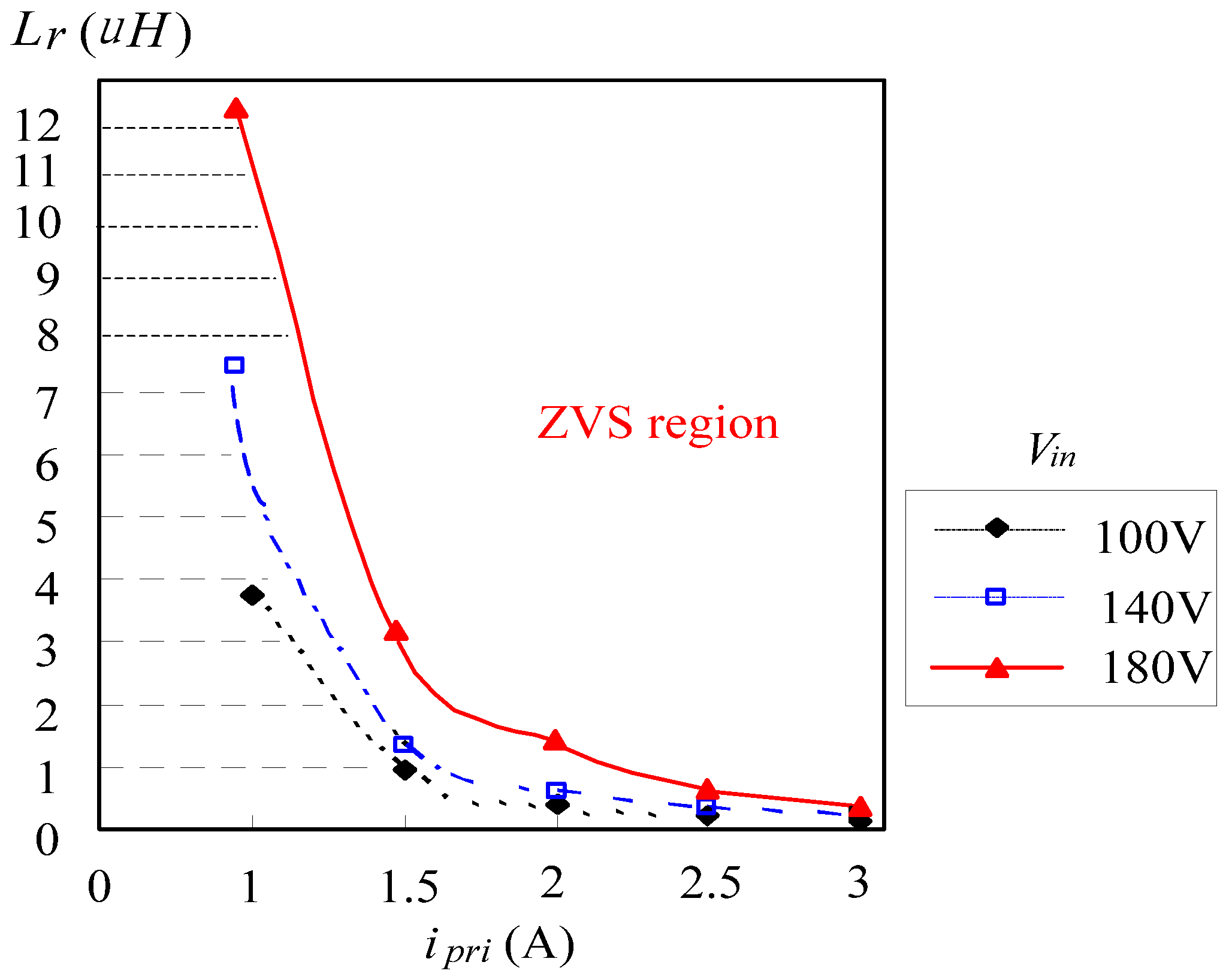
3.4. Condition of ZVS

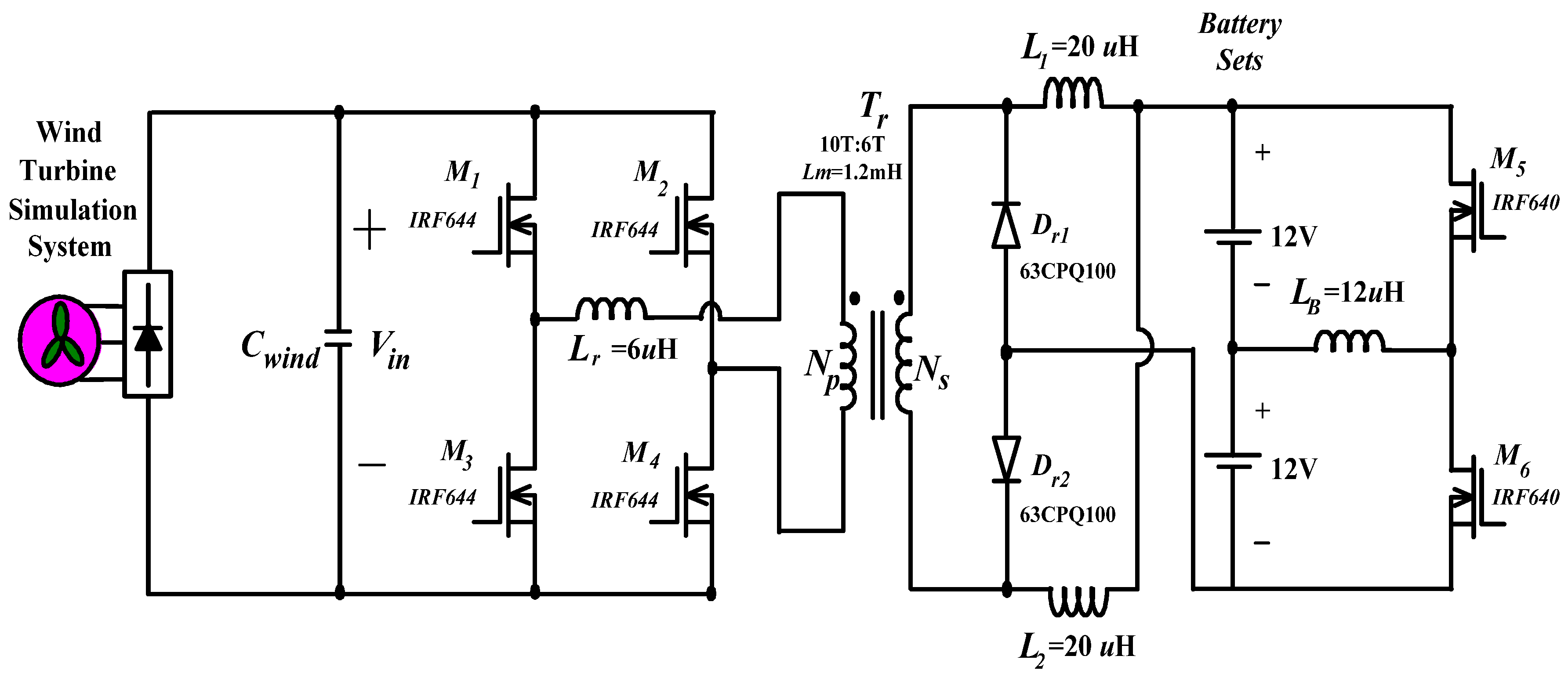
4. Experimental Results
- (1)
- Input voltage: Vin = 80~180 Vdc;
- (2)
- Output voltage of series batteries: Vout = 24 Vdc;
- (3)
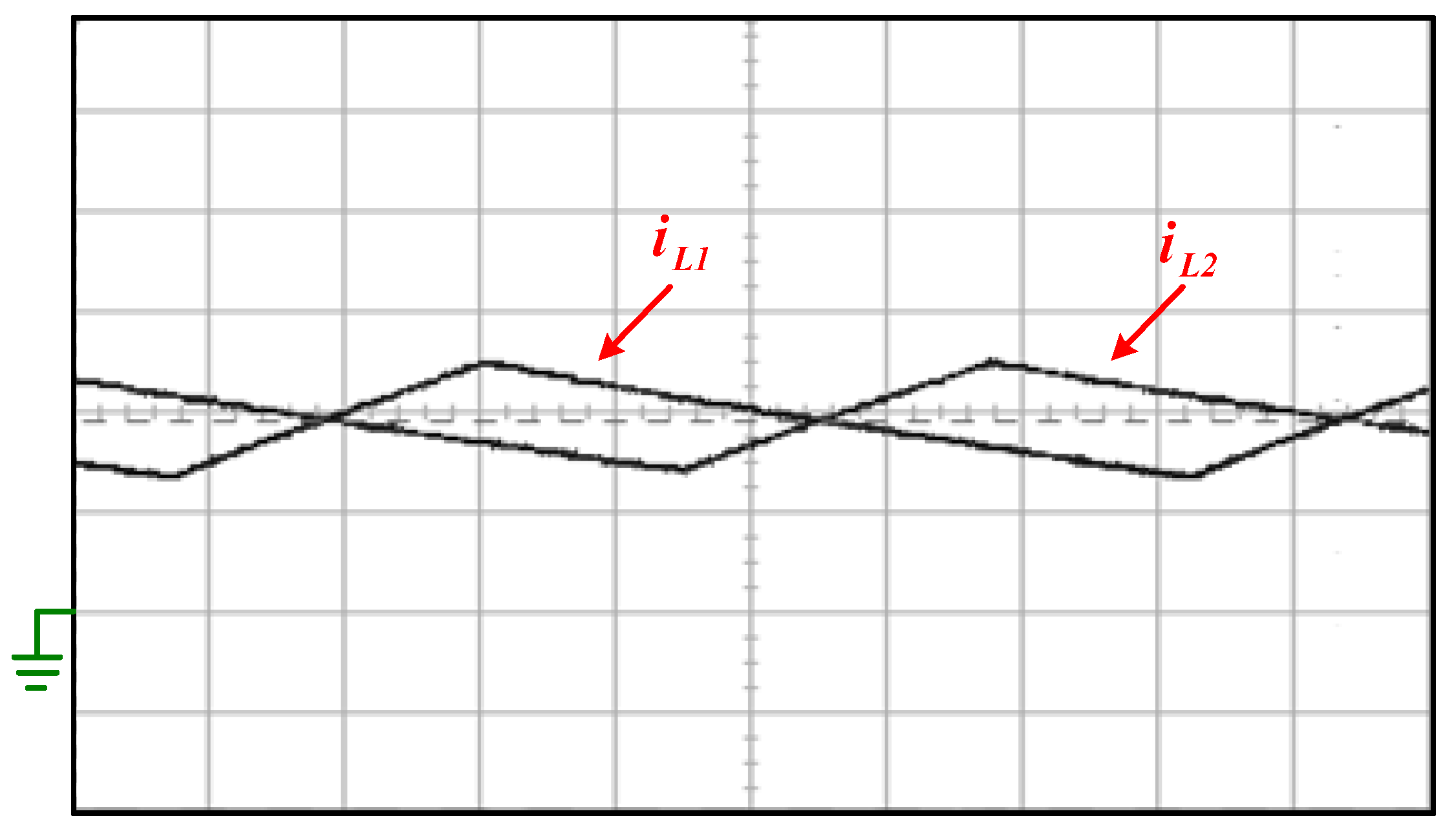
- Maximum charging current of series batteries: iB = iL1 + iL2 = 20 A;
- (4)
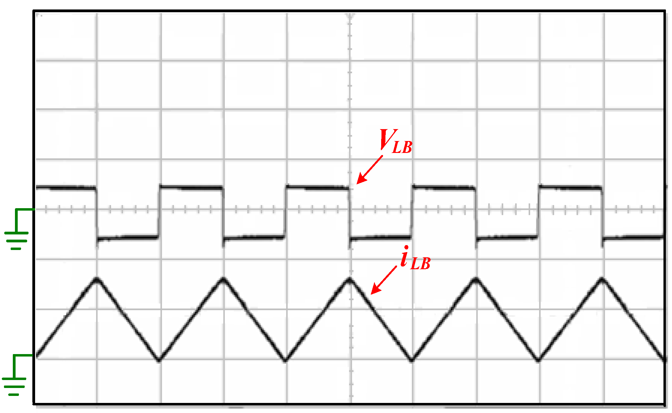
- Discharging current of series batteries: iLB = 10 A;
- (5)
- Inductors L1 and L2 = 20 µH, LB = 12 µH;
- (6)
- Resonant Inductors Lr = 6 µH;
- (7)
- Switching frequency: fs = 50 kHz (M1~M6).


5. Conclusions
References
- Bull, S.R. Renewable energy today and tomorrow. Proc. IEEE 2001, 89, 1216–1226. [Google Scholar] [CrossRef]
- World Wind Energy Association. World Wind Energy Report 2008. Available online: http://www.wwindea.org/home/images/stories/worldwindenergyreport2008_s.pdf (accessed on 2 July 2012).
- Robinson, J.; Jovcic, D.; Joos, G. Analysis and design of an offshore wind farm using a MV dc grid. IEEE Trans. Power Deliv. 2010, 25, 2164–2173. [Google Scholar] [CrossRef]
- O'Donnell, R.; Schofield, N.; Smith, A.C.; Cullen, J. Design Concepts for High-Voltage Variable-Capacitance DC Generators. IEEE Trans. Ind. Appl. 2009, 45, 1778–1784. [Google Scholar] [CrossRef]
- Rahimi, M.; Parniani, M. Efficient control scheme of wind turbines with doubly fed induction generators for low-voltage ride-through capability enhancement. Renew. Power Gener. 2010, 4, 242–252. [Google Scholar] [CrossRef]
- Teleke, S.; Baran, M.E.; Huang, A.Q.; Bhattacharya, S.; Anderson, L. Control Strategies for Battery Energy Storage for Wind Farm Dispatching. IEEE Trans. Energy Convers. 2009, 24, 725–731. [Google Scholar] [CrossRef]
- Kuo, Y.C.; Liang, T.J.; Chen, J.F. Novel maximum-power-point-tracking controller for photovoltaic energy conversion system. IEEE Trans. Ind. Electron. 2001, 48, 594–601. [Google Scholar] [CrossRef]
- Koyanagi, A.; Nakamura, H.; Kobayashi, M.; Suzuki, Y.; Shimada, R. Study on maximum power point tracking of wind turbine generator using a flywheel. Proc. Power Convers. 2002, 1, 322–327. [Google Scholar]
- Amei, K.; Takayasu, Y.; Ohji, T.; Sakui, M. A maximum power control of wind generator system using a permanent magnet synchronous generator and a boost chopper circuit. Proc. Power Convers. 2002, 3, 1447–1452. [Google Scholar]
- Patel, H.; Agarwal, V. MPPT Scheme for a PV-Fed Single-Phase Single-Stage Grid-Connected Inverter Operating in CCM with Only One Current Sensor. IEEE Trans. Energy Convers. 2009, 24, 256–263. [Google Scholar] [CrossRef]
- Moore, S.W.; Schneider, P.J. A Review of Cell Equalization Methods for Lithium Ion and Lithium Polymer Battery System. In Proceedings of Society of Automotive Engineers 2001 World Congress, Detroit, MI, USA, March 2001.
- Cao, J.; Schofield, N.; Emadi, A. Battery Balancing Methods: A Comprehensive Review. In Proceedings of IEEE Vehicle Power and Propulsion Conference, Harbin, China, September 2008.
- Cho, J.G.; Baek, J.W.; Jeong, C.Y.; Rim, G.H. Novel Zero-Voltage and Zero- Current-Switching Full Bridge PWM Converter Using Transformer Auxiliary Winding. IEEE Trans. Power Electron. 2000, 15, 250–257. [Google Scholar] [CrossRef]
- Lee, Y.S.; Chen, G.T. Bi-directional DC-to-DC Converter Application in Battery Equalization for Electric Vehicles. In Proceedings of IEEE Power Electronics Specialists Conference, Aachen, Germany, June 2004; pp. 2766–2772.
- Lee, Y.S.; Chen, M.W; Hsu, K.L.; Du, J.Y.; Chuang, C.F. Cell Equalization Scheme with Energy Transferring Capacitance for series connected battery strings. In Proceedings of IEEE Region 10 Technical Conference on Computers, Communications, Control and Power Engineering (IEEE TENCON’02), Beijing, China, October 2002; pp. 2042–2045.
© 2012 by the authors; licensee MDPI, Basel, Switzerland. This article is an open-access article distributed under the terms and conditions of the Creative Commons Attribution license (http://creativecommons.org/licenses/by/3.0/).
Share and Cite
Tsai, C.-T. Energy Storage System with Voltage Equalization Strategy for Wind Energy Conversion. Energies 2012, 5, 2331-2350. https://doi.org/10.3390/en5072331
Tsai C-T. Energy Storage System with Voltage Equalization Strategy for Wind Energy Conversion. Energies. 2012; 5(7):2331-2350. https://doi.org/10.3390/en5072331
Chicago/Turabian StyleTsai, Cheng-Tao. 2012. "Energy Storage System with Voltage Equalization Strategy for Wind Energy Conversion" Energies 5, no. 7: 2331-2350. https://doi.org/10.3390/en5072331
APA StyleTsai, C.-T. (2012). Energy Storage System with Voltage Equalization Strategy for Wind Energy Conversion. Energies, 5(7), 2331-2350. https://doi.org/10.3390/en5072331