1. Introduction
Power companies must continually improve the reliability of power supply and customer satisfaction through the enhancement of service quality. To these ends, the Taiwan Power Company (Taipower) has focused on the distribution feeder automation system (DFAS). The DFAS integrates computers, communications, and control technology into distribution systems. It is composed of control center facilities, feeder remote terminal units (FRTUs), feeder terminal units (FTUs), overhead/underground automatic line switches, and communication systems. Automatic line switches are being installed in the DFAS to replace traditional ones. Under normal conditions, the voltage and current information of the automatic line switches are collected and sent to the control center. When a fault occurs, the automatic line switches will isolate the fault and restore service functions as commanded by the control center, thus effectively improving the power quality.
Few papers focus only on the application of automatic line switches in DFAS, but no attempts have been made to address the coordination issues involved. To improve the cost effectiveness of the distribution automation system, Chen
et al. proposed an immune algorithm to determine the optimal location of automatic line switches [
1]. Ho
et al. examined the application of an immune algorithm to determine the optimal location of fault indicators in distribution systems. The fault indicators are then coordinated with line switches after they are installed at their optimal locations [
2]. Chen
et al. use artificial neural network to derive the unit commitment of automatic line switches for distribution automation systems [
3]. There are some other researches on DFAS. Seol
et al. [
4] developed a protection coordination program for a distribution automation system for the Korea Electric Power Corporation. This program provides optimal operation in the distribution network, and can examine the validity of the settings of protection facilities by comparing them to the time current curves (TCCs). An efficient and reliable method for fault isolation and service restoration through shifting of the feeder tie switches in ungrounded systems has also been proposed [
5]. Lin
et al. developed a multiagent-based distribution automation system for the restoration of service in distribution systems following a fault. Typical distribution system configurations employed by Taipower were also used in this study [
6]. The models and techniques needed to evaluate the reliability indices are described in [
7]. Analyses of reliability have shown that DFAS is an effective approach to improve service quality. Dong
et al. proposed a novel feeder automation system which is composed of a circuit breaker, protection and control unit, and backup source automation control. The system has the ability to isolate faulty segments quickly and selectively, and to automatically restore power [
8]. A new methodology for determining the optimal level of investment in distribution systems automation has been proposed [
9]. Automation remote-controlled circuit breakers, remote-controlled switches, remote-monitored fault detectors, autosectionalizers, and reclosers are adopted in the literature for optimal automation level of medium voltage distribution networks.
This study investigates the coordination time intervals (CTIs) among the protection devices of the duty point of high voltage customers, automatic line switches lateral protection relays, feeder overcurrent protection relays, bus-interconnection overcurrent protection relays, and distribution transformer overcurrent protection relays, so that the entire protection scheme of the distribution systems can be formulated, particularly for the two-level protection scheme below the feeder circuit breaker (FCB).
The software used to produce the simulation results is the Electrical Transient Analyzer Program (ETAP), which is widely recognized and currently in use worldwide for power system analysis. ETAP offers a suite of fully integrated electrical engineering software solutions that include load flow, short circuit, transient stability, relay coordination, optimal power flow, and arc flash.
The rest of this paper is organized as follows:
Section 3 describes the design criteria of the current distribution systems employed by Taipower, for example,
Distribution Substation and Secondary Substation Distribution Transformer Feeder Protective Relay Setting Criteria.
Section 4 reviews existing regulations and proposes a new one regarding the relay settings of the underground 4-way automatic line switch. Linear programming is adopted in
Section 5 to solve the problem of coordination optimization among protection equipments. In
Section 6, the current status of distribution feeder protection coordination is then examined, including a thorough description of the optimal setting for the overcurrent (CO) and low-energy overcurrent (LCO) relays used in distribution substations and secondary substations in the distribution systems. Finally, the results are discussed and the conclusions are summarized in Section 7.
2. Design Criteria of Current Distribution Systems Employed by Taipower for Protection Coordination Requirements
Most of the faults on the Taipower power grid are detected via the application of CO relays, LCO relays, or reclosers because the fault current is normally higher than the load current [
10]. The
Taipower Distribution Transformer Feeder Protection Relay Setting Criteria for distribution substations and secondary substations are shown in
Table 1 and
Table 2. As can be seen in the Tables, the operation times of the relays are based on an 8 kA fault current; in the Taipower distribution systems, under normal conditions, the fault current at a feeder outlet seldom exceeds 8 kA. In addition, Taipower protection relay engineers adopt these criteria to review/examine the protection coordination with the protection devices of the customer.
Table 1.
Distribution substation distribution transformer feeder protective relay setting criteria.
Table 1.
Distribution substation distribution transformer feeder protective relay setting criteria.
| Range of protection | Relay type | Operation Time | Remarks |
|---|
| Distribution Transformer Secondary 23.9 kV or 11.95 kV FCB | CO, LCO | Below 20 cycles | |
| Distribution Transformer Secondary 23.9 kV or 11.95 kV Tie CB | CO, LCO | Below 35 cycles | |
| Distribution Transformer Secondary 23.9 kV or 11.95 kV Main CB | CO, LCO | CO: Below 50 cyclesLCO: Below 50 cycles | Enable LCO for IED or E/M type relay |
| Distribution Transformer Primary 161 kV Main CB | CO, LCO | CO: Below 65 cyclesLCO: Below 10 cycles | |
Table 2.
Secondary substation distribution transformer feeder protective relay setting criteria.
Table 2.
Secondary substation distribution transformer feeder protective relay setting criteria.
| Range of protection | Relay type | Operation Time | Remarks |
|---|
| Distribution Transformer Secondary 23.9 kV or 11.95 kV FCB | CO, LCO | Below 15 cycles | |
| Distribution Transformer Secondary 23.9 kV or 11.95 kV Tie CB | CO, LCO | Below 25 cycles | |
| Distribution Transformer Secondary 23.9 kV or 11.95 kV Main CB | CO, LCO | CO: Below 35 cyclesLCO: Below 35 cycles | Enable LCO for IED or E/M type relay |
| Distribution Transformer Primary 69 kV Main CB | CO, LCO | CO: Below 42 cyclesLCO: Below 10 cycles | |
When a fault occurs on the load side of downstream primary protection devices, the devices should issue a fault signal to remove the fault and make it unnecessary for the upstream backup protection devices to become active. The backup protection must have a higher rating and must be properly coordinated with the primary protection to ensure proper operation.
If a fault (a three-phase short circuit or a single-line-to-ground fault) occurs in the outgoing section at the duty point, the upstream protection relay (CO or LCO) of a lateral should provide backup protection for the primary protection devices or power fuse. If a fault takes place in the outgoing section of a lateral, the upstream protection relay (CO or LCO) of the feeder should act as a coordination pair with the protection relay of a lateral. If a fault takes place in the outgoing section of a feeder, the upstream protection relay of a bus-interconnection should provide backup protection for the primary relay of the feeder. If a fault takes place in the outgoing section of a feeder, the upstream protection relay of the secondary of the distribution transformer should provide backup protection for the primary relay of the bus-interconnection. The Δ-Y distribution transformer with grounded neutral causes the primary side and secondary side to be isolated from each other by a zero-sequence network, so it is not necessary to coordinate between the LCO relay of the primary side and the ground relay 51Z of the secondary side.
One important coordination regulation states that the maximum clearing time of the primary power fuse should not exceed 75% of the minimum melting time of the backup power fuse. This guarantees that the primary power fuse will operate fast enough to prevent damage of the backup power fuse due to partial melting. CO relays are substituted for backup power fuses, and the CTI between the maximum clearing time of the primary power fuse and the operating time of the backup CO relays should be at least 0.3 s. CO relays are substituted for primary power fuses, and the CTI between the operating time of the primary CO relays and the minimum melting time of the backup power fuse should be at least 0.3 s.
The following passage appears in the Taipower Electrical Code for Switches or Protection Devices at the Duty Pointfor High Voltage Customers who Select Criteria V. Regarding Protection Equipment Operation Time Intervals (II): For a customer whose primary protection is based on fuse protection, Taipower should install a disconnected switch at the duty point, and the customer should use Taipower’s feeder primary protective relay as its backup protection. The time difference between the feeder primary protective relay operation time and the customer’s primary protective fuse maximum clearing time should be at least 0.3 s. However, the time difference may be reduced to 0.1 s if the coordination time margin is less than or equal to 1.0 s.
The following passage appears in
Taipower Electrical Code for Switches or Protection Devices at the Duty Pointfor High Voltage Customers who Select Criteria II. For Underground Distribution Systems:
For the current-limiting fuse or power fuse used for primary protection, the criterion of the fuse’s current rating is 1.3 times the customer’s load current. If fuses of the proper rating are not available, a load break switch (LBS) or something similar should be installed at the duty point to provide isolation.
For load currents between 50 A and 150 A, depending on future demand of the DFAS, a 200 A underground 4-way automatic line switch should be installed.
For load currents between 151 A and 300 A, depending on future demand of the DFAS, a 600 A underground 4-way automatic line switch should be installed.
Based on the above, if a high voltage customer’s load current is below 30 A and the NX-40 current limit fuse is used for primary protection, an underground 4-way automatic line switch is used for backup protection. If the load current is between 30 and 50 A and an S&C PF-65E power fuse may be used for primary protection, an underground 4-way automatic line switch may be used for backup protection. If the load current is between 50 and 150 A and a 200 A underground 4-way automatic line switch is used for primary protection, a Taipower feeder protection relay may be used for backup protection. If the load current is between 151 and 300 A and a 600 A underground 4-way automatic line switch is used for primary protection, a Taipower feeder protection relay may be used for backup protection. If the maximum clearing time of the fuse is less than 1 s, the CTI between the fuse and the 4-way automatic line switch should be 0.1 s.
For the transformer 51Z neutral relay, the transformer LCO ground relay, and the feeder LCO ground relay, the suggestions of Taipower engineers are as follows:
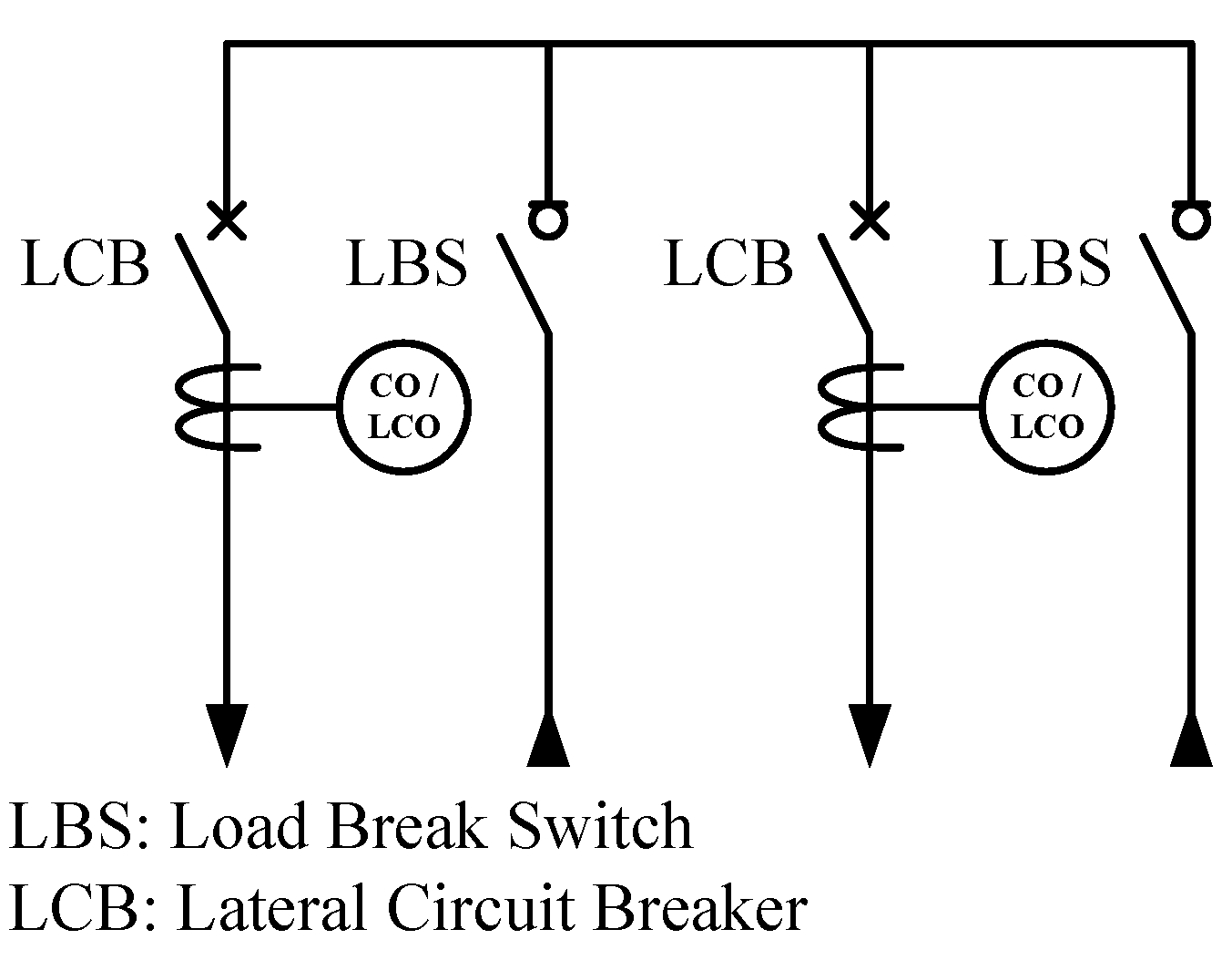
3. Underground 4-way Automatic Line Switch
The underground 4-way automatic line switches used in the DFAS employed by Taipower are depicted in
Figure 1. There are two LBS-type main feeder switches and two CB-type lateral switches in the underground 4-way automatic line switch. The voltage and current ratings of the main feeder switches are 24 kV and 600 A, respectively; the ratings of the lateral switches are 24 kV and 200 A or 600 A. For automation purpose, the CB-type lateral switches are gradually replacing the original power fuse PF-125E and function as lateral circuit breakers (LCBs). The CBs in the automatic line switch must be comprised of CO and LCO relays, and the included current transformers supervise the load current and fault current that passes through the CB. If a three-phase short circuit or single-phase ground fault takes place in the outgoing of a lateral, proper settings of the CO or LCO relay can isolate the fault via the trip action of the CB, and the protection relay of the feeder will not be activated.
Figure 1.
One-line diagram of underground 4-way automatic line switch.
Figure 1.
One-line diagram of underground 4-way automatic line switch.
Four brands (FORTUNE, TATUNG, SCHNEIDER, and GOODWELL) of underground 4-way automatic line switches are currently used in the Taipower distribution systems. The
Taipower Underground 4-Way Automatic Line Switch Material Requirement provides standard time current curve window (TCC Window) characteristics for relay operation of the automatic line switch, as shown in
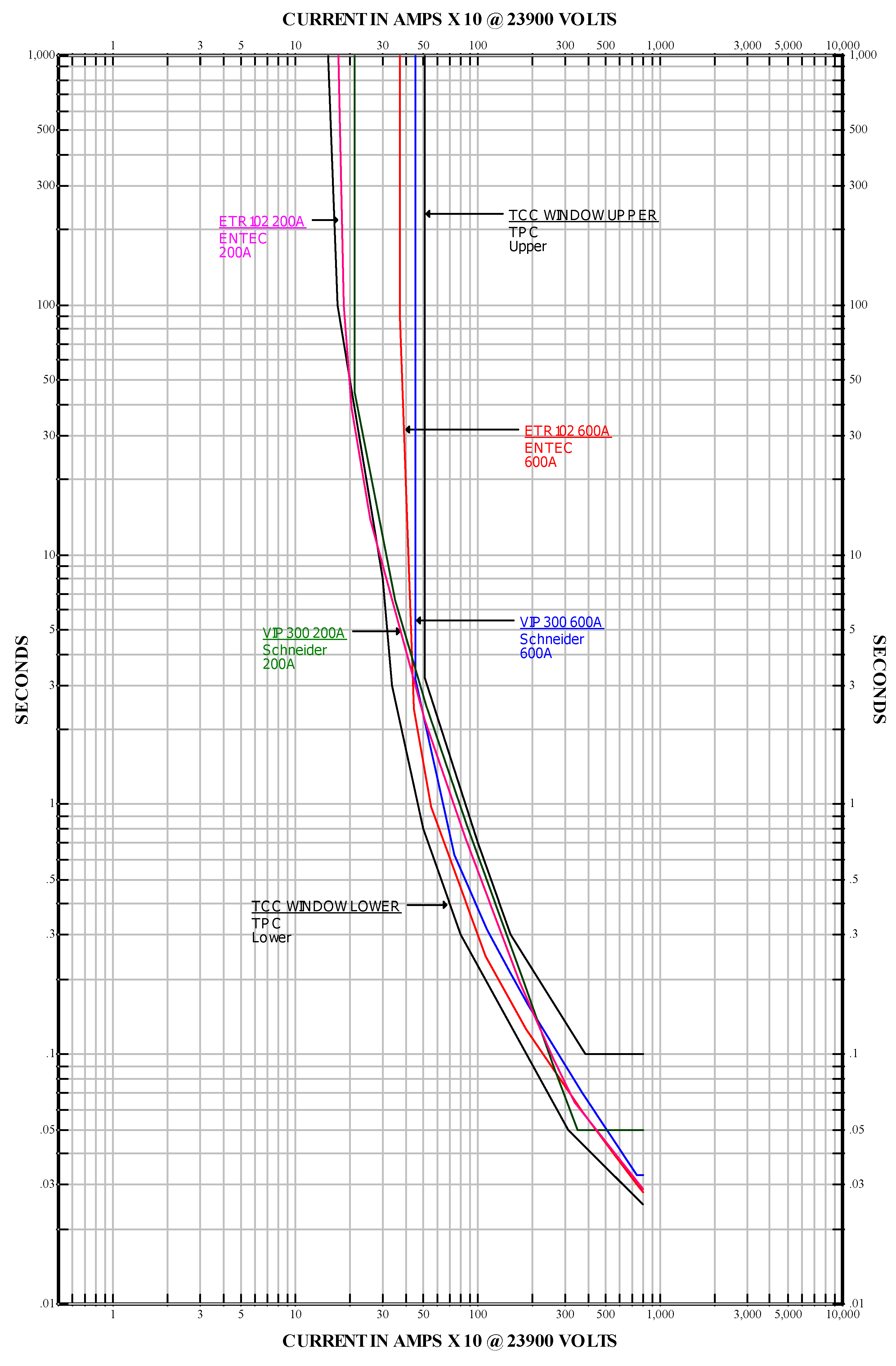
Figure 2. The terms “TCC WINDOW, UPPER” and “TCC WINDOW, LOWER” denote the upper and lower boundaries of the TCC Window.
This study seeks a substitute that has suitable curves in the TCC Window for the 4-way automatic line switch. To this end, we introduce the TATUNG ETR102 and SCHNEIDER VIP300 underground 4-way automatic line switches and compare their performance with the proposed time current curves. This study proposes four new TCCs for the CO and LCO relays of the 200 A and 600 A underground 4-way automatic line switch.
Figure 2.
ETR102, VIP300, and TCC Window time current characteristic curves.
Figure 2.
ETR102, VIP300, and TCC Window time current characteristic curves.
The typical characteristics of electromechanical CO relays for a family of similar relays from different manufacturers do not completely overlap one another. This increases the difficulty of their coordination. The ANSI and IEC committees have established unified formulae for CO relays, which relay manufacturers can now follow to facilitate better coordination results. This study uses ANSI/IEEE committee standard IEEE C37.112 for the selection of relay curves. The proposed parameters and the curve shapes of the 4-way automatic line switches are given in
Table 3 and
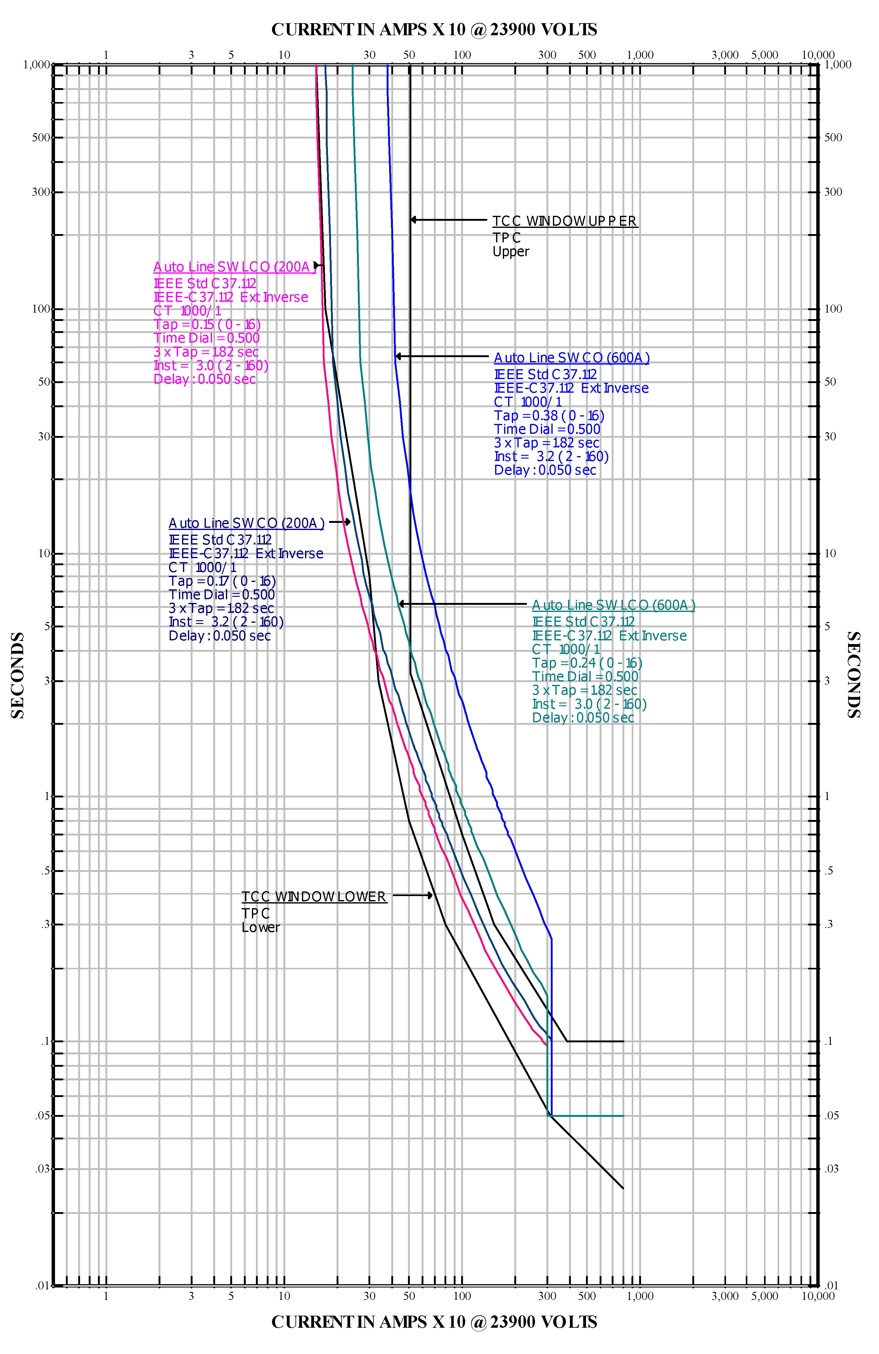
Figure 3. With regard to the aim of coordination,
Figure 3 shows that the curve “Auto Line SW CO (200 A)” is inside of the TCC Window region, while the curve “Auto Line SW CO (600 A)” is outside the TCC Window region. These curves also include “instantaneous trip” parts.
Table 3.
Proposed automatic line switch CO and LCO relays characteristic curve parameters.
Table 3.
Proposed automatic line switch CO and LCO relays characteristic curve parameters.
| Automatic line switch | Time-current curve | Pick-up current |
|---|
| CO (200A) | IEEE C37.112, E.I., CT 1000/1, T/L = 0.17/0.5, Inst. = 3.2, Delay: 0.05 s | 170 A |
| CO (600A) | IEEE C37.112, E.I., CT 1000/1, T/L = 0.38/0.5, Inst. = 3.2, Delay: 0.05 s | 380 A |
| LCO (200A) | IEEE C37.112, E.I., CT 1000/1, T/L = 0.15/0.5, Inst. = 3.0, Delay: 0.05 s | 150 A |
| LCO (600A) | IEEE C37.112, E.I., CT 1000/1, T/L = 0.24/0.5, Inst. = 3.0, Delay: 0.05 s | 240 A |
Figure 3.
Proposed automatic line switch CO and LCO relays time current characteristic curves.
Figure 3.
Proposed automatic line switch CO and LCO relays time current characteristic curves.
The feasibility of these curves has been demonstrated for the settings of the realized relays, which resolves the miscoordination problem for relay setting. In this study, the proposal of new curves for the 200 A and 600 A automatic line switches addresses their miscoordination with the PF-65E when the fault current exceeds approximately 2 kA and 3.2 kA respectively, and the others satisfy the CTI requirements. The curves of the line switches ETR102 600 A and ETR102 200A are inside the TCC Window area, but the CTI between ETR102 600A and PF-65E is not sufficient when the fault current exceeds approximately 1.2 kA. The proposed new curve “Auto Line SW CO (600 A)” increases the amount of the fault current that can be managed and reduces the region of miscoordination. The LCO relay of the automatic line switch has not yet been installed in the Taipower distribution systems. This study suggests the setting parameters and reviews the problem of coordination.
4. Linear Programming for Coordination Optimization Problem
This study adopted linear programming [
11] for CO/LCO relays coordination optimization. The nonlinear relay characteristics function as shown in APPENDIX
A.1 Overcurrent relay Equation (A.1), one variable
TDS is optimized assuming that the
Ipickup is predefined for each CO/LCO relay, and this optimization problem can be viewed as a linear programming problem. The optimization objective function can be described as follows:
where
is the number of primary relays responding for near-end fault. The variables
indicates the operating time of primary relays for near-end fault.
The coordination constraints between the primary and the backup relays are as follows:
where
and
reveal the operation time of backup relay and primary relay, respectively. CTI is the minimum coordination time interval; its value ranges from 0.2 to 0.5 s normally. In this study, the value of CTI was chosen depend upon
Feeder Protection Relay Setting Criteria.
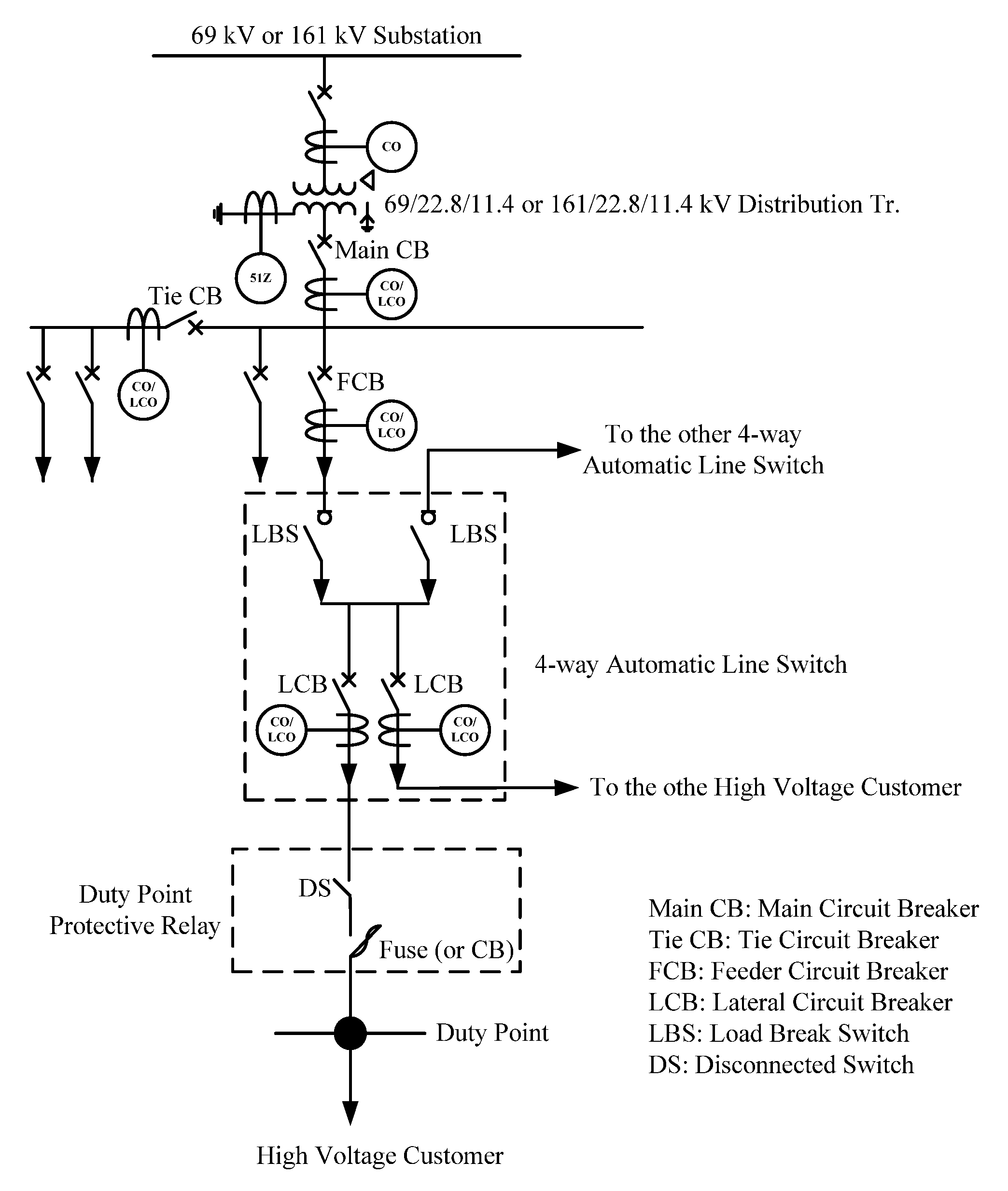
5. Current Status and Review of Distribution Feeder Protection Coordination
There are two types of substations in the Taipower power system that can be classified according to their voltage level: 161/22.8/11.4 kV corresponds to a distribution substation (D/S) and 69/22.8/11.4 kV corresponds to a secondary substation (S/S). The main difference between a D/S and an S/S is the primary voltage level of the distribution transformer.
To achieve optimal protection coordination, we will review the issue of CO and LCO relay coordination in the Taipower Minsheng D/S and Fuyuan S/S radial open-loop distribution systems, and will then offer appropriate suggestions. Our discussion includes duty point protection (switches or protective equipment) for high voltage customers, lateral protection (underground 4-way automatic line switch/LCB), feeder protection (FCB), bus-interconnection protection (Tie CB), and the secondary of distribution transformer protection (Main CB). Taipower’s radial open-loop distribution systems protection coordination scheme is shown in
Figure 4.
Figure 4.
TPC radial distribution systems protection coordination scheme.
Figure 4.
TPC radial distribution systems protection coordination scheme.
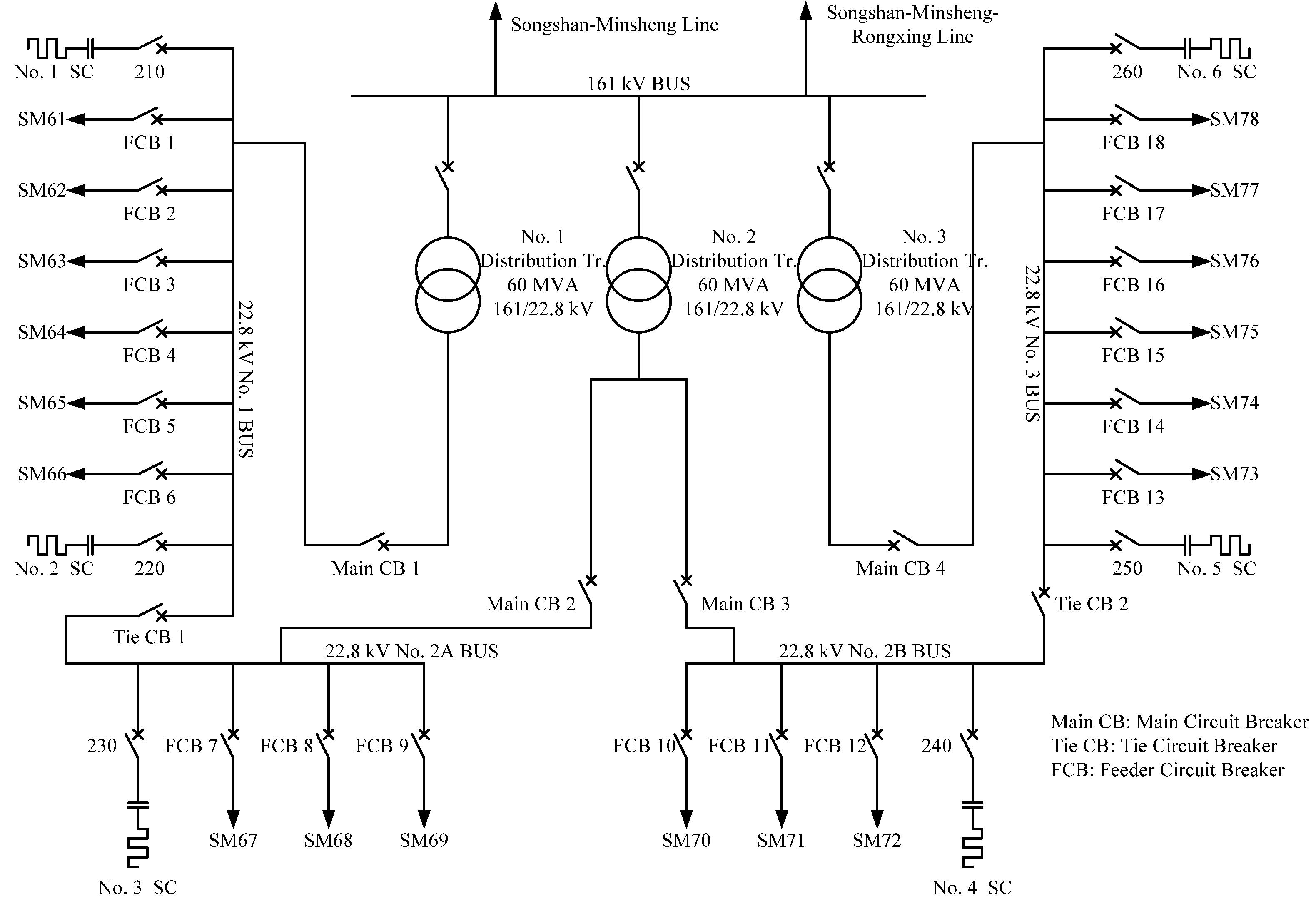
5.1. Minsheng Distribution Substation
The Minsheng D/S is composed of sub-transmission lines, three distribution transformers, six static capacitances, four Main CBs, two Tie CBs, and eighteen FCBs. It also includes 161 kV bus bar and three 22.8 kV bus bars. A one-line diagram of the Minsheng D/S is presented in
Figure 5.
Figure 5.
One-line diagram of Minsheng D/S.
Figure 5.
One-line diagram of Minsheng D/S.
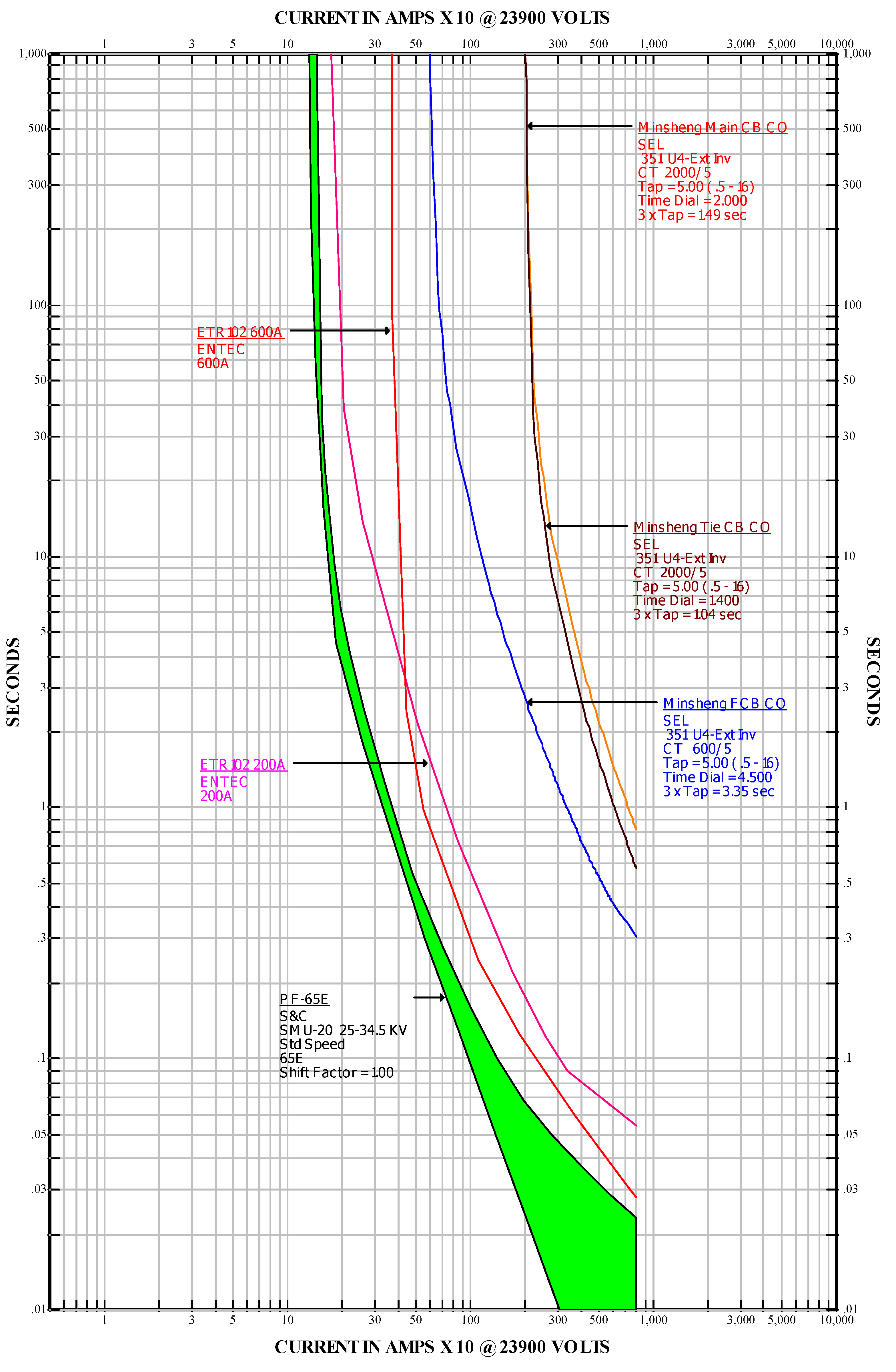
Using the coordination curve graphical capability of the commercial software package ETAP PowerPlot, the coordination problem can be completely eliminated. The original and proposed time current curves of the CO relays (Main CB, Tie CB and FCB) of the Minsheng D/S, the 4-way automatic line switches on the lateral line, and the high voltage customers’ duty point protective device PF-65E, obtained using the PowerPlot program are shown in
Figure 6 and
Figure 7, respectively. The details of the original and proposed CO relays are given in
Table 4.
Figure 6.
Original CO relays of Minsheng D/S.
Figure 6.
Original CO relays of Minsheng D/S.
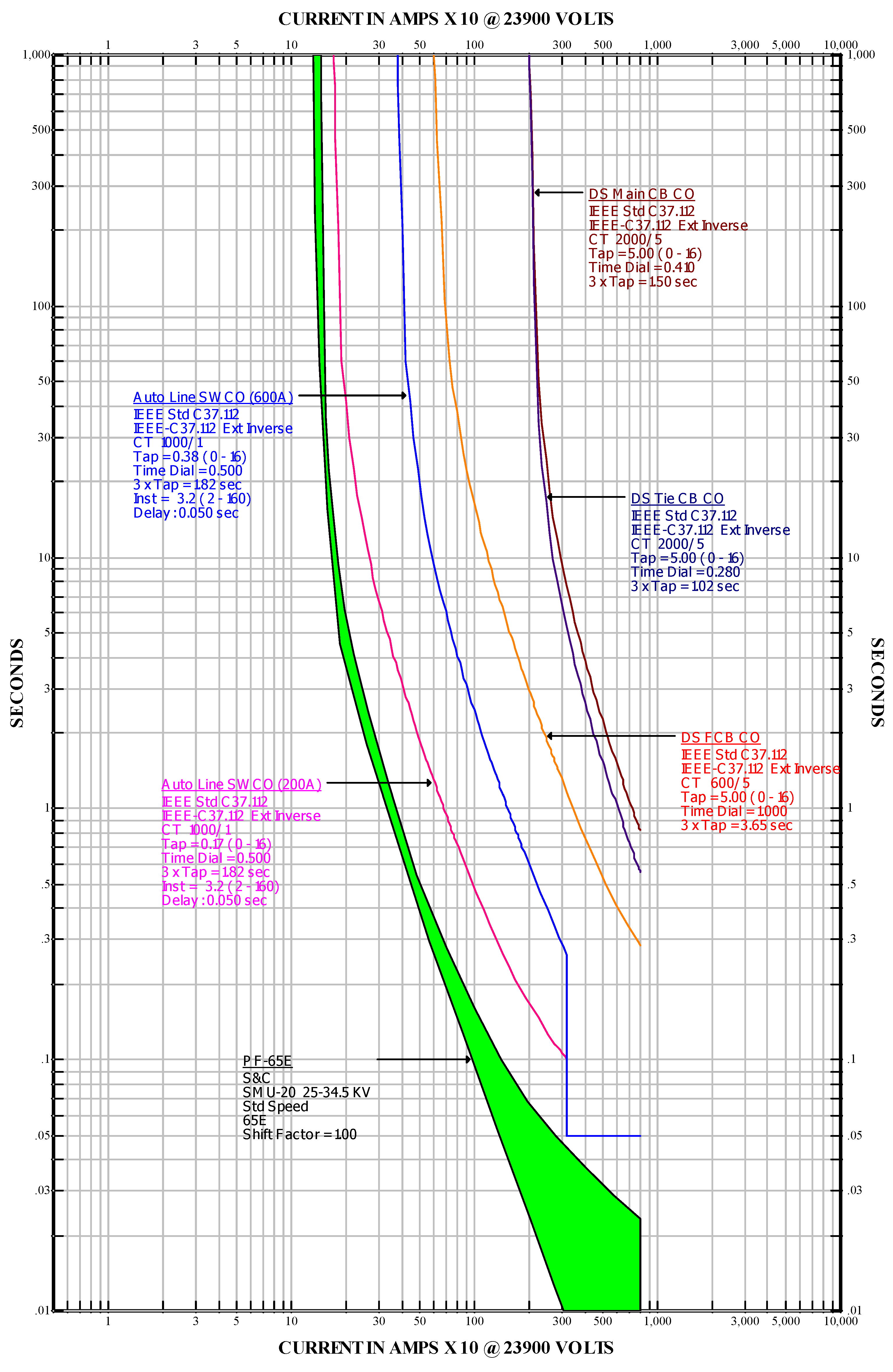
Figure 7.
Proposed CO relays of Minsheng D/S.
Figure 7.
Proposed CO relays of Minsheng D/S.
Figure 6 and
Figure 7 show that the FCB, the original automatic line switches (200 A, 600 A), and the proposed line switches are in coordination with each other for a CTI that exceeds 0.3 s, when the fault current exceeds 600 A. When the fault current exceed 2 kA, all the original and proposed automatic line switches are in miscoordination with the PF-65E for a CTI that is less than 0.1 s (except for the new 600 A automatic line switch), while the rest are in coordination at less than 2 kA.
For a fault current of 8 kA, the operation time of the relays of the Main CB, Tie CB, and FCB are given in
Table 4. In the Minsheng D/S, the operation time of the original and the proposed protective devices satisfy the setting criteria and CTI requirements. The proposed IEEE standard curves can serve as references for relay manufacturers in their selection of curve types.
Table 4.
Original and proposed CO relays of Minsheng D/S.
Table 4.
Original and proposed CO relays of Minsheng D/S.
| Range of Protection | Original Protection Type | Original Operation Time | Proposal Protection Type | Proposal Operation Time | Setting Criteria |
|---|
| High Voltage Customer’s Duty Point | PF-65E | 0.023 s | PF-65E | 0.023 s | N.A. |
| Lateral underground 4-way automatic line switch | ETR102 (600 A)
VIP300 (600 A) | 0.028 s
0.033 s | IEEE C37.112 E.I.
CT 1000/1
T/L = 0.38/0.5
Inst. = 3.2
Delay: 0.05 s | 0.05 s | N.A. |
| Distribution Transformer Secondary 23.9 kV FCB | SEL 351A U4-E.I.
CT 600/5
T/L = 5/4.5 | 0.308 s
(18.5 cycles) | IEEE C37.112 E.I.
CT 600/5
T/L = 5.0/1.0 | 0286 s
(17.2 cycles) | Below 20 cycles |
| Distribution Transformer Secondary 23.9 kV Tie CB | SEL 351A U4-E.I.
CT 2000/5
T/L = 5/1.4 | 0.578 s
(34.7 cycles) | IEEE C37.112 E.I
CT 2000/5
T/L = 5.0/0.28 | 0.56 s
(33.6 cycles) | Below 35 cycles |
| Distribution Transformer Secondary 23.9 kV Main CB | SEL 351A U4-E.I.
CT 2000/5
T/L = 5/2 | 0.827 s
(49.6 cycles) | IEEE C37.112 E.I.
CT 2000/5
T/L = 5.0/0.41 | 0.82 s
(49.2 cycles) | Below 50 cycles |
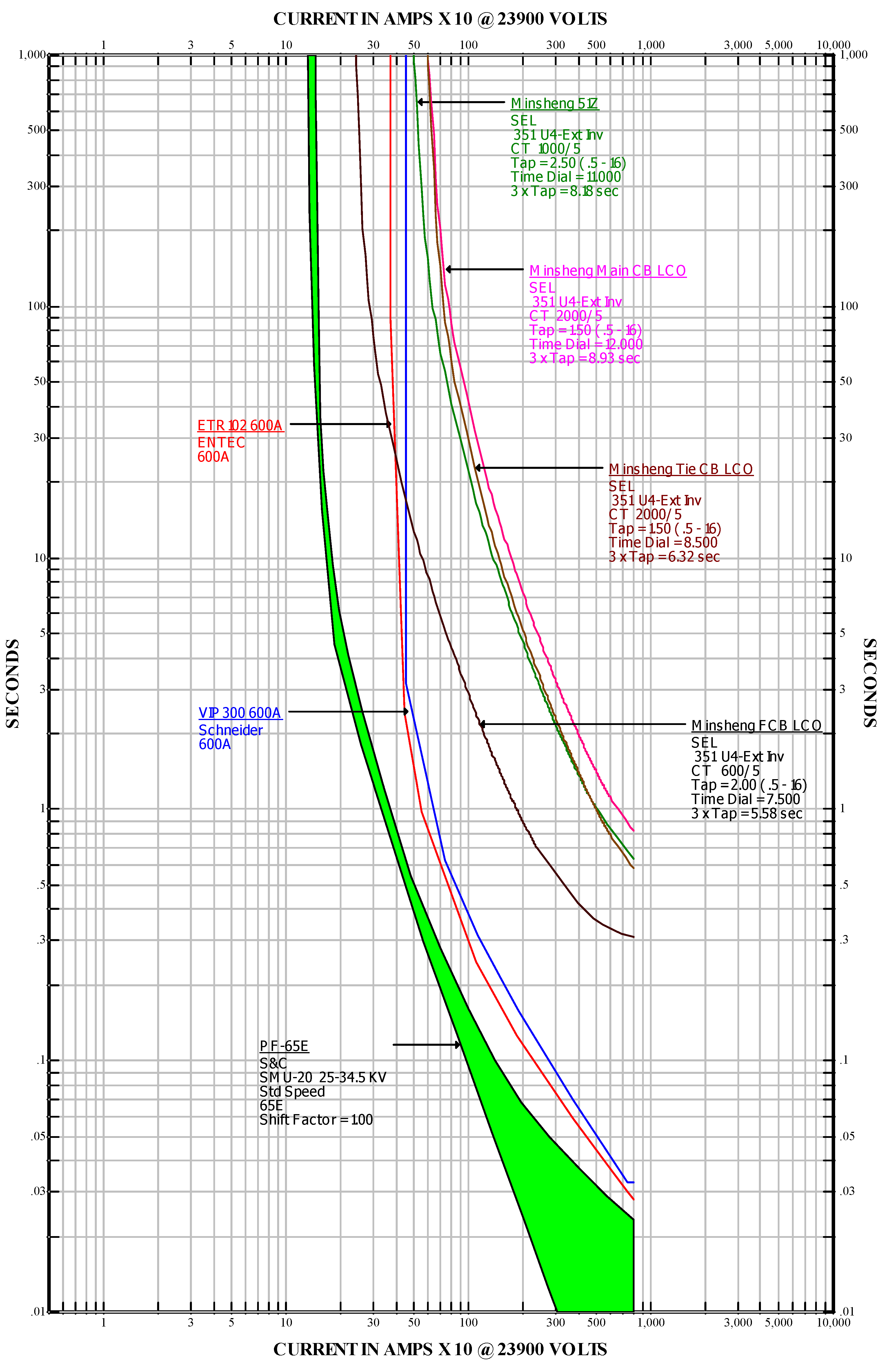
As shown in
Figure 8, the pick-up currents of the FCB LCO relay and the automatic line switches VIP300 600A, and ETR102 600A are 240 A, 375 A, and 370 A, respectively. Let us consider a line-to-ground fault that takes place in a lateral line. If we assume that value of the fault current is between 240 A and 370 A, the FCB LCO relay will become active before the automatic line switches issue a fault signal, and thus, the outage region will be enlarged. It would then be necessary to activate the automatic line switch LCO relay function.
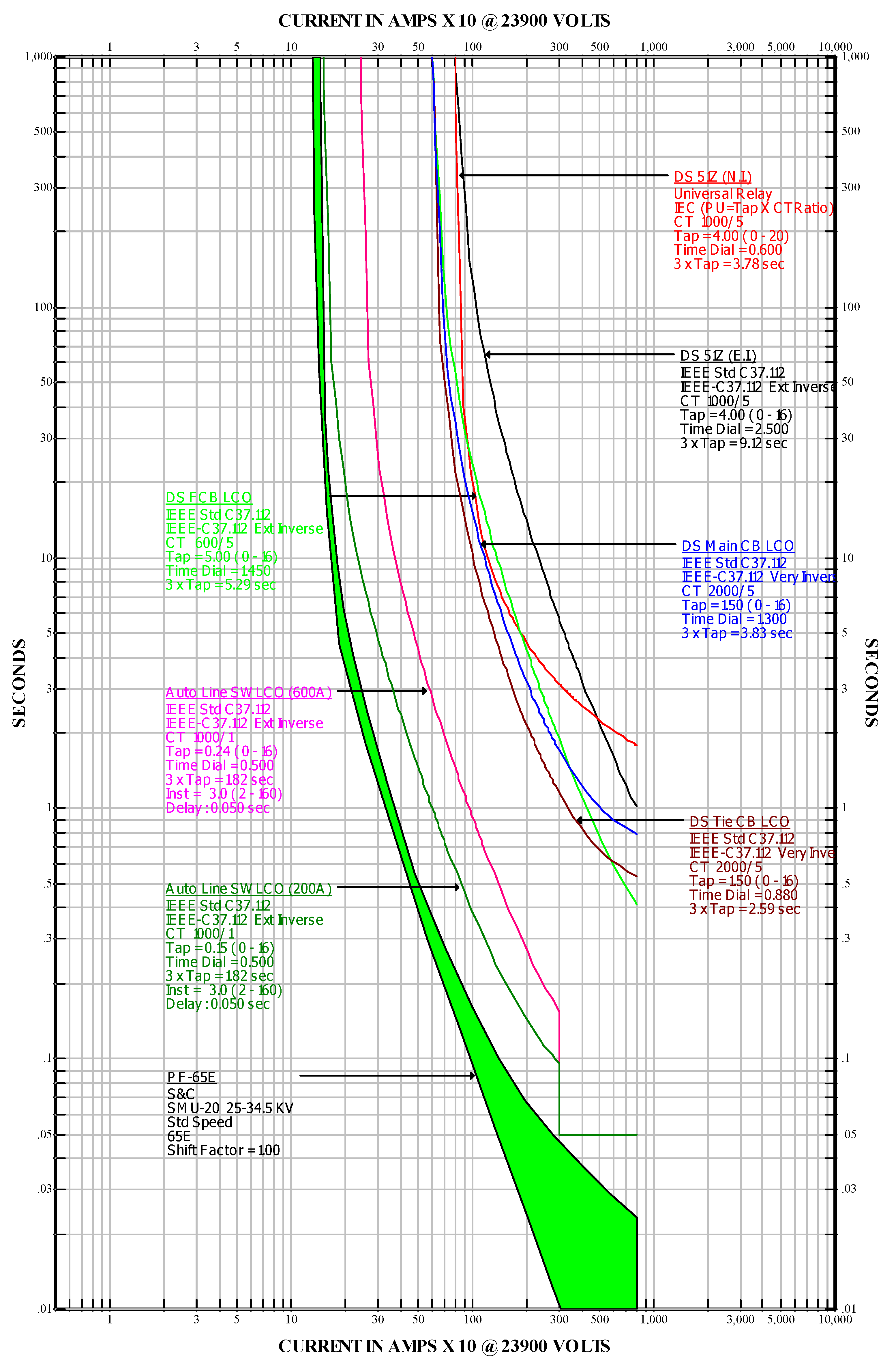
When the fault current exceeds 1.6 kA, the proposed automatic line switch LCO relay (200A) is in miscoordination with the PF-65E for a CTI that is less than 0.1 s, as shown in
Figure 9. The proposed automatic line switch LCO relay (600A) is in miscoordination with the PF-65E for fault current that exceeds 3 kA. All the proposed LCO relays for automatic line switches, FCBs, Tie CBs, Main CBs, and 51Z (E.I.) are in coordination with each other, except for 51Z (N.I.); therefore, the 51Z (N.I.) is not recommended. The details of the setting parameters of the LCO and 51Z overcurrent relays for the Minsheng D/S are listed in
Table 5.
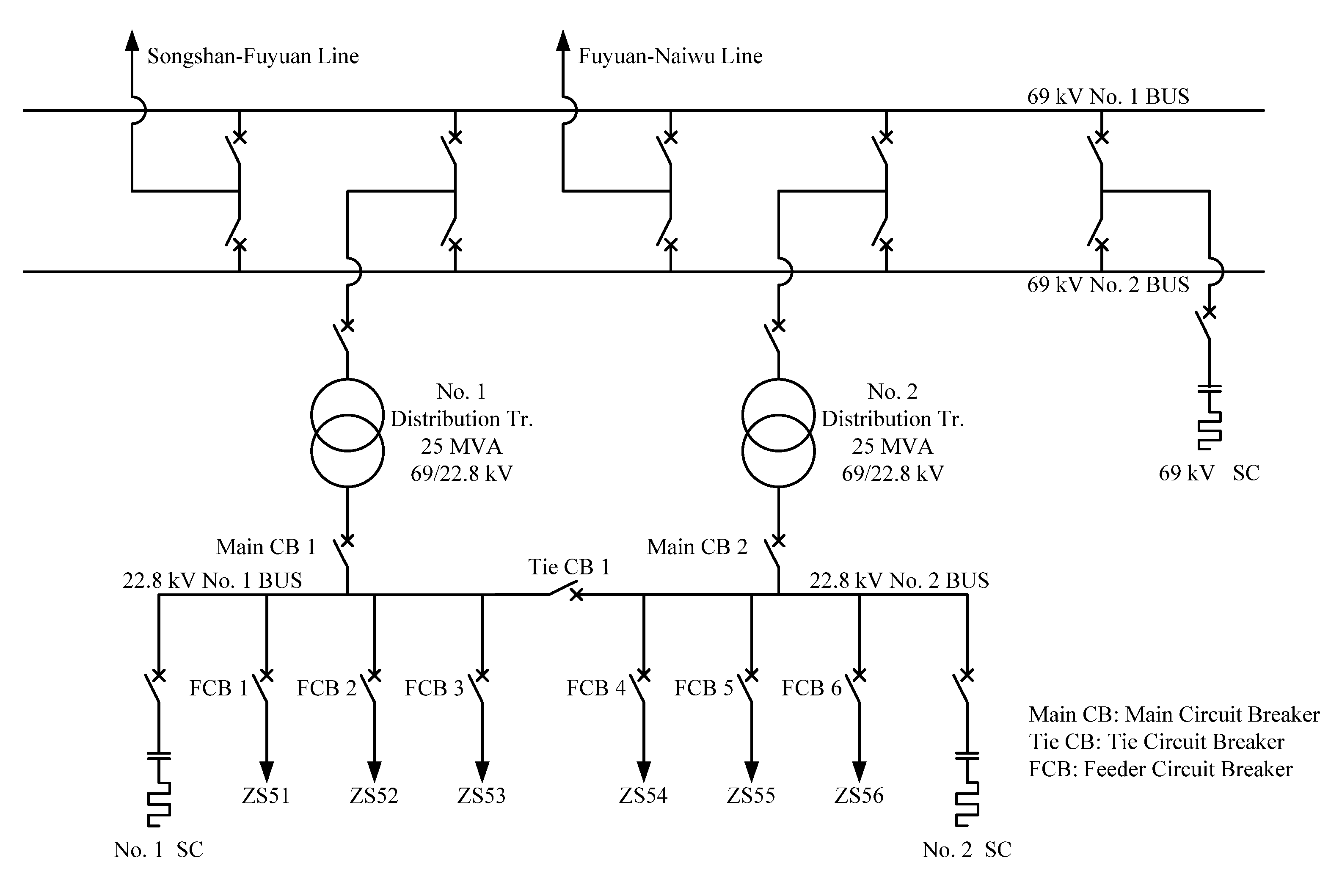
5.2. Fuyuan Secondary Substation
The Fuyuan S/S is composed of its sub-transmission lines, two distribution transformers, three static capacitances, two Main CBs, one Tie CB, and six FCBs. It also includes two 69 kV bus bars and two 22.8 kV bus bars.
Figure 8.
Original LCO relays of Minsheng D/S.
Figure 8.
Original LCO relays of Minsheng D/S.
Figure 9.
Proposed LCO relays of Minsheng D/S.
Figure 9.
Proposed LCO relays of Minsheng D/S.
Table 5.
Original and proposed LCO relays of Minsheng D/S.
Table 5.
Original and proposed LCO relays of Minsheng D/S.
| Range of Protection | Original Protection Type | Original Operation Time | Proposal Protection Type | Proposal Operation Time | Setting Criteria |
|---|
| High Voltage Customer’s Duty Point | PF-65E | 0.023 s | PF-65E | 0.023 s | N.A. |
| Lateral underground 4-way automatic line switch | ETR102 (600 A)
VIP300 (600 A) | 0.028 s
0.033 s | IEEE C37.112 E.I.
CT 1000/1
T/L = 0.24/0.5
Inst. = 3.0
Delay: 0.05 s | 0.05 s | N.A. |
| Distribution Transformer Secondary 23.9 kV FCB | SEL 351A U4-E.I.
CT 600/5
T/L = 2/7.5 | 0.311 s
(18.7 cycles) | IEEE C37.112 E.I.
CT 600/5
T/L = 2.0/1.45 | 0.279 s
(16.7 cycles) | Below 20 cycles |
| Distribution Transformer Secondary 23.9 kV Tie CB | SEL 351A U4-E.I.
CT 2000/5
T/L = 1.5/8.5 | 0.582 s
(34.9 cycles) | IEEE C37.112 V.I
CT 2000/5
T/L = 1.5/0.88 | 0.515 s
(30.9 cycles) | Below 35 cycles |
| Distribution Transformer Secondary 23.9 kV Main CB | SEL 351A U4-E.I.
CT 2000/5
T/L = 1.5/12 | 0.821 s
(49.2 cycles) | IEEE C37.112 V.I.
CT 2000/5
T/L = 1.5/1.3 | 0.791 s
(47.5 cycles) | Below 50 cycles |
| 51Z | SEL 351A U4-E.I.
CT 1000/5
T/L = 2.5/11 | 0.636 s
(38.2 cycles) | IEC N.I.
CT 1000/5
T/L = 4.0/0.6 | 1.782 s
(106.9 cycles) | Below 65 cycles |
A one-line diagram of the Fuyuan S/S is presented in
Figure 10.
Figure 10.
One-line diagram of Fuyuan S/S.
Figure 10.
One-line diagram of Fuyuan S/S.
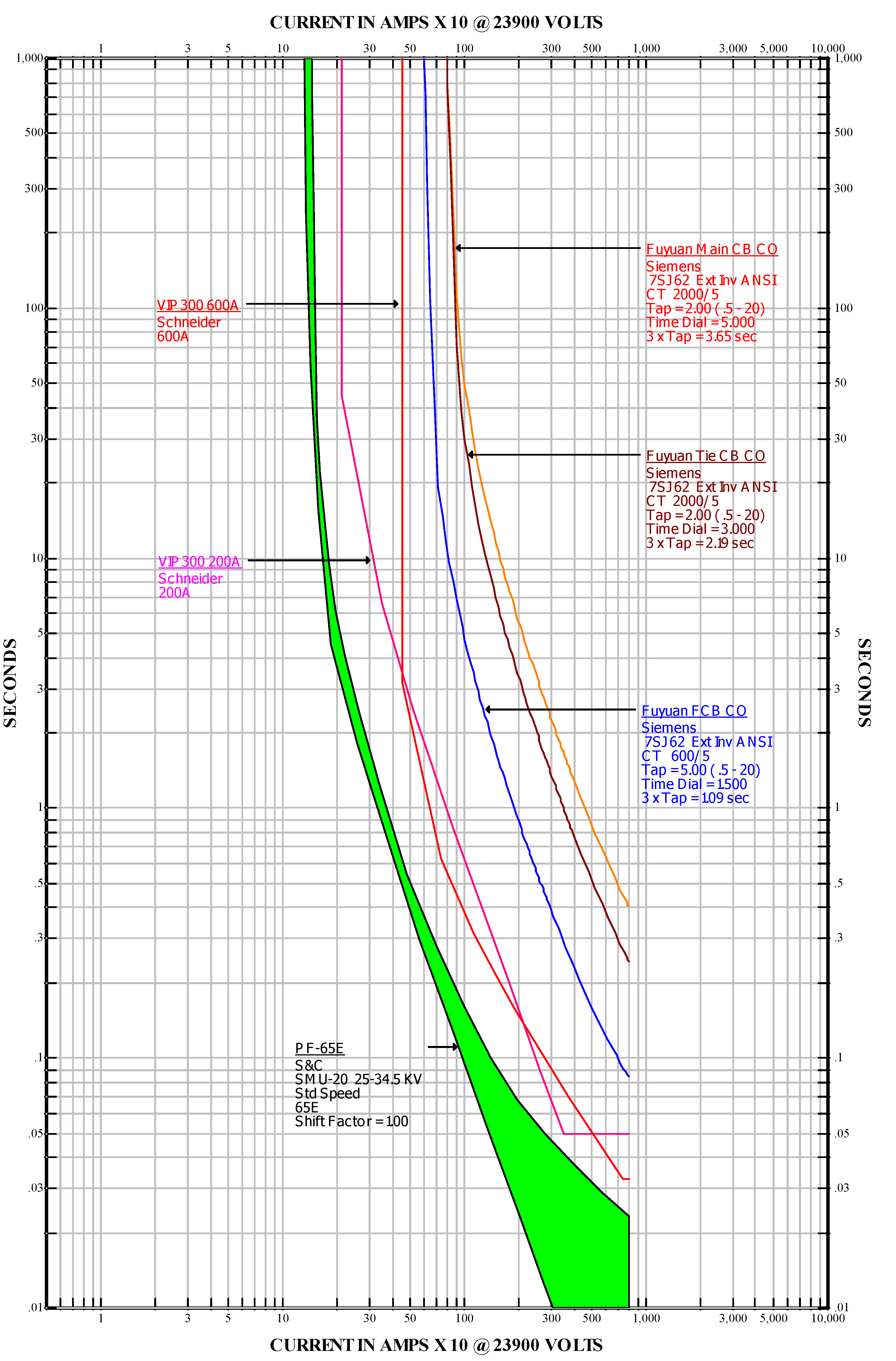
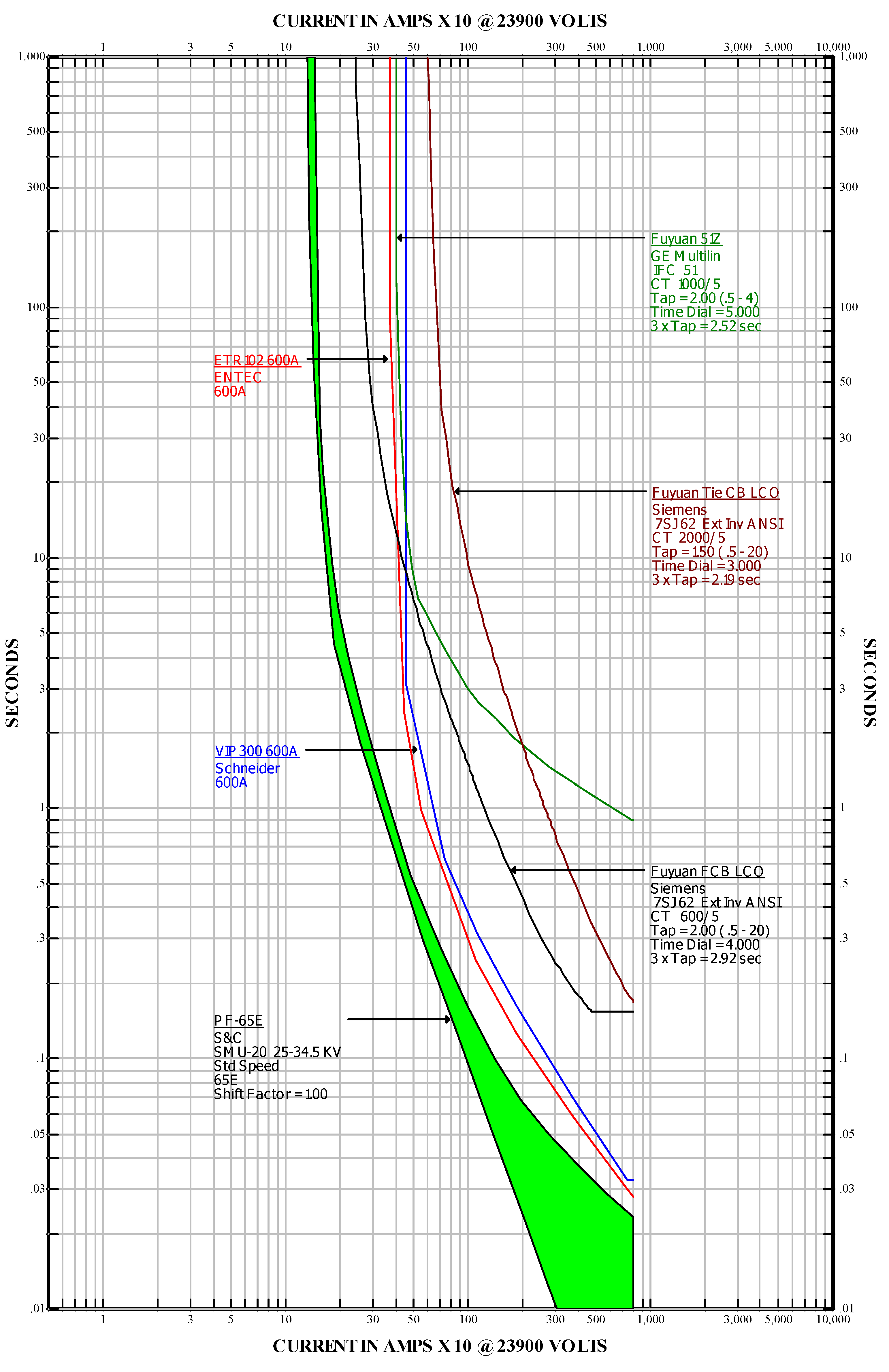
In the Fuyuan S/S, the operation time of the CO relays of the FCB is 0.085 s (5.1 cycles) when the fault current is 8 kA as shown in
Figure 11 and
Table 6. Although this operation time satisfies the regulation requirement, the CTI is not sufficient in the FCB, the automatic line switch, and the PF-65E. The proposed of IEEE C37.112 type protective devices, which conform to the regulations, are also given in
Table 6.
Figure 11.
Original CO relays of Fuyuan S/S.
Figure 11.
Original CO relays of Fuyuan S/S.
Table 6.
Original and proposed CO relays of Fuyuan S/S.
Table 6.
Original and proposed CO relays of Fuyuan S/S.
| Range of Protection | Original Protection Type | Original Operation Time | Proposal Protection Type | Proposal Operation Time | Setting Criteria |
|---|
| High Voltage Customer’s Duty Point | PF-65E | 0.023 s | PF-65E | 0.023 s | N.A. |
| Lateral underground 4-way automatic line switch | ETR102 (600 A)
VIP300 (600 A) | 0.028 s
0.033 s | IEEE C37.112 E.I.
CT 1000/1
T/L = 0.38/0.5
Inst. = 3.2
Delay:0.05 s | 0.05 s | N.A. |
| Distribution Transformer Secondary 23.9 kV FCB | Siemens 7SJ62
E.I. ANSI
CT 600/5
T/L = 5/1.5 | 0.085 s
(5.1 cycles) | IEEE C37.112 E.I.
CT 600/5
T/L = 5.0/0.8 | 0.229 s
(13.7 cycles) | Below
15 cycles |
| Distribution Transformer Secondary 23.9 kV Tie CB | Siemens 7SJ62
E.I. ANSI
CT 2000/5
T/L = 2/3.0 | 0.244 s
(14.6 cycles) | IEEE C37.112 E.I
CT 2000/5
T/L = 2.0/1 | 0.407 s
(24.4 cycles) | Below
25 cycles |
| Distribution Transformer Secondary 23.9 kV Main CB | Siemens 7SJ62
E.I. ANSI
CT 2000/5
T/L = 2/5.0 | 0.407 s
(24.4 cycles) | IEEE C37.112 E.I.
CT 2000/5
T/L = 2.0/1.4 | 0.569 s
(34.1 cycles) | Below
35 cycles |
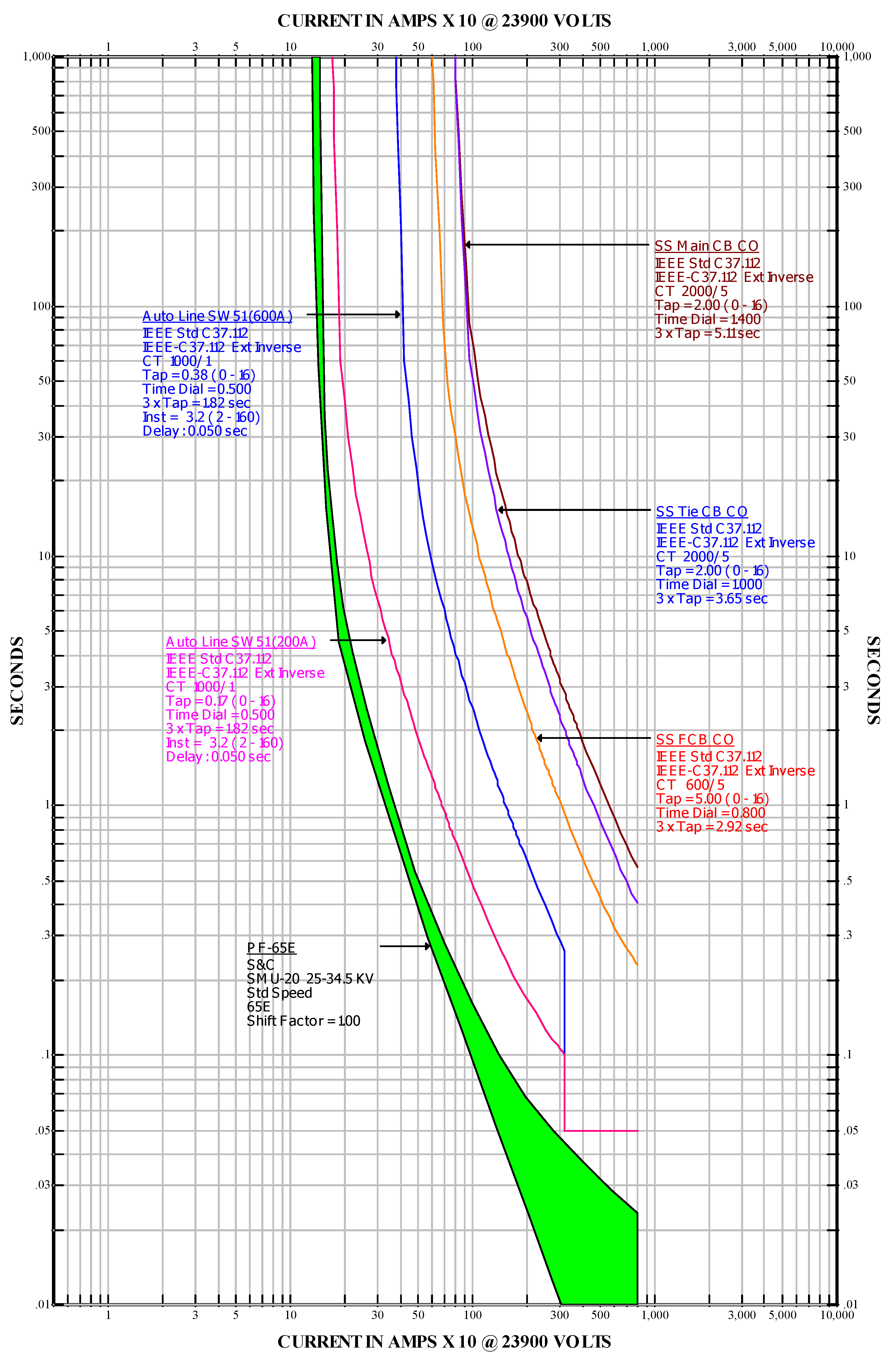
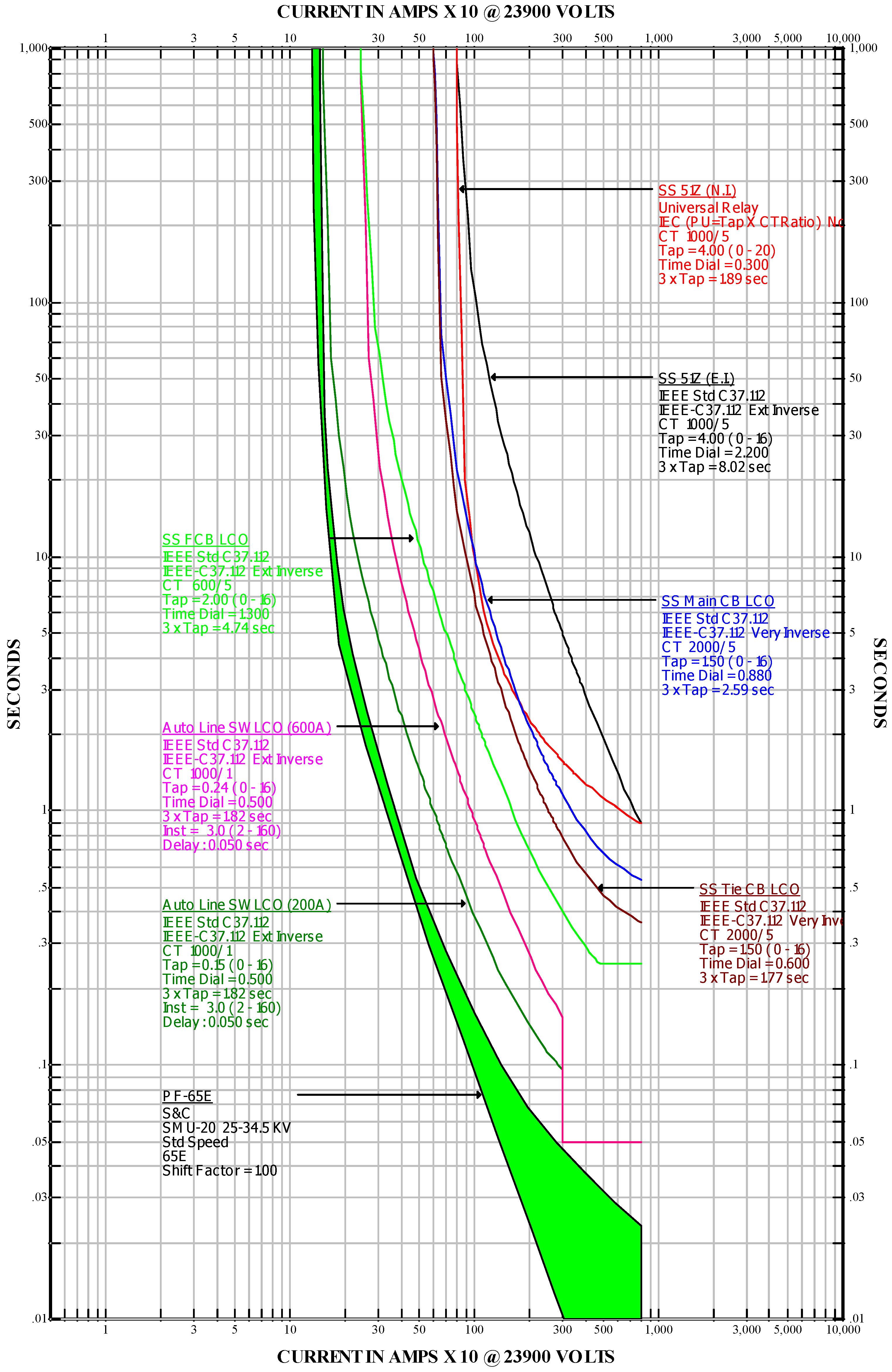
The TCCs of the proposed CO relays for an S/S are shown in
Figure 12. The proposed line switches “Auto Line SW CO (200 A)” and “Auto Line SW CO (600 A)” can be applied to the D/S or S/S distribution systems.
Let us consider a line-to-ground fault that takes place in a lateral line in the Fuyuan S/S. As shown in
Figure 13, assuming that the value of the fault current is between 240 A and 370 A, the LCO relay of the FCB will become active before the automatic line switches issue a fault signal, and thus, the outage region will be enlarged. As in the D/S condition, it would be necessary to activate the automatic line switch LCO relay function in the S/S. The “Auto Line SW LCO” is analogous to the “Auto Line SW CO” because it can be used in either the D/S or the S/S distribution systems.
All the operation time settings of the original LCO relays satisfy the requirement of Taipower, but the CTI is not sufficient. The proposed LCO relays among automatic line switches, FCB, Tie CB, Main CB, and the 51Z (E.I.) are in coordination with each other, except for the 51Z (N.I.) across the main CB; therefore, the 51Z (N.I.) is not recommended, as shown in
Figure 14. In addition, the details of the setting parameters of the LCO and 51Z relays for the Fuyuan S/S are given in
Table 7. The results of this study show that it is both feasible and practical to apply linear programming to determine the time dial setting (TDS) values of the CO and LCO relays for Main CB, Tie CB, and FCB in D/S or S/S.
Figure 12.
Proposed CO relays of Fuyuan S/S.
Figure 12.
Proposed CO relays of Fuyuan S/S.
Figure 13.
Original LCO relays of Fuyuan S/S.
Figure 13.
Original LCO relays of Fuyuan S/S.
Figure 14.
Proposed LCO relays of Fuyuan S/S.
Figure 14.
Proposed LCO relays of Fuyuan S/S.
Table 7.
Original and proposed LCO relays of Fuyuan S/S.
Table 7.
Original and proposed LCO relays of Fuyuan S/S.
| Range of Protection | Original Protection Type | Original Operation Time | Proposal Protection Type | Proposal Operation Time | Setting Criteria |
|---|
| High Voltage Customer’s Duty Point | PF-65E | 0.023 s | PF-65E | 0.023 s | N.A. |
| Lateral underground 4-way automatic line switch | ETR102 (600 A)
VIP300 (600 A) | 0.028 s
0.033 s | IEEE C37.112 E.I.
CT 1000/1
T/L = 0.24/0.5
Inst. = 3.0
Delay: 0.05 s | 0.05 s | N.A. |
| Distribution Transformer Secondary 23.9 kV FCB | Siemens 7SJ62 E.I. ANSI
CT 600/5 T/L=2.0/4.0 | 0.154 s
(9.24 cycles) | IEEE C37.112 E.I.
CT 600/5
T/L = 2.0/1.3 | 0.25 s(15 cycles) | Below
15 cycles |
| Distribution Transformer Secondary 23.9 kV Tie CB | Siemens 7SJ62 E.I. ANSI
CT 2000/5 T/L=1.5/3.0 | 0.169 s
(10.1 cycles) | IEEE C37.112 V.I.
CT 2000/5
T/L = 1.5/0.6 | 0.365 s
(21.9 cycles) | Below
25 cycles |
| Distribution Transformer Secondary 23.9 kV Main CB | N.A. | N.A. | IEEE C37.112 V.I.
CT 2000/5
T/L = 1.5/0.88 | 0.535 s(
32.1 cycles) | Below
35 cycles |
| 51Z | GE Multilin IFC51
CT 1000/5 T/L = 2.0/5.0 | 0.244 s
(14.6 cycles) | IEC N.I.
CT 1000/5
T/L = 4.0/0.3 | 0.891 s
(53.5 cycles) | Below
55 cycles |
IEEE C37.112 E.I.
CT 1000/5
T/L = 4.0/2.2 | 0.894 s
(53.6 cycles) |
6. Conclusions
Distribution feeder automation system (DFAS) can improve the operation of distribution system. Power interruption and restoration can be performed remotely without field crew. DFAS can perform rapid fault detection, fault isolation, power restoration in upstream region, and provide alternative power supply suggestion when a fault occurs. The advantages of DFAS include:
Less dispatch and traffic, and more safety for the crew personnel.
Faster fault identification and isolation, shorter outage time, and smaller region of outage.
Longer service time periods of distribution feed lines and equipments.
This study discusses and analyzes the operations of the CO and LCO relays of the lateral circuit breakers (LCB) in an underground 4-way automatic line switch. When a fault occurs in the lateral, the relays should trip CBs, isolate the fault, and keep other customers on the same feeder from outage. To accomplish such goals and to benefit the most from system automation, all the protection equipments in the distribution circuit must be properly coordinated.
Based on Taipower regulations, this study discusses and formulates the problem of coordination of the power fuse PF-65E, automatic line switch, FCB, Tie CB, and Main CB. The simulation results reported in this paper demonstrate that these new relay setting parameters can be implemented practically and can provide adequate resolution of the coordination problems of a D/S or an S/S in the distribution systems.

