1. Introduction
The over-voltage has a great impact on the safety and stability of the power system. Currently, with continuous improvement of the voltage levels of the grid, over-voltage represents a stronger hazard for the system. Therefore, the study of feature extraction and over-voltage identification algorithms has a very important significance for the safe operation of the grid. Meanwhile, real-time monitoring, online identification and smart restrictions of over-voltage are an important part in the constriction of self-healing smart grids.
In isolated neutral networks, the ferroresonance caused by the magnetizing inductance saturation of the electromagnetic potential transformer (PT) [
1,
2] and the power frequency over-voltage caused by faults like single phase-to-ground or wire breakage may exist for a long time, with which the security of the system may be severely threatened. A lot of research has been done on the identification and classification of the ferroresonance [
3,
4], ground faults [
5] and other kinds of over-voltages [
6], but there are still a lot of research challenges that need to be resolved. In some cases, if the grounding resistance is comparatively high, the voltage features of single phase-to-ground may appear extremely similar to the fundamental ferroresonance. It is very difficult to distinguish such kinds of over-voltages. If an improper suppression operation is applied to the networks due to incorrect identification of over-voltage, the accident is likely to further worsen.
Through a theoretical research, this paper analyzes five kinds of power frequency over-voltage. By comparing the differences between three-phase voltages, currents and neutral point voltage, an identification and classification scheme based on various characteristic quantities has been worked out.
It should be noted that the classification of fundamental ferroresonance and single phase-to-ground fault is one of the most difficult parts in the over-voltage identification research. Two kinds of over-voltages show high similarity in steady-state voltage and current under some conditions, and because ferroresonance may be triggered by a short ground fault, the transient component is not a good candidate for the identification feature. In this paper, an effective method based on zero sequence current features is presented to distinguish the two kinds of over-voltages. This method has high accuracy and adaptability, which will not be influenced by either grounding resistance value or the degree of magnetizing inductance saturation.
2. Fundamental Ferroresonance
In a power system, the potential transformer is usually installed on the feeder or bus with its neutral point directly grounding. In the case of some disturbances in the system, such as switching circuit breakers [
7] and grounding fault missing [
8], PT’s magnetizing inductance may form a nonlinear ferroresonance circuit with the system-to-ground capacitance.
Ferroresonance is a nonlinear resonance phenomenon that can affect power networks. The main problem with ferroresonance is that an over-voltage or an over-current is generated. Ferroresonance can occur if a nonlinear saturable iron core inductor is substituted into the LC circuit. In this case, the current will contain harmonics and phasor analysis can no longer be used to solve the circuit. However, in practical, when the fundamental ferroresonance occurs, the harmonic component in the over-voltage and over-current is very small compared to the fundamental component [
7,
9,
10].
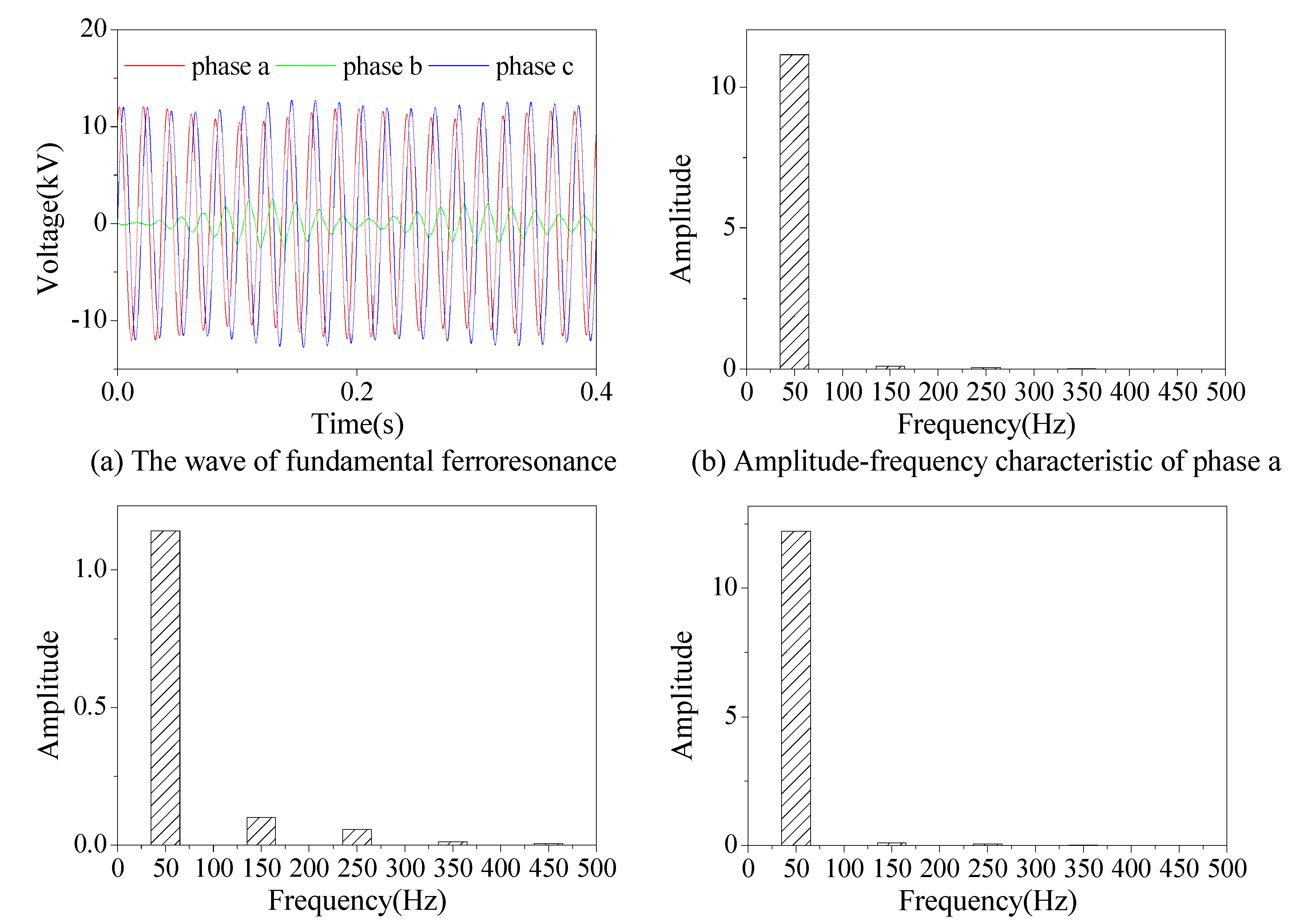
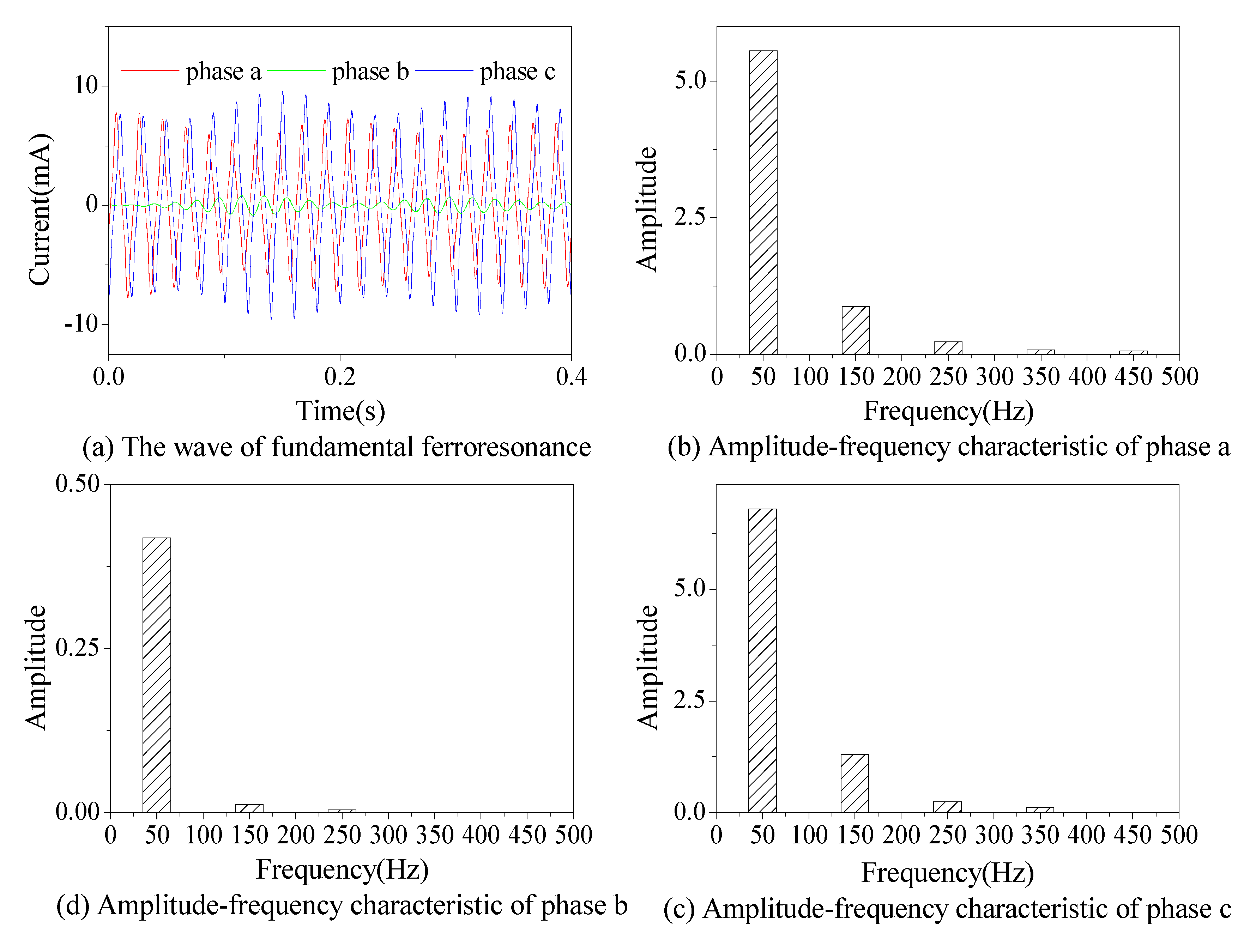
Figure 1 and
Figure 2 show the typical fundamental ferroresonance over-voltage and over-current signals in three phases and the fast Fourier transform result of each signal. From these two figures, it can be found that the fundamental component is the dominant part of the over-voltage and over-current signals. The harmonic component is small compared to the fundamental component. Moreover, the main purpose of this paper is to classify the fundamental ferroresonance over-voltage among other kinds of power frequency over-voltages. It is very important to find the fundamental component characteristics of these three kinds of over-voltages, which are their main characteristics. The harmonic component is very small compared to the fundamental component, which shows that the harmonic component is not the main characteristic of the fundamental ferroresonance. In the signal classification and pattern recognition area, it is helpful to find the main characteristics of signals. Therefore, in order to simplify the analysis and highlight the characteristics of the fundamental component, the harmonic component of the over-voltage and over-current is ignored in our analysis on the fundamental ferroresonance. Thus the fundamental component can be used for the analysis of the drift of the neutral point of the fundamental ferroresonance under different conditions. References [
11,
12] have studied the fundamental ferroresonance in single-phase circuit using phasor representation, which can provide a simple explanation of the relationship between the voltage and current in the fundamental ferroresonance. Thus the phasor representation can be adopted in this paper to analyze the drift of the neutral point of the fundamental ferroresonance under different conditions.
Figure 1.
Simulated fundamental ferroresonance over-voltage signals and the Fourier transform result.
Figure 1.
Simulated fundamental ferroresonance over-voltage signals and the Fourier transform result.
Figure 2.
Simulated fundamental ferroresonance over-current signals and the Fourier transform result.
Figure 2.
Simulated fundamental ferroresonance over-current signals and the Fourier transform result.
2.1. Voltage Features of Fundamental Ferroresonance
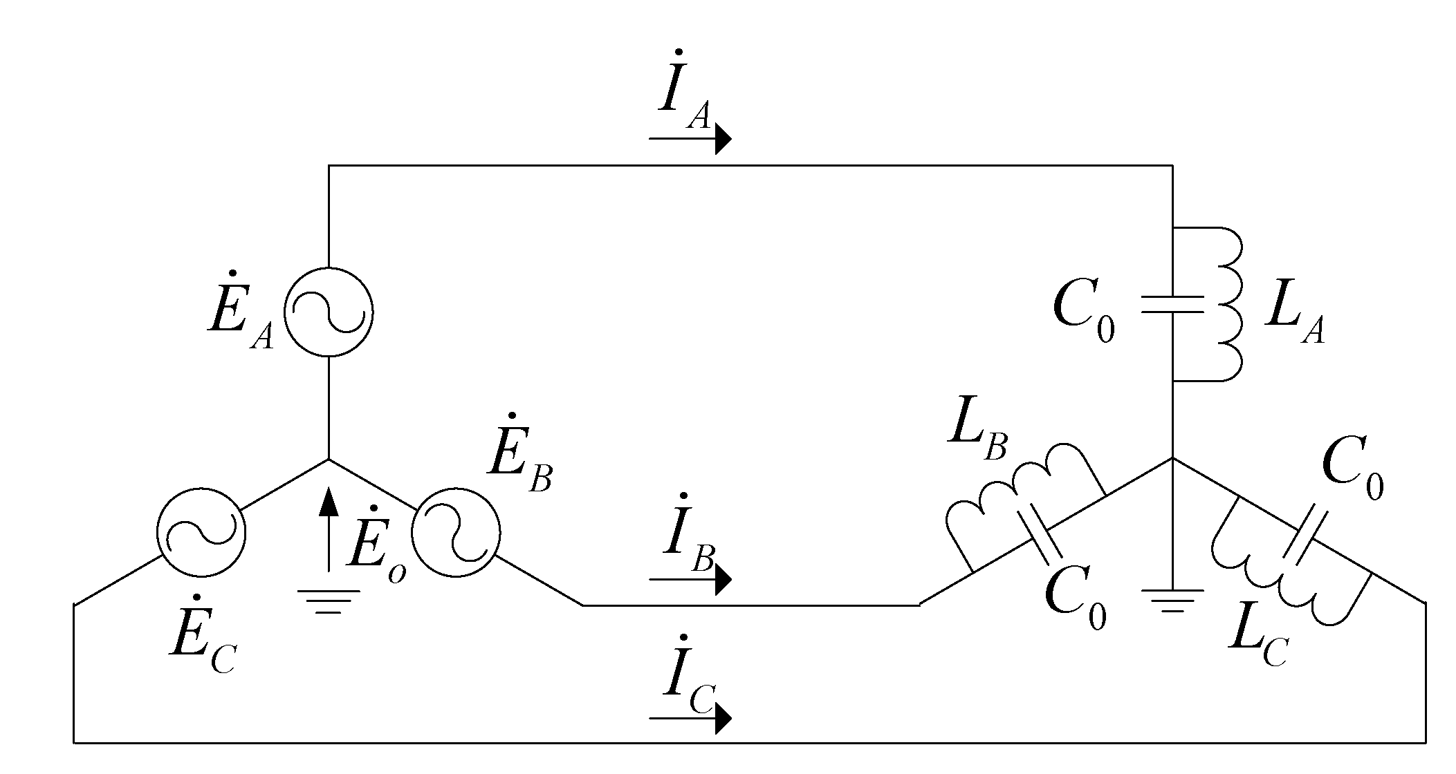
Figure 3 shows the equivalent circuit of neutral grounded PT parallel connected with system-to-ground capacitances.
,
,
are the supply voltages,
is the neutral point voltage.
LA,
LB,
LC are the PT’s nonlinear inductances, where
, is a symbol of dynamic inductance.
C0 is the system-to-ground capacitance.
Figure 3.
Equivalent circuit of a PT’s ferroresonance.
Figure 3.
Equivalent circuit of a PT’s ferroresonance.
The admittances of each phase are
YA,
YB,
YC, follow Kirchhoff’s first law:
When the system works in the normal situation, the cores of PT’s nonlinear inductance are running in their linear part. Generally, the value of PT’s working inductance is a large number, and XL > XL0, which means the parallel circuit of each phase is capacitive and YA = YB = YC, therefore = 0. If a ferroresonance occurs on the PT, one or more magnetizing inductance will become saturated, which leads to a decrease of the inductance value. Once XL < XC0, the parallel circuit will become inductive. Depending on the degrees of nonlinear inductance’s saturation, it can be described by three situations.
Figure 4.
(a) Vector graph of ferroresonance due to non-serious saturation; (b) Vector graph of ferroresonance due to one-phase serious saturation; (c) Vector graph of ferroresonance due to two-phase serious saturation.
Figure 4.
(a) Vector graph of ferroresonance due to non-serious saturation; (b) Vector graph of ferroresonance due to one-phase serious saturation; (c) Vector graph of ferroresonance due to two-phase serious saturation.
1. PT’s 3 nonlinear inductances are saturated in different degrees, but parallel circuits in three phases are all still capacitive, therefore the phase of the currents
,
,
lead the phase for the voltage by 90 degrees. According to vector analysis, the neutral point O’ must be at the internal of the voltage vector triangle, shown as
Figure 4a, otherwise it can not meet the current balance condition:
.
2. One phase is inductive because of serious saturation, and the other 2 phases are still capacitive. Assume phase-A is the serious saturation one, therefore
is falls behind the voltage. In order to meet the current balance condition, the neutral point O moves to the outside of the voltage triangle, shown as point O’ in
Figure 4b.
3. Two phases becomes inductive because of serious saturation, the other phase is still capacitive. The neutral point O’ is outside of the voltage triangle too, shown as point O’ in
Figure 4c.
In summary, when a fundamental ferroresonance occurs, the neutral point voltage could be at any place, inside or outside of the voltage vector triangle.
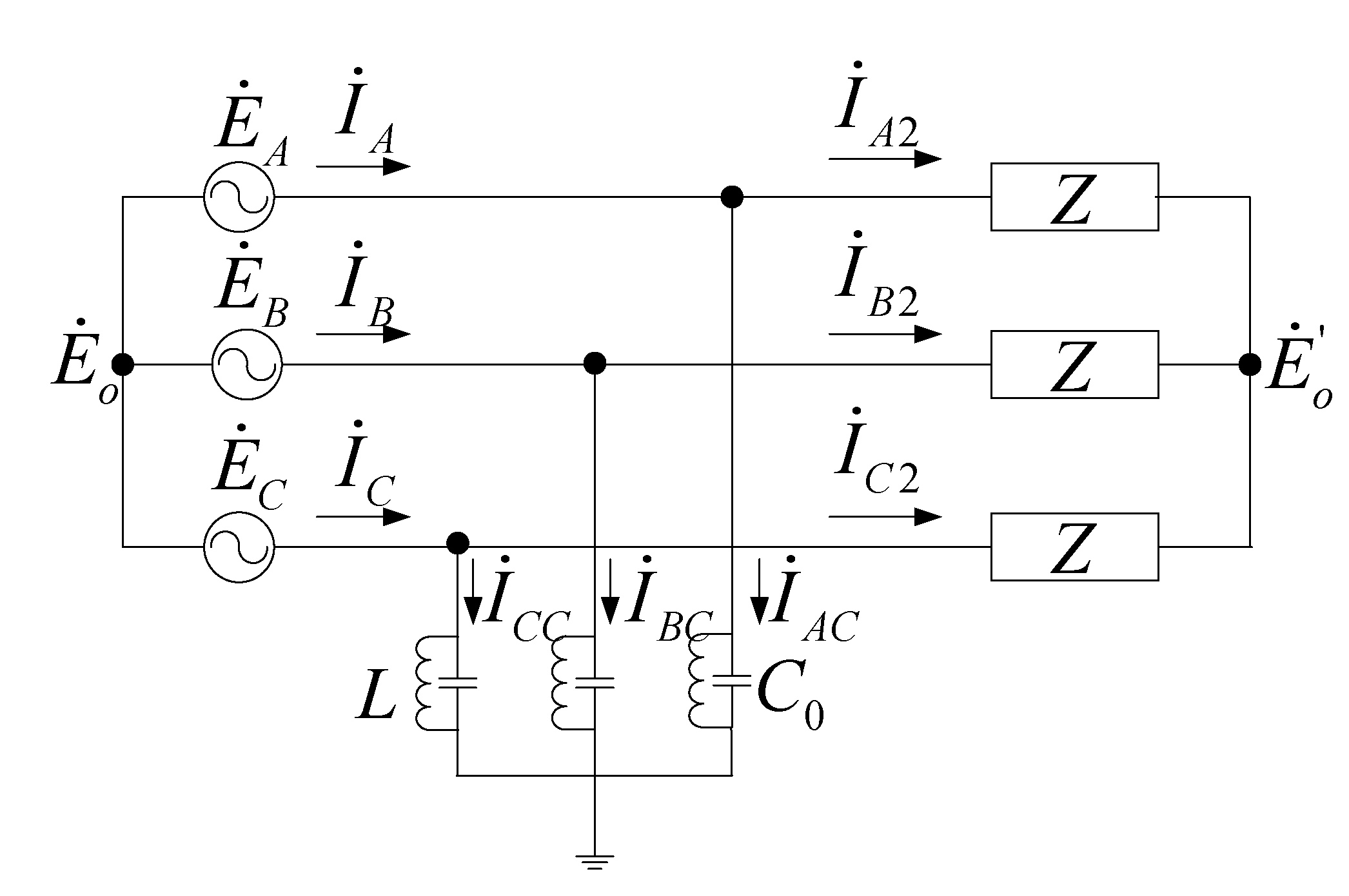
2.2. Current Features of Fundamental Ferroresonance
When ferroresonance occurs in isolated neutral networks, the currents in three phases are composed by the currents through PT’s nonlinear inductance, system-to-ground capacitances and loads.
Figure 5.
The equivalent circuit of PT’s ferroresonance, considering the loads.
Figure 5.
The equivalent circuit of PT’s ferroresonance, considering the loads.
In
Figure 5,
is the neutral point voltage at the supply side,
is the neutral point voltage at the load side,
L is PT’s nonlinear inductance,
C0 is system-to-ground capacitance,
Z is equivalent load. This circuit is solved through branch current method as follows:
Therefore the currents through the loads are:
This means the currents flowing through the loads are independent of the neutral point voltage. In practice, current in each phase is composed of load current and the system-to-ground capacitive current. According to Shott and Peterson’s research [
13], the ferroresonance changes from subharmonic to fundamental and harmonic ferroresonance as the ratio of
XC0/
Xm changes, where
XC0 is the zero sequence capacitive reactance and
Xm is the PT’s working inductive reactance. For the fundamental frequency ferroresonance, the value of
XC0/
Xm is between 0.07 and 0.55, based on a typical transformer saturation curve. The range of
XC0/
Xm will not change too much for different saturation curves. Because the inductor value of PT’s magnetizing inductance is large, therefore, the corresponding system-to-ground capacitance has a very small value, and so does the current through the system-to-ground capacitance. In summary, when fundamental ferroresonance occurs, there are no significant changes in three-phase currents that can be observed.
3. Single Phase-to-Ground
The single phase-to-ground fault ignoring the grounding resistance at the fault point is also known as a metallic ground fault. When a metallic ground fault occurs, the voltage amplitude will drop to zero in the fault phase. However, the operating experience shows that the type of the ground faults in the distribution networks is usually non-metallic ground, such as the crawl flash due to coronas caused by surface cracks and breakdown of insulators, contacts between overhead lines and tree branches, and grounding faults occurring in areas of high soil resistivity.
Figure 6.
Equivalent circuit of single phase-to-ground.
Figure 6.
Equivalent circuit of single phase-to-ground.
Figure 6 shows the equivalent circuit of single phase-to-ground. Phase-A is grounded through resistor
R. PT’s magnetizing inductance is unsaturated in this case, so that it is ignored. According to Kirchhoff’s first law:
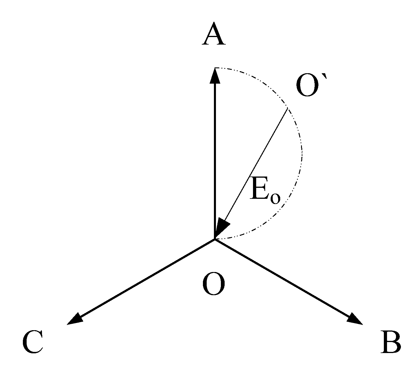
The neutral point voltage can be described as:
The possible position of neutral point O’ can be drawn as a semicircle in the vector graph, shown as
Figure 7.
Figure 7.
Vector graph of single phase-to-ground.
Figure 7.
Vector graph of single phase-to-ground.
If a power frequency over-voltage occurs in the power system, and its neutral point O’ is on the semicircle. It is hard to distinguish whether the type of over-voltage is ferroresonance or single phase-to-ground based on the voltage waveform features.
The simulation software ATP/EMTP is employed to verify the highly similarity of these two kinds of power frequency over-voltage. The system voltage is 10 kV, the system structure of the simulation model is shown in
Figure 5 and
Figure 6. In the simulation model, the value of load
Z is 245 +
j9.1875 Ω, the value of system-to-ground capacitance
C0 is 0.00209 μF. The single phase-to-ground over-voltage takes place in 0.025 s, and the ground resistance is 2.5 kΩ. In practice, ferroresonance is triggered by switching circuit breakers or disconnectors, clearing faults, the circuit breaker malfunction, or when a system loses its grounding,
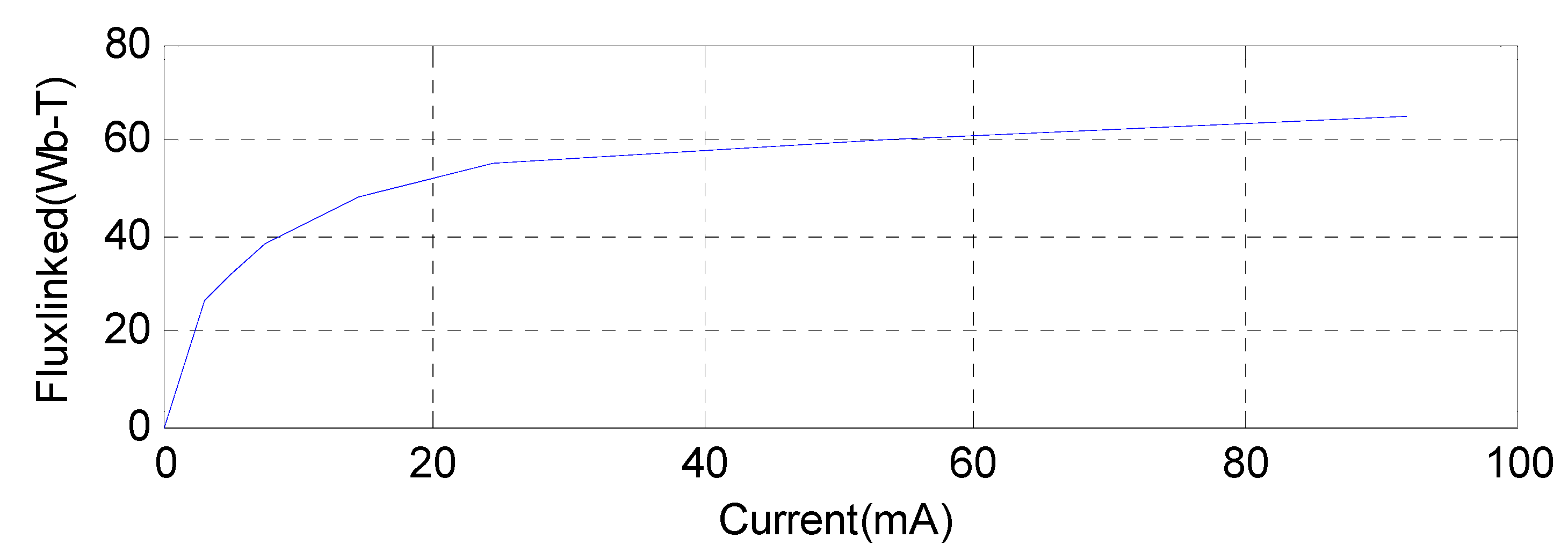
etc. A ferroresonance circuit which can be reduced to a series resistance, nonlinear inductance, and capacitance one is sometimes formed. The inductance may be forced to operate in the saturated region of its excitation characteristic, resulting in a sharp change in the voltage across the inductance and the current through it. Consequently, excessive current and voltage may result in a disaster, including the flashover of external insulation, burning out of PTs, or the destruction of metal-oxided resistors. In this paper, the ferroresonance over-voltage triggered by a single phase-to-ground from 0.025 s to 0.045 s. The excitation curve of PT’s nonlinear inductance used in simulation model is shown as
Figure 8. The excitation curve is calculated from the discrete current-voltage characteristic, which is measured experimentally.
Figure 8.
Excitation curve of PT’s nonlinear inductance.
Figure 8.
Excitation curve of PT’s nonlinear inductance.
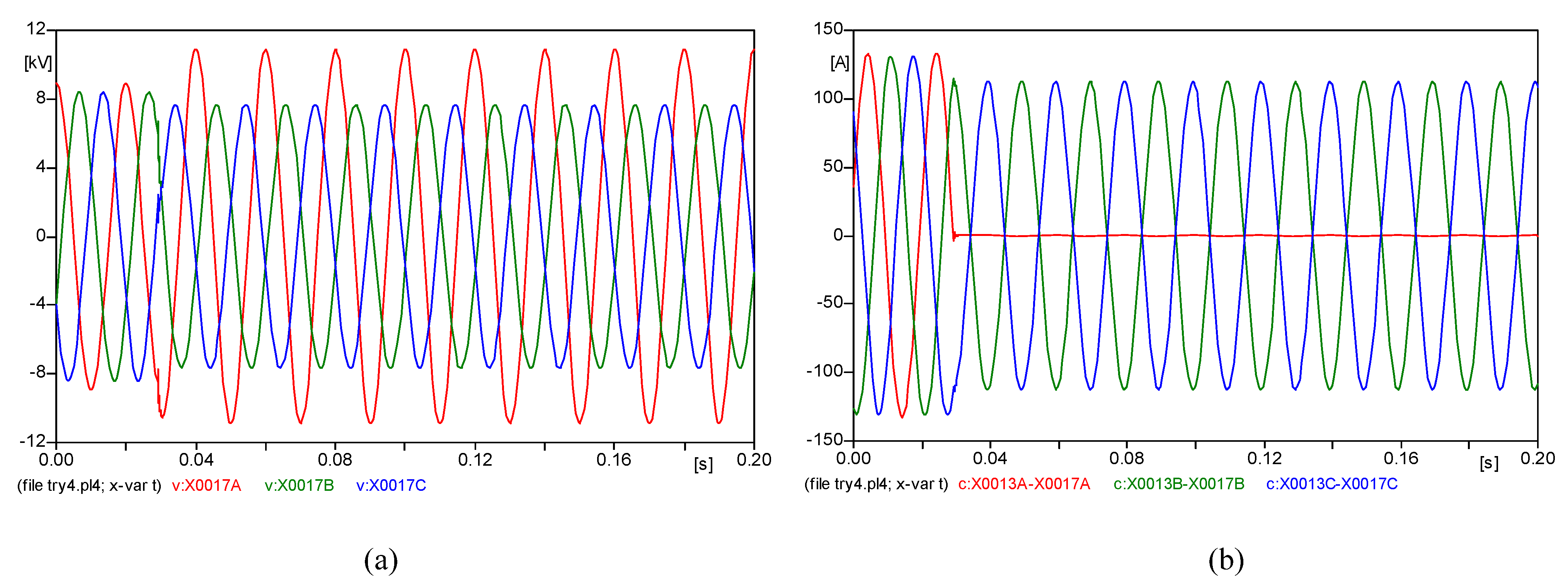
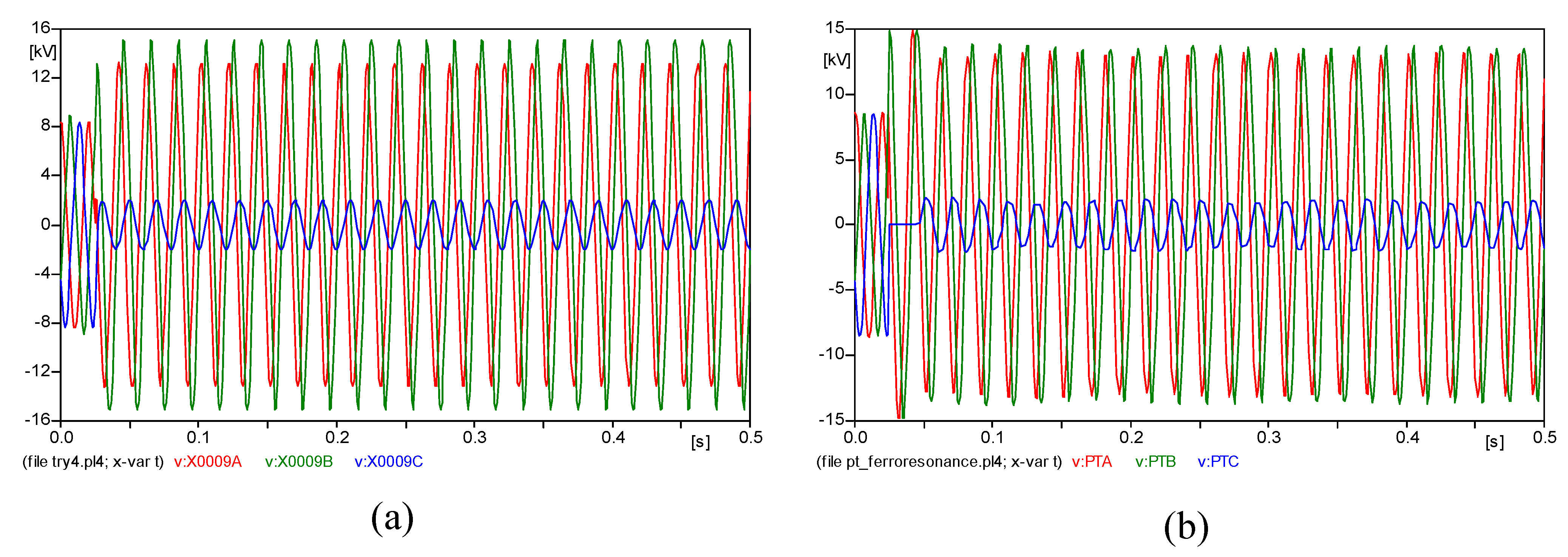
The simulation waveforms of these two kinds of power frequency over-voltages are shown as
Figure 9. It is clear that two kinds of over-voltages are very similar. This example confirms that the features of voltage are not suitable for the distinction between ground faults and power frequency ferroresonance.
Figure 9.
(a) Single phase-to-ground; (b) Fundamental ferroresonance.
Figure 9.
(a) Single phase-to-ground; (b) Fundamental ferroresonance.
In isolated neutral networks, if a single phase-to-ground takes place, the currents through loads are independent of the neutral point voltage, like when ferroresonance occurs. The current through the grounding point is the sum of three phase line-to-ground capacitive currents. If the line-to-ground capacitance is large, the fault current is also large, which makes the currents of three phase show a significant imbalance. On the contrary, if the value of the line-to-ground capacitance is small, there are no significant changes in the three-phase currents. This makes the current features not suitable for the distinction between ground faults and ferroresonance.
4. Wire Breakage
When a wire breakage occurs in isolated neutral networks, the power frequency voltages would rise too, just like in the ferroresonance and the grounding fault cases. In this paper, three kinds of common wire breakage fault are discussed, including ungrounded single-phase wire breakage, single-phase wire breakage and grounded at the supply side, ungrounded two-phase wire breakage.
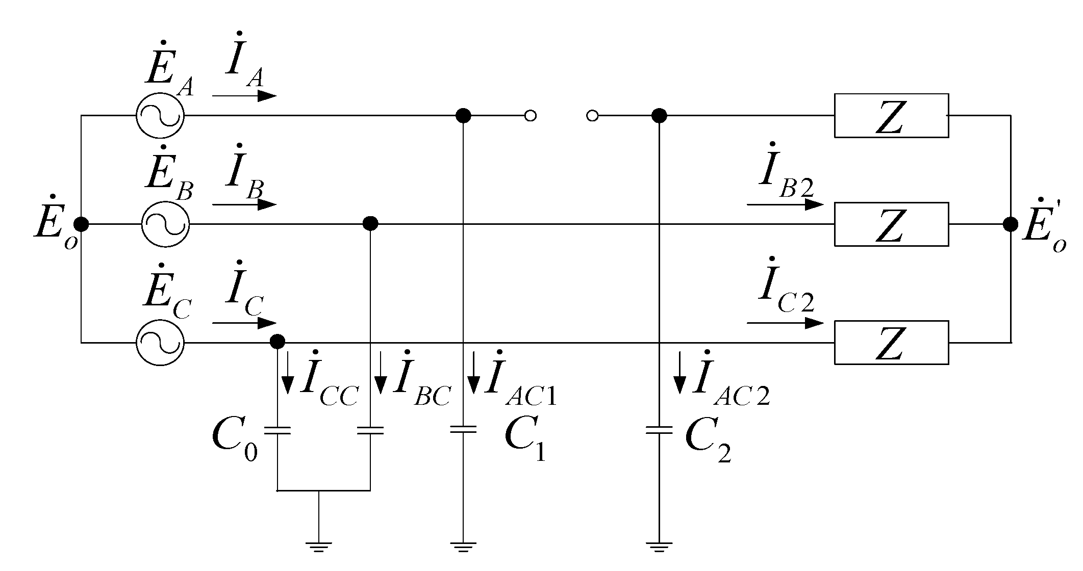
4.1. Ungrounded Single-Phase Wire Breakage
Assuming the wire breakage occurs on the phase-A, shown as
Figure 10.
C1 is the line-to-ground capacitance from supply to the wire breakage point, and
C2 is the line-to-ground capacitance from the wire breakage point to load.
C0 is line-to-ground capacitance,
C0 =
C1 +
C2.
Z is equivalent load. The neutral point voltage can be expressed as:
Figure 10.
Equivalent circuit of ungrounded single-phase wire breakage.
Figure 10.
Equivalent circuit of ungrounded single-phase wire breakage.
In practice, the value of line-to-ground capacitance
C0 is very small, using an actual substation in China as an example, the value of the equivalent load is 245 +
j9.1875 Ω, the value of line-to-ground capacitance per unit length is 0.0046 μF/km, and length of most 10 kV feeder are less then 10 km. Therefore the value of |
jωC0/
Z| can be regarded as infinitesimal. Based on this prerequisite, let the wire’s length be
d,
xd (
x = 0~1) is the distance from power supply to break point, Equation (10) can be simplified as:
The current in phase-A can be described as:
where
is the current through line-to-ground capacitance of phase-A. Because
x = 0~1, then 0 ≤ (3
x −
x2)/2 ≤ 1. Therefore, the amplitude of current in phase-A is lower than the normal line-to-ground capacitive current, and far less than the load current.
The current in phase-B is:
Similarly, Equation (13) can be simplified as:
This means that if an ungrounded single-phase wire breakage takes place, the current amplitude in non-fault phase is about 0.866 times the normal load current. A 10 kV single phase wire breakage model is built through ATP/EMTP, and three kinds of single-phase wire breakage faults (
x = 0.1, 0.5, 0.9) are simulated. Comparisons of the calculation results and simulation results are shown in
Table 1, where the value of the calculation results is obtained from Equation (11), and the value of simulation results is obtained from the ATP/EMTP software. It is clear that the results of the calculation results and simplified result are quite close. In the same way, the simplified approach of Equations (12) and (14) can be confirmed by comparing the calculation results and simplified results.
Table 1.
Comparisons of calculation results and simulation results.
Table 1.
Comparisons of calculation results and simulation results.
| Distance of Breaking Point | Amplitude of Neutral Voltage (kV) |
|---|
| Calculation Results | Simulation Results |
|---|
| 0.1 | 3.857 | 3.909 |
| 0.5 | 2.314 | 2.143 |
| 0.9 | 0.428 | 0.353 |
Limited by the length of the article, only the waveform of voltages and currents in three phase when
x = 0.5 are shown in this paper (
Figure 11).
Figure 11.
(a) Waveform of voltages; (b) Waveform of currents.
Figure 11.
(a) Waveform of voltages; (b) Waveform of currents.
4.2. Single-Phase Wire Breakage and Grounded at the Supply Side
Assuming a wire breakage occurs in phase-A, and grounded at the supply side, the neutral point voltage can be described as:
The current in phase-A can be described as:
is less than three times the normal line-to-ground current, and is also far less than the normal load current. This means that when a grounded single-phase wire breakage occurs, the amplitude of current in fault phase decreases sharply. When a single-phase wire breakage fault occurs and is grounded at the supply side, the current amplitudes in two non-fault phases drop to 0.866 times the normal load current, same as the ungrounded single-phase wire breakage fault.
4.3. Two-Phase Wire Breakage
When an ungrounded two-phase wire breakage occurs, typically, two breaking locations have the same distance from the power supply. Suppose phase-A and phase-B are broken, the neutral point voltage can be described as:
The phase-A current
and phase-B current
can be expressed as:
If
is the normal line-to-ground current of phase-A, the amplitude of
and
can be described as:
According to Kirchhoff’s first law:
It is obvious that the maximum amplitude of is less than three times the normal line-to-ground current. Therefore, when the ungrounded two-phase wire breakage occurs, the amplitudes of three phase currents will drop significantly, and far less than the normal currents.
5. Classification Criteria
5.1. Voltage Criteria
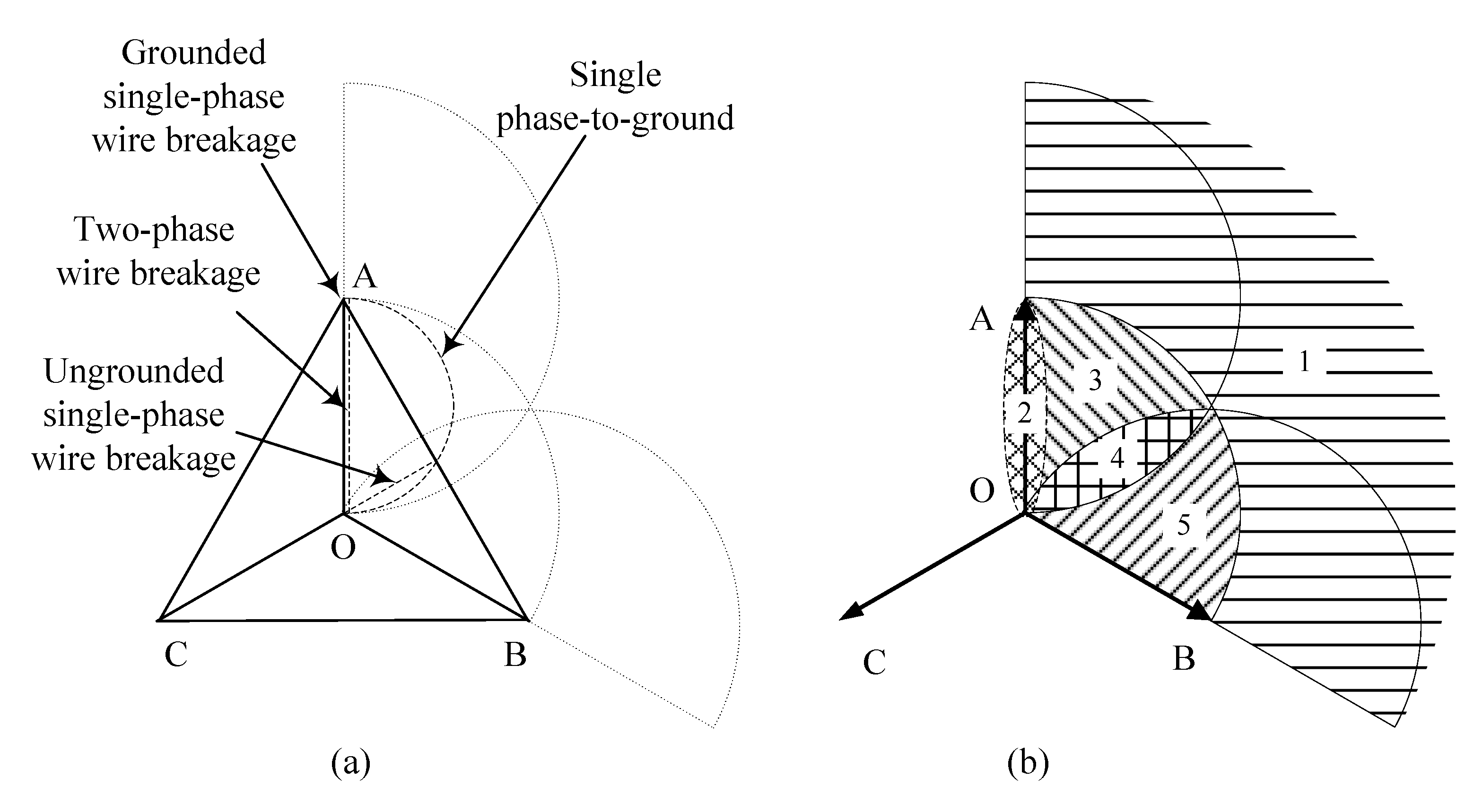
In the event of power frequency over-voltage in the networks, the amplitude and phase of the voltages are the most direct basis for classification. The possible positions of neutral-point voltage due to single phase-to-ground faults and wire breakage faults are shown as the thick dotted lines in the vector graph in
Figure 12a. The sparsely dotted lines in
Figure 12a are auxiliary circles, which are drawn with points A, B and O as the center and normal voltage amplitude as the radius.
Because the vector graph is symmetrical, in order to facilitate discussion and analysis below, we assume the location of offset neutral point O` is between vector and : .
The vector graphic is divided into five areas by these auxiliary lines, as shown in
Figure 12b. According to the position of neutral point voltage, the possible confusable over-voltages in each area are discussed below.
Figure 12.
(a) Possible position of neutral-point voltage in vector graph; (b) Divided vector graph.
Figure 12.
(a) Possible position of neutral-point voltage in vector graph; (b) Divided vector graph.
Area 1: the neutral point voltage amplitude is higher than the normal phase voltage. Comparing
Figure 12a with
Figure 12b, it is clear that the probably over-voltage of this area is:
- •
Fundamental ferroresonance
Area 2: the position of neural point voltage is on vector OA. In this area, phase-A voltage lowers, phase-B voltage and phase-C voltage rise and remain the same. The probably over-voltages are:
- •
Single-phase wire breakage and grounded at the supply side (UA = 0)
- •
Metallic grounding fault (UA = 0)
- •
Two-phase wire breakage
- •
Fundamental ferroresonance
Area 3: phase-A voltage lowers, phase-B voltage and phase-C voltage rise, but phase-C voltage is higher than phase-B. In this area the probably over-voltages are:
- •
Fundamental ferroresonance
- •
Single phase-to-ground
Area 4: phase-A voltage and phase-B voltage lower, phase-C voltage rises. In this area the probably over-voltages are:
- •
Fundamental ferroresonance
- •
Single phase-to-ground through high resistance
- •
Ungrounded single-phase wire breakage
Area 5: phase-B voltage lowers, phase-A voltage and phase-C voltage rise, but phase-C voltage is higher than phase-A. In this area the probably over-voltage is:
- •
Fundamental ferroresonance
By analyzing the voltage vector diagram, if the neural point voltage is in the areas 2, 3 and 4, the type of over-voltage cannot be distinguished just based on the features of the three-phase voltages and the neutral point voltage.
5.2. Current Criteria
Through analysis of the current features above, in the event of fundamental ferroresonance and single phase-to-ground, the currents in three-phases have no abnormal change. In the case of wire breakage, the three-phase currents display obvious changes. At least one phase current is greatly lowered. Therefore, when the current in any phase lowers greatly, the over-voltage type is power frequency over-voltage due to wire breakage, otherwise fundamental ferroresonance or single phase-to-ground. In case of ungrounded single-phase wire breakage and single-phase wire breakage with supply side grounded, both currents in fault phase are lowered greatly. Therefore, the current feature cannot be used to classify these two kinds of over-voltage, and the voltage features should be considered in the classification.
5.3. Zero Sequence Current Criterion
Fundamental ferroresonance shows a great similarity to single phase-to-ground faults. Under some conditions, the voltage and current features of fundamental ferroresonance are exactly the same as those of a single phase-to-ground fault. In a power system, the fundamental ferroresonance may confuse the ground protection system sometimes and this is why the fundamental ferroresonance can also be called as the “false ground” [
14]. In this paper, a new criterion based on phase of zero sequence current and zero sequence voltage is proposed for these two kinds of faults.
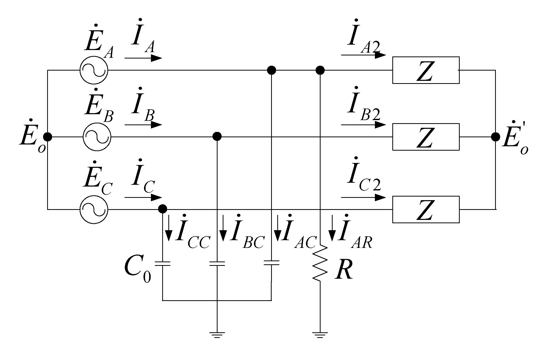
Figure 13.
Equivalent circuit of single phase-to-ground of isolated neutral network.
Figure 13.
Equivalent circuit of single phase-to-ground of isolated neutral network.
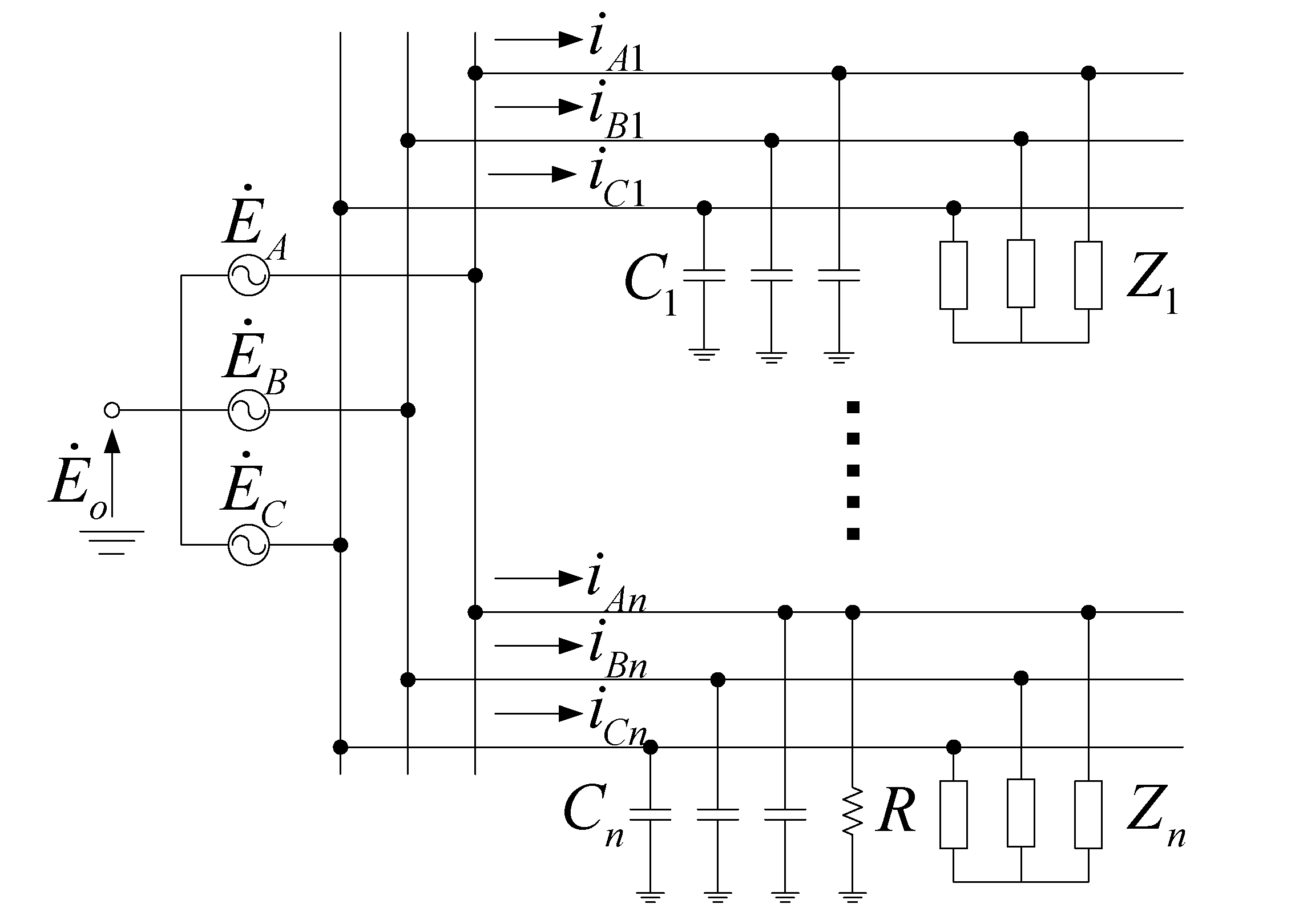
Figure 13 shows the equivalent circuit of single phase-to-ground of isolated neutral network.
C1 ~
Cn are the 1st ~
nth feeders’ line-to-ground capacitances.
Z is the equivalent load,
is the neutral voltage. The
nth feeder is grounded by resistance
R at phase-A. When the grounding fault takes place, the current through PT’s magnetizing inductance is very small, so that it can be ignored in this circuit. In this case, the zero sequence current in non-fault 1st feeder is:
This means that zero sequence current leads the zero sequence voltage by 90 degrees in the non-fault feeder. According to Kirchhoff’s first law, the sum of all leaders’ zero sequence currents is zero:
The zero sequence current of fault leader (
nth leader) can be calculated by:
This means when the single phase-to-ground fault occurs, the zero sequence current always falls behind the zero sequence voltage by 90 degrees in the fault feeder, no matter how much the grounding resistor is. When an interruption takes place in the network, such as switching or grounding, the fundamental ferroresonance could be triggered due to a PT’s nonlinear inductances saturation. The corresponding equivalent circuit is shown in
Figure 14.
Figure 14.
The equivalent circuit of PT’s ferroresonance of isolated neutral network.
Figure 14.
The equivalent circuit of PT’s ferroresonance of isolated neutral network.
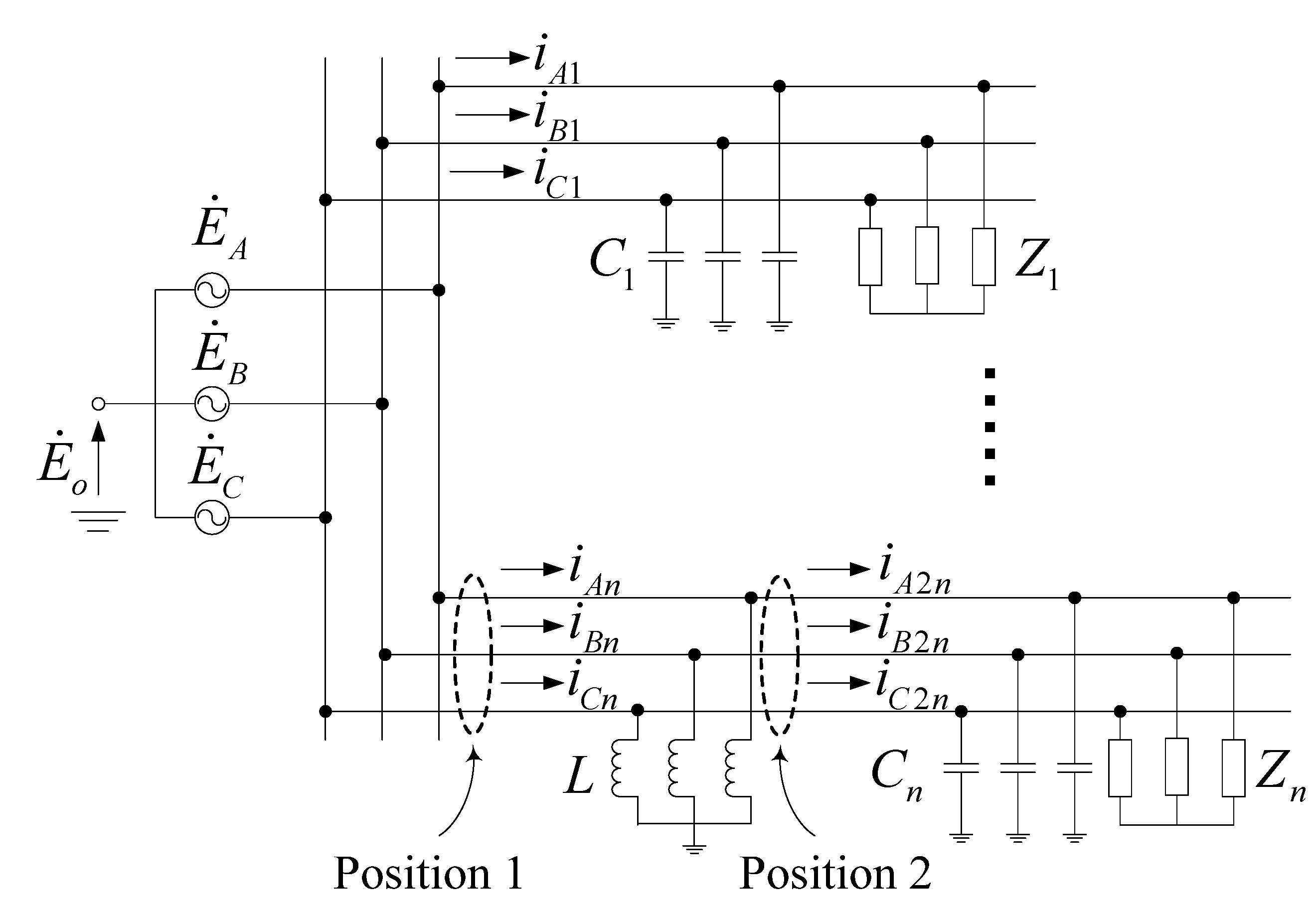
In
Figure 14, the fundamental ferroresonance occurs in the
nth feeder, the other feeders are non-fault feeders. The zero sequence current of fault leader can be described as Equation (27) too. The zero sequence current of the fault feeder still falls behind the zero sequence voltage by 90 degrees, but if the zero sequence CT is installed between the PT and the over head line (Position 2 in
Figure 14), rather than between the bus and the PT (Position 1 in
Figure 14), the zero sequence current can be described as:
This means the zero sequence current leads the zero sequence voltage by 90 degrees. It can be simply deduced that the zero sequence current leads zero sequence voltage by 90 degrees in all the non-fault feeders at this location (between the PT and the over head line). Based on this conclusion, this paper presents a new identification criterion for the fundamental ferroresonance and single phase-to-ground, which is as follows:
- •
If one feeder’s zero sequence current falls behind the zero sequence voltage by 90 degrees, and the other’s zero sequence currents lead the zero sequence voltage by 90 degrees, then the type of over-voltage is single phase-to-ground, and takes place at the feeder which’s zero sequence current fall behind.
- •
If the zero sequence current leads the zero-sequence voltage by 90 degrees in all the feeders, then the over-voltage’s type is fundamental ferroresonance.
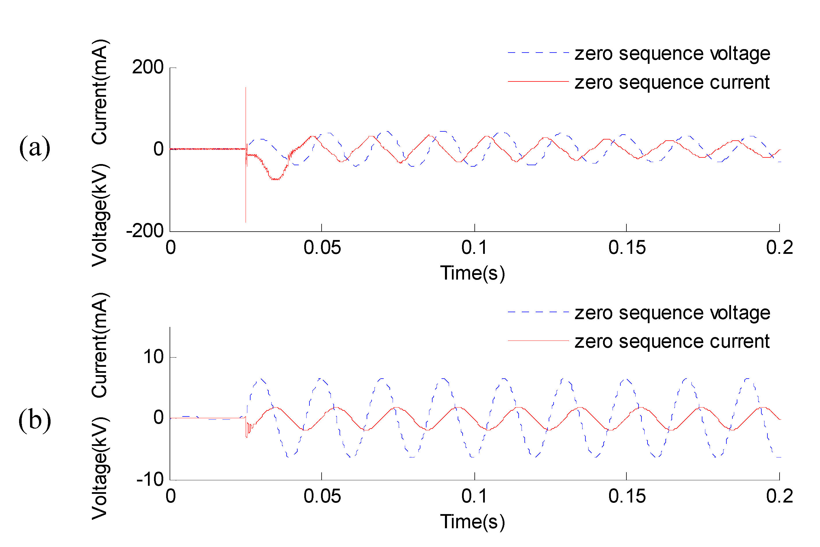
This criterion can be described in another way. If the fundamental ferroresonance due to saturation of PT’s inductor core is considered as a “false ground”, an important difference between a “false ground” and a real ground fault is that, the real ground fault takes place on the over head line, but the “false ground” takes place in the transformer substation. By installing the CT behind the PT, the “false ground” is masked out from the feeders. If the line-selection method is operated to locate the fault feeder, it would be found that all the feeders are free from faults, which means the type of current over-voltage is fundamental ferroresonance. This criterion is also verified by employing ATP/EMTP, the zero sequence voltage and current of fundamental ferroresonance and single phase-to-ground are shown in
Figure 15a,b.
Figure 15.
(a) Zero sequence voltage and current of fundamental ferroresonance; (b) Zero sequence voltage and current of single phase-to-ground.
Figure 15.
(a) Zero sequence voltage and current of fundamental ferroresonance; (b) Zero sequence voltage and current of single phase-to-ground.
6. Identification Method
6.1. Voltage Rule
6.1.1. Neutral Voltage Amplitude Rule
A characteristic quantity H
O is used to represent the amplitude feature of neutral voltage:
- •
If the amplitude of neutral voltage is greater than the normal phase voltage, then H
O = 1. (
Figure 12b, area 1)
- •
If the amplitude of neutral voltage is lower than or equal to the normal phase voltage, then H
O = 0. (
Figure 12b, area 2, 3, 4, 5)
6.1.2. Three Phase Voltage Amplitude Rule
A characteristic quantity H
ABC is used to represent the amplitude feature of voltages in three phases:
- •
If voltage amplitude in one phase rises, and the other two drop down, H
ABC = 0. (
Figure 12b, area 4)
- •
If the voltage amplitude in one phase drops, and the other two rise, then:
If the dropped voltage amplitude is equal to zero, H
ABC = 1. (
Figure 12b, area 2, point A)
If the dropped voltage amplitude is not equal to zero, and the two raised voltage amplitudes remain the same, H
ABC = 2. (
Figure 12b, area 2)
If the dropped voltage amplitude is not equal to zero, and the two raised voltage amplitudes are unequal, H
ABC = 3. (
Figure 12b, areas 3, 5)
6.2. Current Rule
A characteristic quantity C
ABC is used to represent the amplitude feature of currents in three phases:
- •
If there is one feeder, in which three-phase current amplitudes all drop and are close to zero, then CABC = 0.
- •
If there is one feeder, in which only one current amplitude of three-phase drops and is close to zero, then CABC = 1.
- •
If the three phase currents in all the feeders don’t change too much, then CABC = 2.
6.3. Zero Sequence Current Rule
A characteristic quantity C
Z is used to represent the phase relationship of zero sequence current and voltage:
- •
If all the feeder’s zero sequence current leads the zero sequence voltage by 90 degrees, then CZ = 0.
- •
If there is one feeder whose zero sequence current falls behind the zero sequence voltage by 90 degrees, then CZ = 1.
6.4. Characteristic Quantities
A 4-bit decimal number is employed as the characteristic quantity to represent the type of over-voltage. The first bit is H
O, followed by H
ABC, C
ABC and C
Z. This approach is easy extend, if new features or new types of over-voltage need to be involved, the decimal number can be easily expanded without affecting the previous classification results. The characteristic quantities of five kinds of power frequency over-voltages are shown in
Table 2. Moreover, the criteria features in this paper are extracted from the power frequency components of the three kinds of power-frequency over-voltage and over-current signals, such as the neutral voltage amplitude, three phase voltages amplitudes, three phase current amplitudes,
etc. The phase difference is also obtained from the power frequency component of zero sequence voltage and current. That is to say, the power frequency components can reflect the main characteristics of the over-voltage signals and can be successfully applied to the classification of these three kinds of power-frequency over-voltage signals.
Table 2.
Characteristic quantity for power frequency over-voltages.
Table 2.
Characteristic quantity for power frequency over-voltages.
| Characteristic Quantities | Result |
|---|
| Ho | HABC | CABC | CZ |
|---|
| 1 | * | * | * | ferroresonance |
| 0 | 0 | 1 | * | ungrounded single-phase wire breakage |
| 0 | 1/2 | 0 | * | ungrounded two-phase wire breakage |
| 0 | 1 | 1 | * | grounded single-phase wire breakage |
| 0 | 0/1/3 | 2 | 1 | single phase-to-ground |
| 0 | 0/1/2/3 | 2 | 0 | ferroresonance |
This classification method is suitable for isolated neutral networks because the main features used in classification method are proposed based on the variable neutral voltage, which is the typical characteristic of isolated neutral networks. In detail, the features can be divided into two categories: the amplitude features (voltage or current) and the phase features. For the first one, conditions of all possible system parameters are taken into account, for example the value of grounding resistance is considered from zero to infinity. For the second kind of feature, it is extracted from the phase of zero sequence voltage and current, which are independent with the system parameter. Therefore, the classification method can be used on isolated neutral networks with different network parameters.
7. Conclusions
In this paper, the voltage and current of fundamental ferroresonance, single phase-to-ground and three kinds of wire breakage faults are calculated as equivalent circuits. In order to facilitate the analysis, some complex expressions are simplified. The accuracies of all the simplified expressions are verified by comparing them with simulation results. Based on computational analysis, the most essential features and differences of five kinds of power frequency over-voltage are summed up.
Aiming at the difficulty of classification of fundamental ferroresonance and single phase-to-ground, a new identification criterion based on zero sequence current is presented in this paper. This criterion is not affected by the degree of saturation of a PT’s magnetizing inductance and the grounding resistor value, which make it suitable for field identification. By analyzing the voltage and current features of each kind of fault, a comprehensive identification method is proposed. It is feasible and promising for real applications.


