1. Introduction
The economic growth in many parts of the World during the past decade was sustainable thanks to affordable energy prices. The dependence on oil and electricity has made energy an important component in our everyday life and the recent increases of oil and gas prices have prompted everyone to take a careful look at energy issue. In the 20th century, the population has quadrupled and our energy demand went up 16 times. The exponential energy demand is exhausting our fossil fuel supply at an alarming rate [
1,
2]. About 13 terawatts (TW) of energy is currently needed to sustain the lifestyle of 6.5 billion people worldwide. By 2050, it is estimated we will need an additional 10 TW of clean energy to maintain the current lifestyle. In order to meet the increasing energy demands in the near future, we will be forced to seek environmentally clean alternative energy resources [
3,
4]. Three major options are at our disposal to tackle the generation of 10 TW of clean energy in the coming years. These include carbon neutral energy (fossil fuel in conjunction with carbon sequestration), nuclear power, and various forms of renewable energy. Among these last options, solar energy stands out as the most viable choice to meet the energy demand. Despite the vast size of this resource, the energy produced from solar sources remains less than 0.01% of the total energy demand [
5].
Nearly all energy consumed in our planet comes from the solar light, either in a roundabout way or directly in the form of heat and light radiation. The effective utilization of clean, safe, abundant and regenerated solar energy will lead to promising solutions. not only for energy issues due to the exhaustion of nature energy sources. but also for many problems caused by environmental pollution. Sunlight can be converted into other forms of energy by a variety of methods. Generally speaking, the first step to utilize solar light is conversion, by which we can use it in our own way. The second is storage, by which we can store excess energy in the day time and use it during the night or any other time when the visible light available is insufficient.
Photoelectric conversion is one of the most widely-used and well-developed techniques in the field of solar energy utilization today. The photovoltaic (PV) industry is booming, with an estimated growth rate in excess of 30% per year over the last decade [
6]. Crystalline silicon solar cells, which are presently demonstrated to have energy conversion efficiencies close to 25%, account for the most important part of the world PV market [
7,
8]. Dye sensitized solar cells, which have already reached conversion efficiencies exceeding 11%, offer the prospect of the low cost fabrication without expensive and energy-intensive high temperature and high vacuum processes to facilitate market entry [
9]. Thin film PV technologies based on inorganic materials are developing rapidly both in the laboratory and in industry [
6]. They are also a formidable competitor aiming to boost their market share.
However, these traditional photovoltaic materials generally function as photoelectric or chemical energy conversion devices under irradiation. The excess energy produced by these devices has to be stored by energy storage systems such as electrochemical storage cells or supercapacitors [
10]. The existence of the energy storage systems always results in an increase of expense and the consumption of extra energy. Now that traditional photovoltaic materials cannot play the role of energy storage and traditional energy storage systems do not have the ability of photoelectric conversion, their combination should be a new promising field in the development and utilization of solar energy.
TiO
2 nanostructure hybrid materials are the focus of both fundamental and applied research [
11]. Nanohybrid materials developed by the modification of pristine TiO
2 with anions, cations, and metals are named second-generation TiO
2 photocatalysts [
12]. Electron transfer between a TiO
2 substrate and the interfused material endows them with novel properties, such as absorption of visible light and enhanced light electricity conversion efficiency and improved activity in photocatalysis [
13,
14,
15], which can be used in quantum dot solar cells [
16,
17] and gas sensors [
18]. In recent years, functionalized TiO
2 hybrid materials were also reported as energy storage materials.
In 2000, Zou’s group found that TiO
2/carbon fiber electrodes prepared by laser deposition had dual functions of opto-electric conversion and electrochemical energy storage. Since 2001, a few Japanese research groups have developed several TiO
2 composite systems with dual abilities of photoelectric conversion and energy storage (bifunctional composite system) and a few similar TiO
2 composite systems were developed in recent years by other groups. This is a very new research field that has not yet been paid the deserved attention. Incidentally, the application for TiO
2 composite system in solar energy has been overviewed extensively [
9,
19,
20], but that for both photoelectric conversion and energy storage of solar energy has not yet been reviewed until now. So, according to the publications and the research carried out in our laboratory, a general overview of the subject of energy storage in TiO
2 composite systems under solar light is presented here.
2. Survey of Bifunctional TiO2 Composite Materials
In 2000, TiO
2 composite materials with energy storage abilities were first developed by Xinjing Zou’s group [
21] who found that TiO
2/carbon fiber electrodes functioned as a photo-rechargeable battery with the dual functions of opto-electric conversion and electrochemical energy storage. In 2001, Tatsuma
et al. [
22] developed a TiO
2/WO
3 photoelectrochemical anticorrosion system with energy storage ability. A TiO
2 coating is coupled with a WO
3 coating as an electron pool, in which the reductive energy can be stored. Snce then, TiO
2/MoO
3 [
23], SrTiO
3/WO
3 [
24], TiO
2/phosphotungstic acid (PWA) [
25], TiO
2/Ni(OH)
2 [
26] and several other TiO
2/WO
3 [
27,
28,
29] composite systems have also been developed by the groups of Tetsu Tatsuma and his collaborators. The energy can be stored either in reduced WO
3, MoO
3, PWA or in oxidized Ni(OH)
2 under UV light. In 2003, Raghavan
et al. [
30] showed that SnO
2 coupled with TiO
2 can store reductive energy generated on UV illumination of TiO
2, which enables the continued cathodic protection effect under dark conditions. In 2008, Yasomanee
et al. [
31] reported that TiO
2/Cu
2O composite films showed a multi-electron storage ability under UV-vis irradiation. It was noticed that the irradiation of ITO/TiO
2/Cu
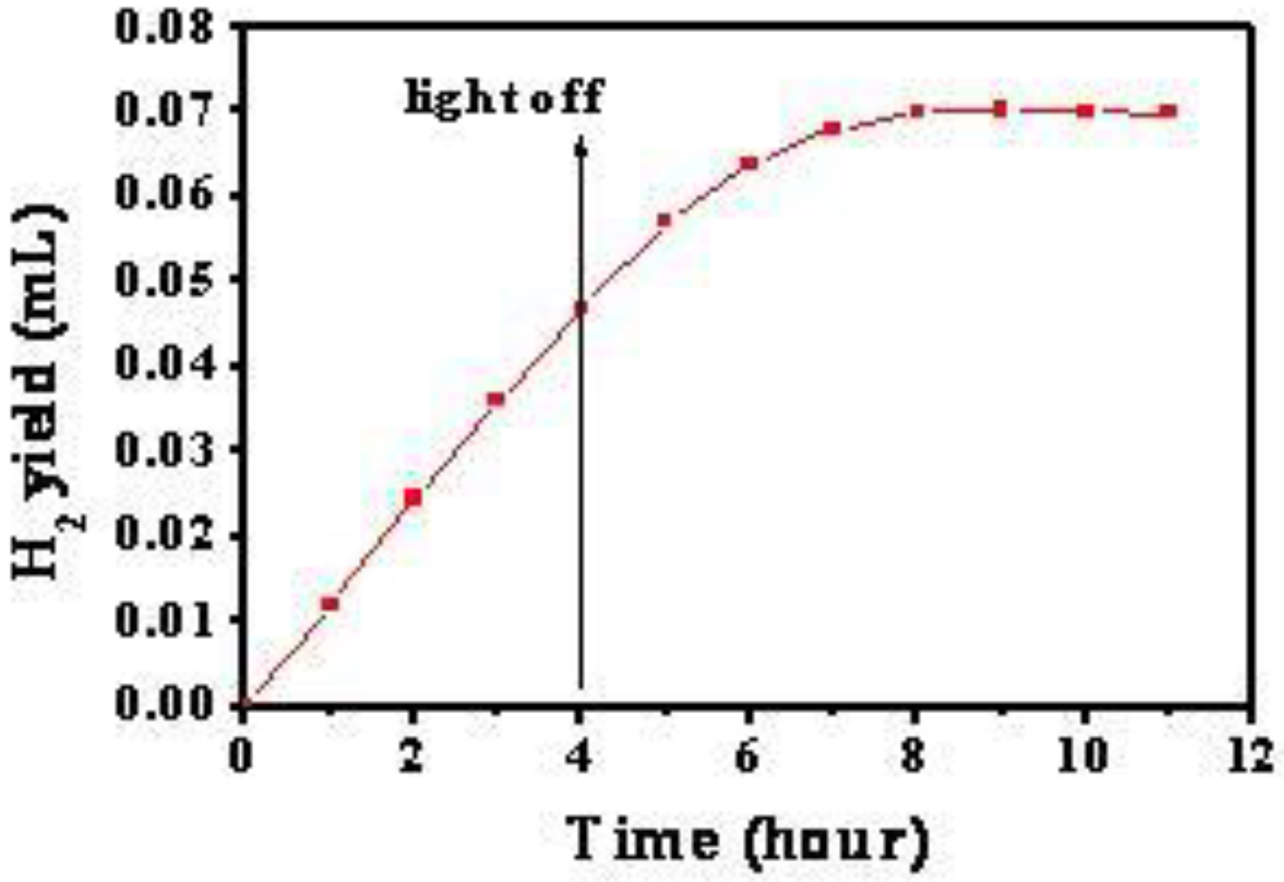
2O led to the formation of trapped electrons and this stored energy resulted in H
2 evolution from H
2O, even in the dark. Additionally, Chien-Tsung Wang [
32] demonstrated that V
2O
5 served as an energy storage material to accumulate photoelectrons generated by the TiO
2 semiconductor, due to the relative energy levels of the conduction bands of V
2O
5 and TiO
2. In 2009, Zhang’s [
33], Zhao’s [
34] and Tatsuma’s [
35] groups reported that optical energy can be stored by TiO
2 nanotube array/Ni(OH)
2 composite electrodes, WO
3/TiO
2 nanohybrid materials and Au–TiO
2/WO
3 systems, respectively. It is worth mentioning that the Au–TiO
2 composite system, which is based on plasmon resonance absorption of Au nanoparticles, can store reductive energy in WO
3 under visible-light irradiation. Recently, our group found that visible-light energy can be stored by Ti
3+ in TiO
2/Cu
2O bilayer film [
36]. The appearance of visible-light induced energy storage system is a significant progress in this field and beneficial practical application since it can work directly under solar light.
3. Working Mechanism of Optical Energy Storage
The energy can be stored by reduced materials (such as WO3,MoO3 and PWA), oxidized ones (Ni(OH)2) or TiO2 itself. Zou’s group described the double functions of opto-electric conversion and electrochemical energy storage for TiO2/carbon fiber electrodes by the characterization of photo charge and discharge currents. The systematic research on the mechanism of optical energy storage was first done by Tatsuma’s group. Based on their and our own work, we here introduce three representative optical energy storage mechanisms.
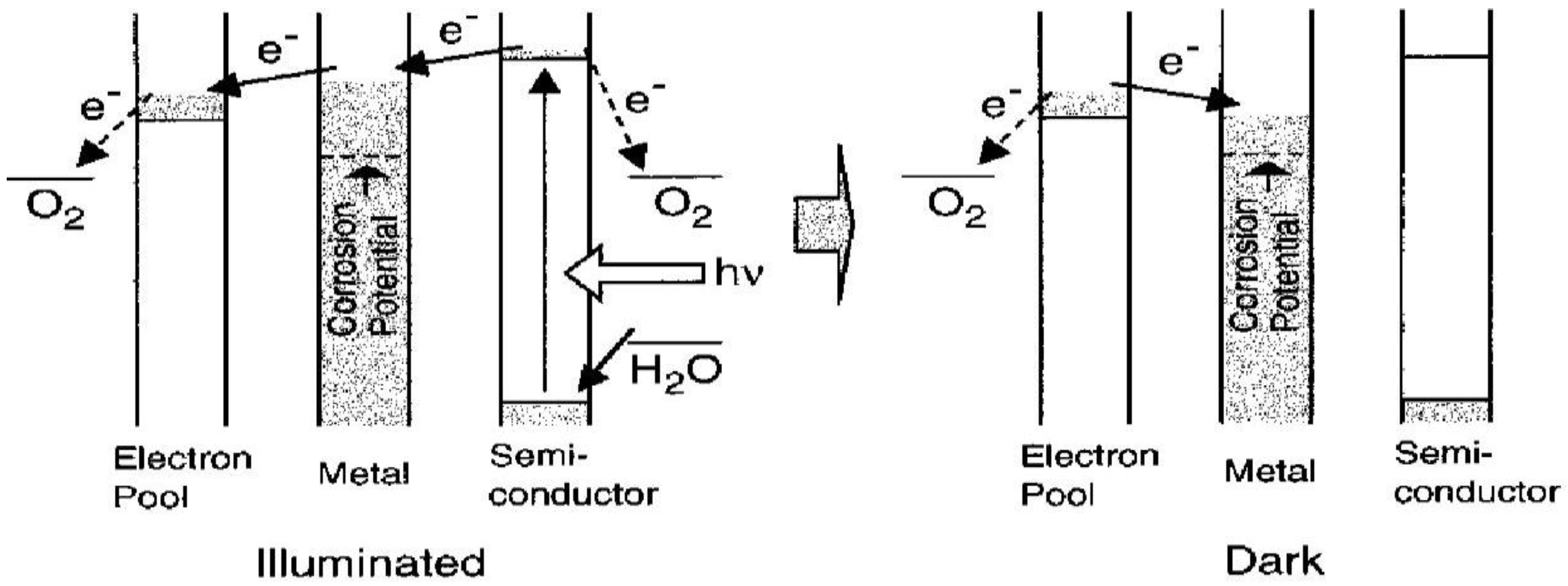
3.1. Reductive Energy Storage in TiO2/WO3 (MoO3 or PWA) Composite System
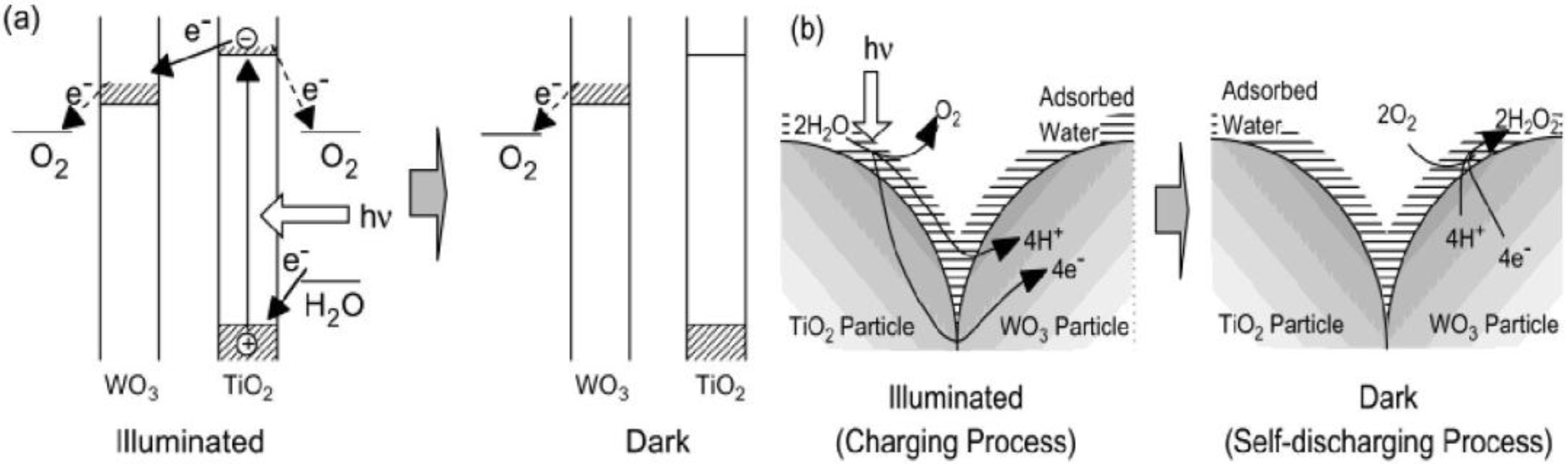
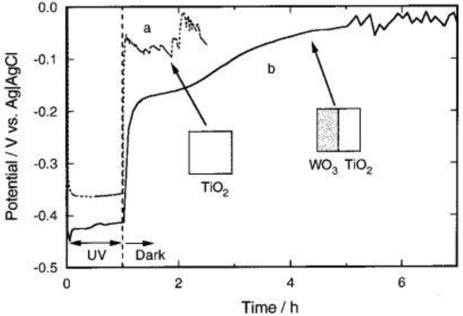
Figure 1 shows the mechanism of reductive energy storage by TiO
2/WO
3 composite system [
27]. In this system, an excited electron and a corresponding hole are generated on TiO
2 under UV light:
The electron may be transported through TiO
2 (n-type semiconductor) to WO
3, and if so, a cation should be intercalated into WO
3. In pure water, only H
+ is available as a cation:
On the other hand, the hole should also be consumed at the TiO
2 surface by H
2O to generate chiefly O
2 and H
+. Thus, H
+ is generated by TiO
2 (Equation 3) and is consumed by WO
3 (Equation 2):
Figure 1.
(a) Mechanism of reductive energy storage of TiO
2/WO
3 composite system [
28]. (b) Proposed models of electron and ion transfer in the charging and self-discharging processes of the TiO
2/WO
3 composite film in humid air [
27].
Figure 1.
(a) Mechanism of reductive energy storage of TiO
2/WO
3 composite system [
28]. (b) Proposed models of electron and ion transfer in the charging and self-discharging processes of the TiO
2/WO
3 composite film in humid air [
27].
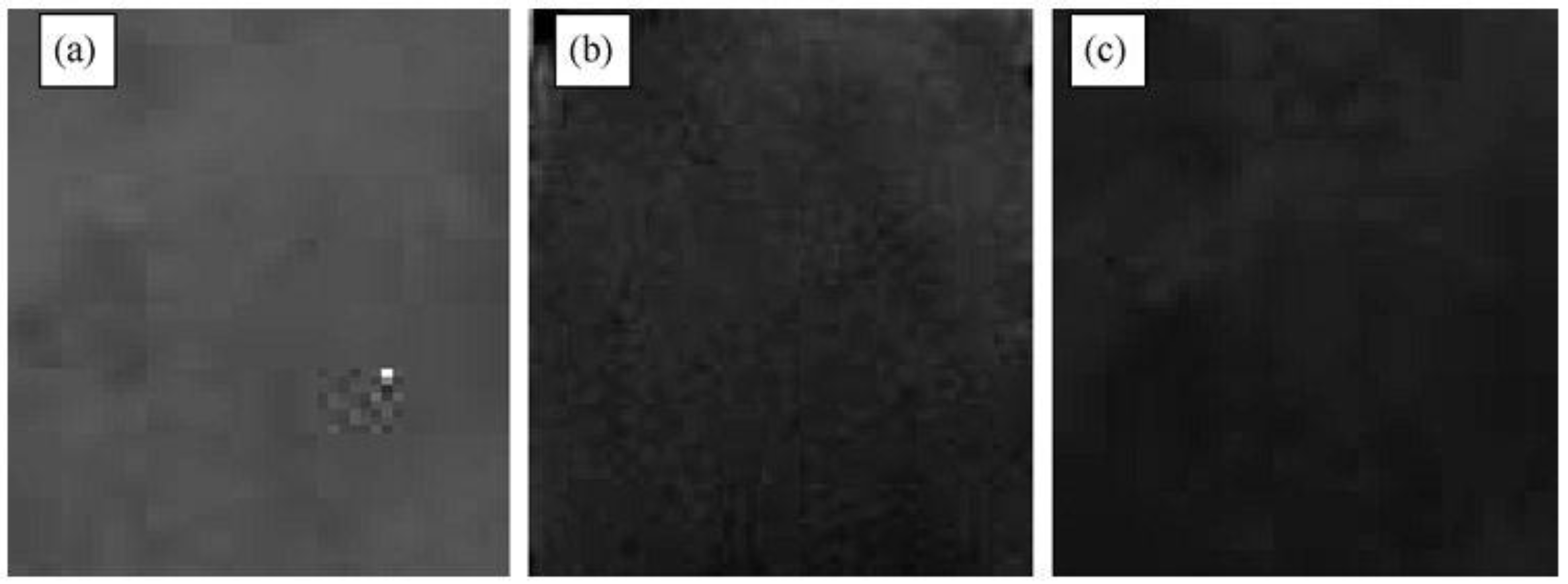
The ITO electrode coated with the TiO
2/WO
3 composite film (type b, thick film,
Figure 2a) was subjected to the 1 h UV irradiation in air to show the formation of H
xWO
3. As shown in
Figure 2b, the behavior strongly depended on the relative humidity of the atmosphere. The film was well-colored in a humid atmosphere (relative humidity ≥25%), while it was not colored well in a dry atmosphere. The color of H
xWO
3 is blue. The reduction of WO
3 (almost colorless) gave rise to the decrease in the reflectance shown in
Figure 2b.
This can be explained in terms of ionic conductivity of the film surface. In the humid atmosphere, an adsorbed water layer should form on the film surface. This layer and the surface hydroxyl groups, of which dissociation should be facilitated by this water layer, should contribute to the ionic conduction. It is necessary for the photoelectrochemical reduction of WO
3 (
Figure 1b). To the contrary, in the dry atmosphere, the adsorbed water layer is almost absent so that the ionic conductivity should not be sufficient for the WO
3 reduction.
As the excess electrons are accepted by WO
3 and more H
xWO
3 is generated, the reductive energy can be stored by WO
3 in pure water, humid air or solution. It can be seen that WO
3 retains the reductive energy for a certain period even after the light is turned off (
Figure 1a).
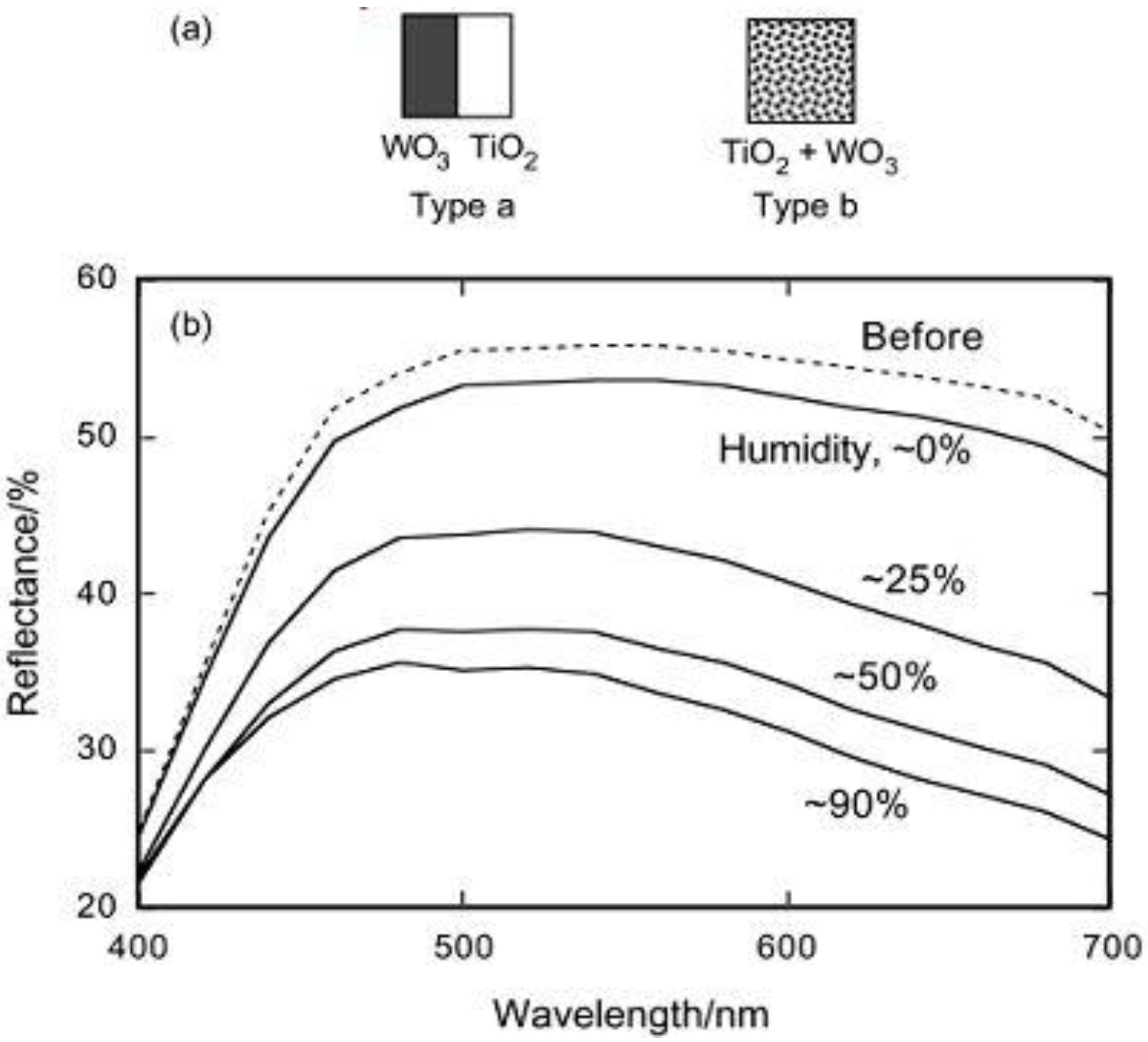
Figure 2.
(a) Schematic models for TiO
2/WO
3 separated films (type a) and TiO
2/WO
3 composite film (type b). (b) Changes in the reflectance of the TiO
2/WO
3 composite film (type b, thick film) after UV irradiation (22 mW cm
−2, 20 min) at a relative humidity of about 0, 25, 50, and 90% [
27]. Reproduced with permission from the ACS, ©2002.
3.2. Oxidized Energy Storage in TiO2/Ni(OH)2 Composite System
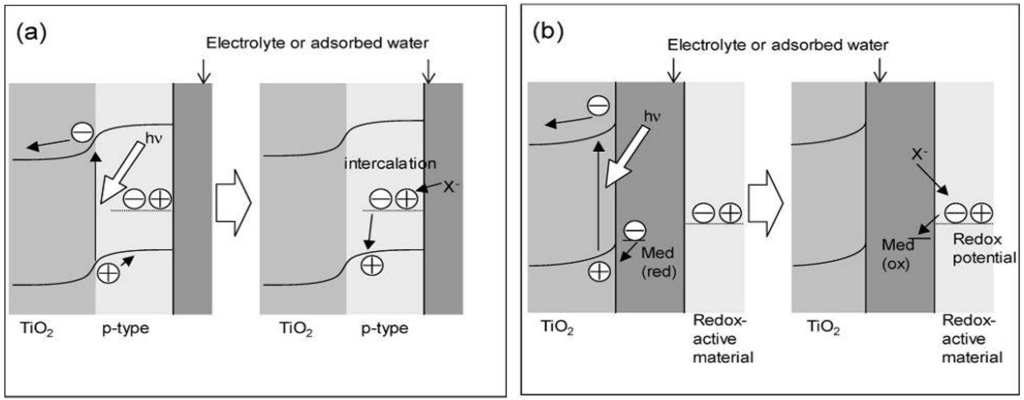
Two kinds of models for storing the oxidative energy of TiO
2 were proposed, the p-n junction model and the mediation model (
Figure 3) [
26]. In the former, a redox-active p-type semiconductor is combined with TiO
2 to form a p-n junction (
Figure 3a).
Holes generated at the junction are separated from excited electrons and transported into the bulk of the p-type semiconductor for the oxidative energy storage. The electrical neutrality will be retained by the intercalation of the anions or the deintercalation of the cations so that oxidative energy will keep stable. In the mediation model (
Figure 3b), an oxidant like O
2, which is photocatalytically produced by the oxidation of water adsorbed on TiO
2, diffuses and oxidizes a redox-active material.
Figure 3.
Models for the oxidative energy storage photocatalysts. (a) p-n junction model and (b) mediation model [
26].
Figure 3.
Models for the oxidative energy storage photocatalysts. (a) p-n junction model and (b) mediation model [
26].
Ni(OH)
2 is reported to be a p-type semiconductor [
37,
38], and is known as a cathode active material of secondary batteries [
39] with relatively positive redox potential (+0.5 to +0.6 V vs Ag|AgCl). Therefore, it is expected to be suitable for oxidative energy storage. After a TiO
2/Ni(OH)
2 bilayer film was irradiated with UV light (365 nm; 10 mW cm
−2) in pH 10 buffer, the film turned to brown as did the electrochemically oxidized film. Actually, the visible absorption spectrum of the irradiated film looked like that of the electrochemically oxidized film. These results suggest that the irradiation gave rise to the oxidation of Ni(OH)
2. However, a Ni(OH)
2 film without TiO
2 was not colored under UV-irradiation. Therefore, TiO
2 should contribute to the photooxidation of Ni(OH)
2. The brown-colored film could be turned back to colorless by electrochemical reduction. Namely, the photoelectrochemically stored oxidative energy could be taken out and used.
The photooxidation of Ni(OH)
2 most probably proceeds as follows. Electrons are photoexcited from the valence band to the conduction band (e
−CB) in TiO
2 or at the TiO
2/Ni(OH)
2 junction (Equation 1). The correspondingly formed holes in the valence band (h
+ VB) accept electrons from Ni(OH)
2, either directly or indirectly (Equation 4):
The photo-excited electrons should be consumed by an electron acceptor, most likely dissolved oxygen diffused to the TiO
2 surface through the pores in the Ni(OH)
2 layer because of a reaction such as Equations 5a or 5b:
At the current stage, it is uncertain whether the oxidative energy storage is based on the p-n junction model (
Figure 1a) or the mediation model (
Figure 1b). According to the literature [
40], TiO
2 is known to form a p-n junction with NiO. Ni(OH)
2 is also reported to be a p-type semiconductor similar to NiO [
30]. Hence, it is possible that a p-n junction forms at the TiO
2/Ni(OH)
2 interface. If the mediation model worked, the mediator might be, for example, the H
2O
2 generated by Equation 5b. However, a Ni(OH)
2 film without TiO
2 was not oxidized when it was exposed to 0.1–10 M H
2O
2 with or without UV light. Rather, oxidized Ni(OH)
2 was reduced by H
2O
2 in the dark. Thus, the mediator, if any, is more likely to be an oxidant other than H
2O
2. If the energy storage proceeded according to the p-n junction model, the efficiency would be improved by increasing the junction area, for instance, by making the TiO
2 layer porous. On the other hand, if the mediation model worked, the distance between Ni(OH)
2 and TiO
2 could be optimized so as to suppress the rereduction by the electrons on TiO
2.
In all, although it is uncertain whether the oxidative energy storage is based on the p-n junction model or the mediation model, it is sure that the energy stored in Ni(OH)2 is oxidized energy, which is different from that in WO3 according to their color changes and results of photoelectrochemical experiments.
3.3. Multi-electrons Energy Storage in TiO2/Cu2O Composite System
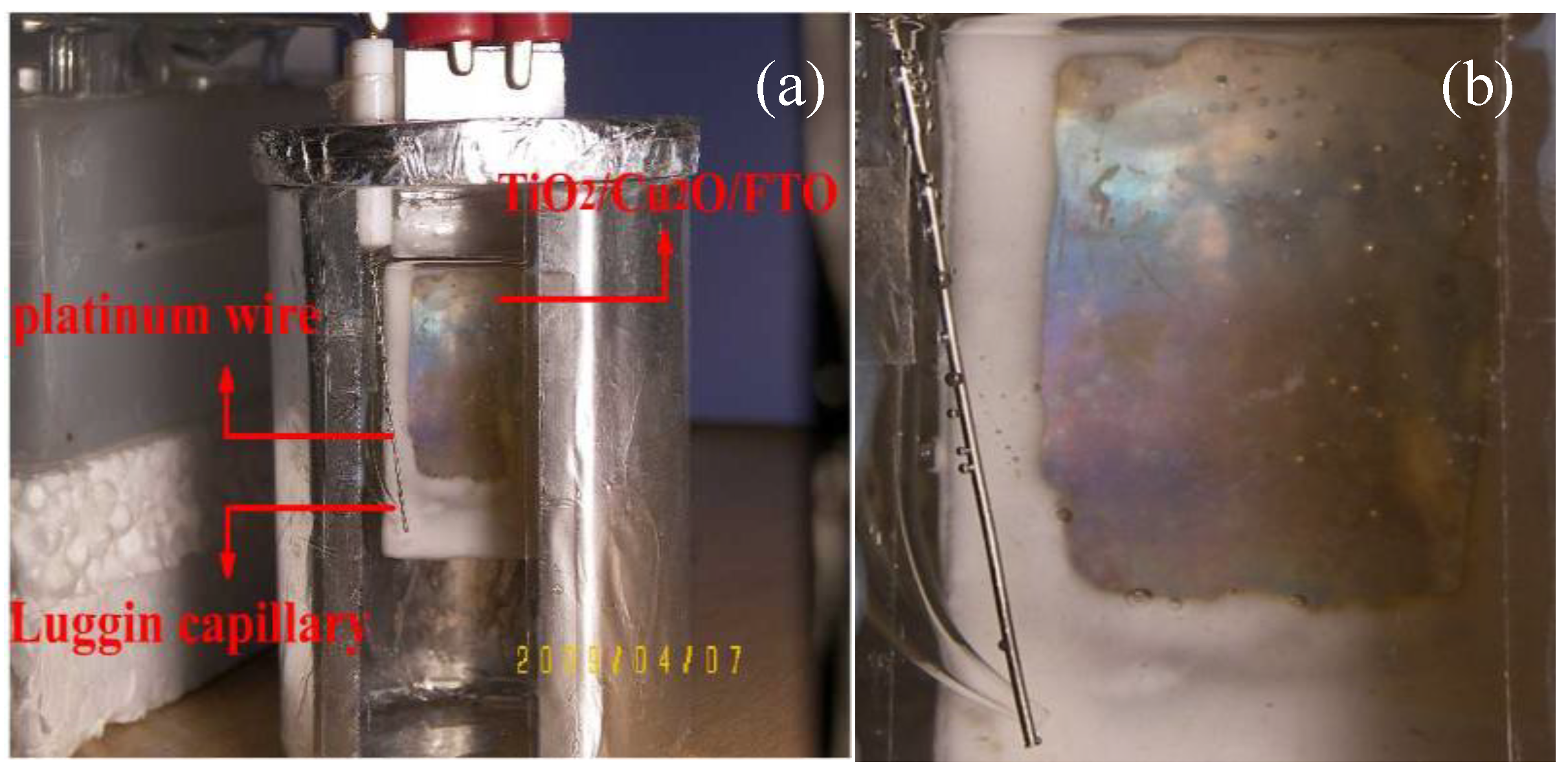
Recently, we prepared a TiO
2/Cu
2O bilayer film on doped fluorine SnO
2 (FTO) conducting glass according to literature [
41,
42]. Ti
3+ in the TiO
2/Cu
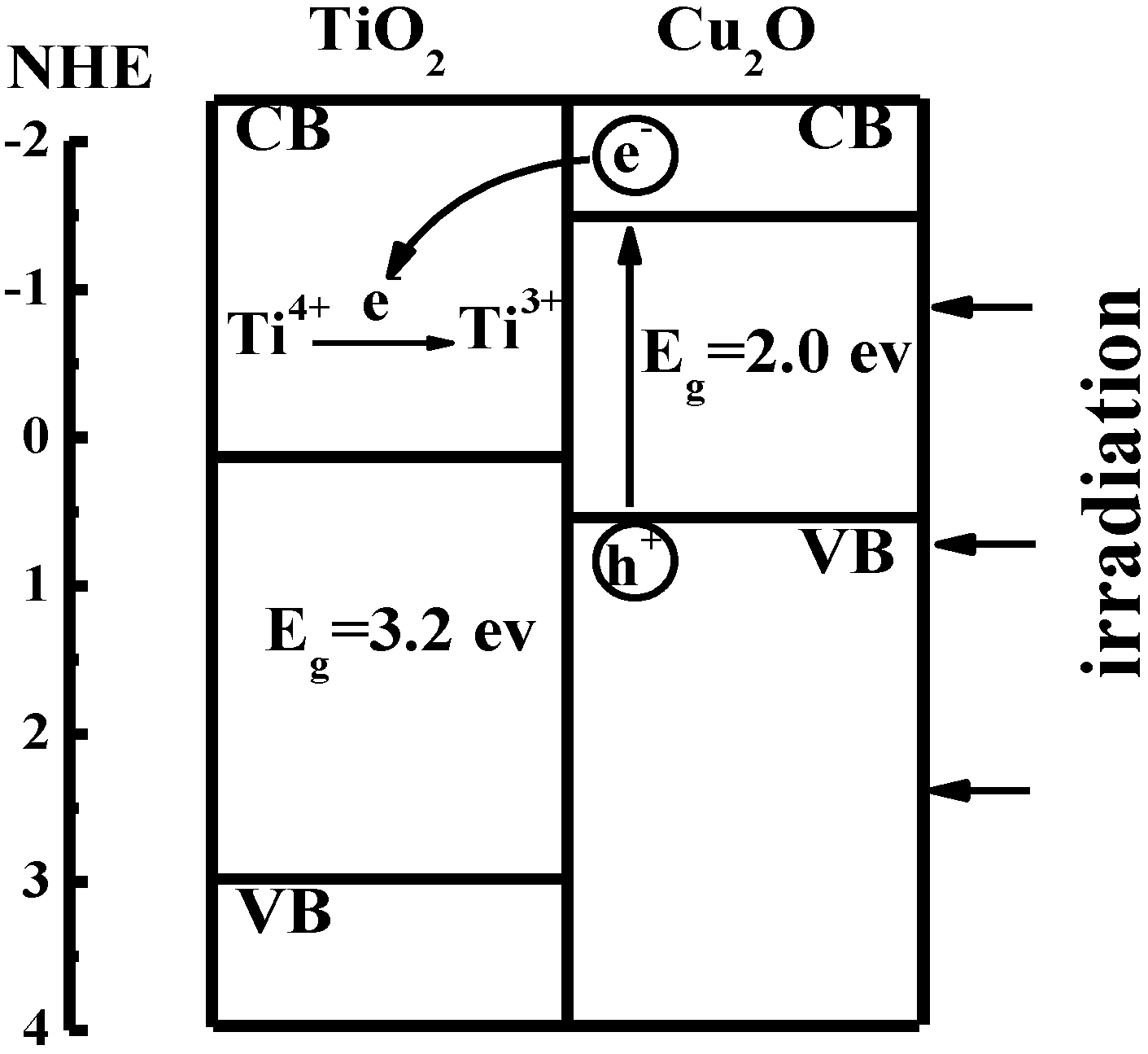
2O bilayer film is demonstrated to store energy under visible light. It is well known that the band gap of TiO
2 is about 3.2 eV and the conduction band of TiO
2 is about –0.2 eV [
43]. Cu
2O is a semiconductor with one of the highest conduction bands. The band gap of Cu
2O is about 2.0 eV and the potential of its conduction band is –1.4 eV [
44].
Figure 4.
Sketch of interfacial electron transfer in TiO
2/Cu
2O bilayer film [
36].
Figure 4.
Sketch of interfacial electron transfer in TiO
2/Cu
2O bilayer film [
36].
As shown in
Figure 4, the photogenerated electrons from the conduction band of Cu
2O were captured by Ti
4+ ions in TiO
2 and Ti
4+ ions were further reduced to Ti
3+ ions. The Ti
3+ ions have a long lifetime and bear the photogenerated electrons as a form of energy. The electron transfer process is shown in Equations 6 and 7:
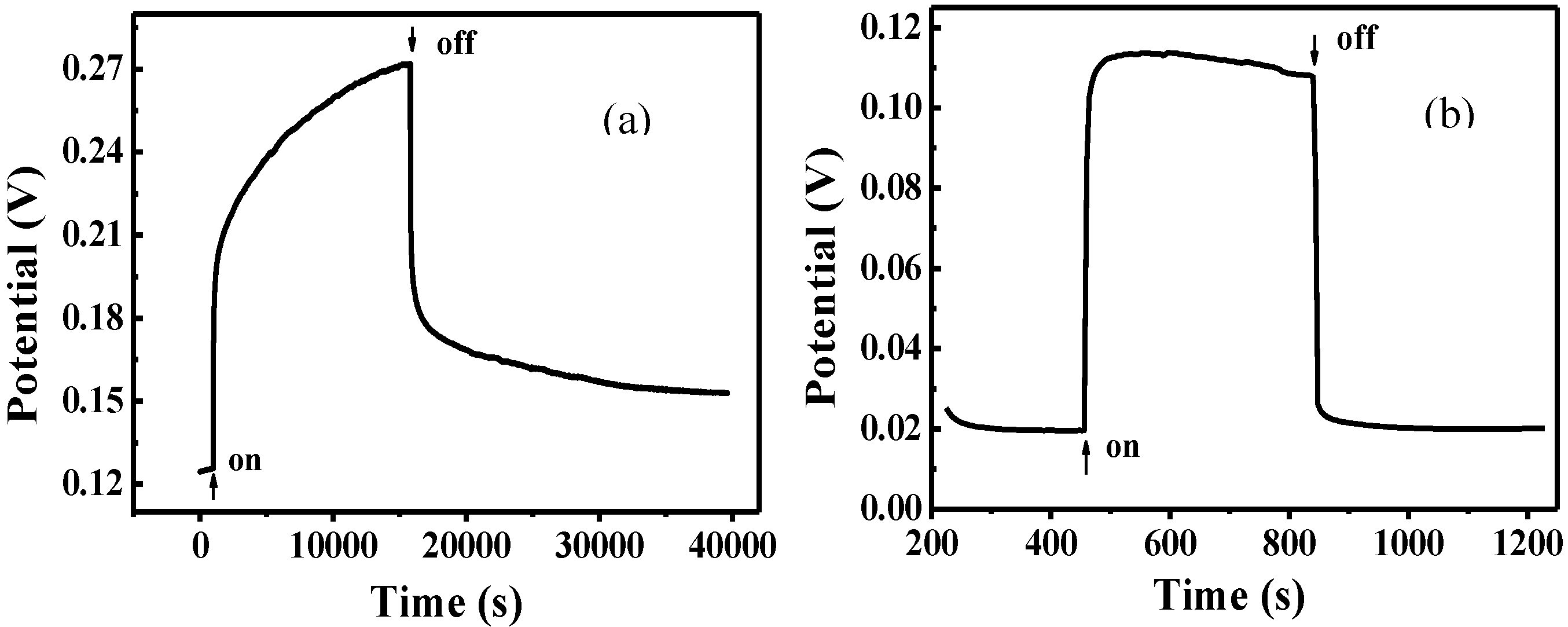
The photovoltage measured as a function of time under visible-light irradiation for FTO/TiO
2/Cu
2O and FTO/Cu
2O electrodes is shown in
Figure 5. It can be seen that the potential for both of the two electrodes shifted positively under the same irradiation. The positive potential shift could be due to hole generated on Cu
2O, which is one of p-type semiconductors. As TiO
2 has no response to visible light, the photopotential of TiO
2/Cu
2O bilayer film almost results from Cu
2O. So, just like Cu
2O electrode, the potential shift of the TiO
2/Cu
2O electrode should be similar to that of Cu
2O. This result is similar to the report in [
32]. The net positive photovoltage results from the interfacial potential difference of electrostatic double layer formed between holes on the surface of Cu
2O and SO
42− layer in the electrolyte.
Figure 5.
Photovoltage measured as a function of time for FTO/TiO
2/Cu
2O (a) and FTO/Cu
2O (b) electrodes [
36].
Figure 5.
Photovoltage measured as a function of time for FTO/TiO
2/Cu
2O (a) and FTO/Cu
2O (b) electrodes [
36].
Moreover, the potential for the FTO/Cu2O electrode jumped to the maximum instantly and remain unchanged. It indicates that the generation and recombination of e−-h+ pairs in Cu2O established a dynamic equilibrium. However, it took the FTO/TiO2/Cu2O electrode about four hours to reach its maximum. It indicates that there was a process for the accumulation of holes in FTO/TiO2/Cu2O electrode. Since photogenerated electrons and holes were produced in Cu2O under the irradiation, it can be proposed that there was a process for the accumulation of electrons in FTO/TiO2/Cu2O electrode. The photogenerated electrons in Cu2O have much energy due to the absorption of visible light. Thus, when these electrons are transferred to the conduct band of TiO2 and trapped by Ti4+, they are seen as Ti3+ and are stored as a form of energy in the bilayer film. The holes still stay in Cu2O. The longer the irradiation time, the more electrons were generated by Cu2O and injected into TiO2 and thereafter the more energy stored. This process did not stop until the potential of the TiO2/Cu2O electrode reached the maximum.
After the irradiation was removed, the potential for both of these electrodes shifted negatively. The potential for FTO/Cu2O electrode dropped instantly to the minimum, the original potential before the irradiation. It indicates that the photogenerated electrons and holes are recombined completely. However, it took FTO/TiO2/Cu2O electrode a long time to reach its minimum, which was still higher than the original potential before the irradiation. It indicates that there are still holes in FTO/TiO2/Cu2O electrode and the photogenerated electrons and holes may not be recombined completely because a little amount of electrons are still trapped by Ti3+.
Additionally, under the same irradiation, the potential increment for FTO/TiO2/Cu2O electrode was much higher than that for FTO/Cu2O electrode. It demonstrates that much more photogenerated holes and electrons were present in the bilayer film. The better photoelectric properties of the bilayer film than that of Cu2O film suggests that the bilayer films have improved abilities for charge separation and charge carrier lifetime, and can store energy.
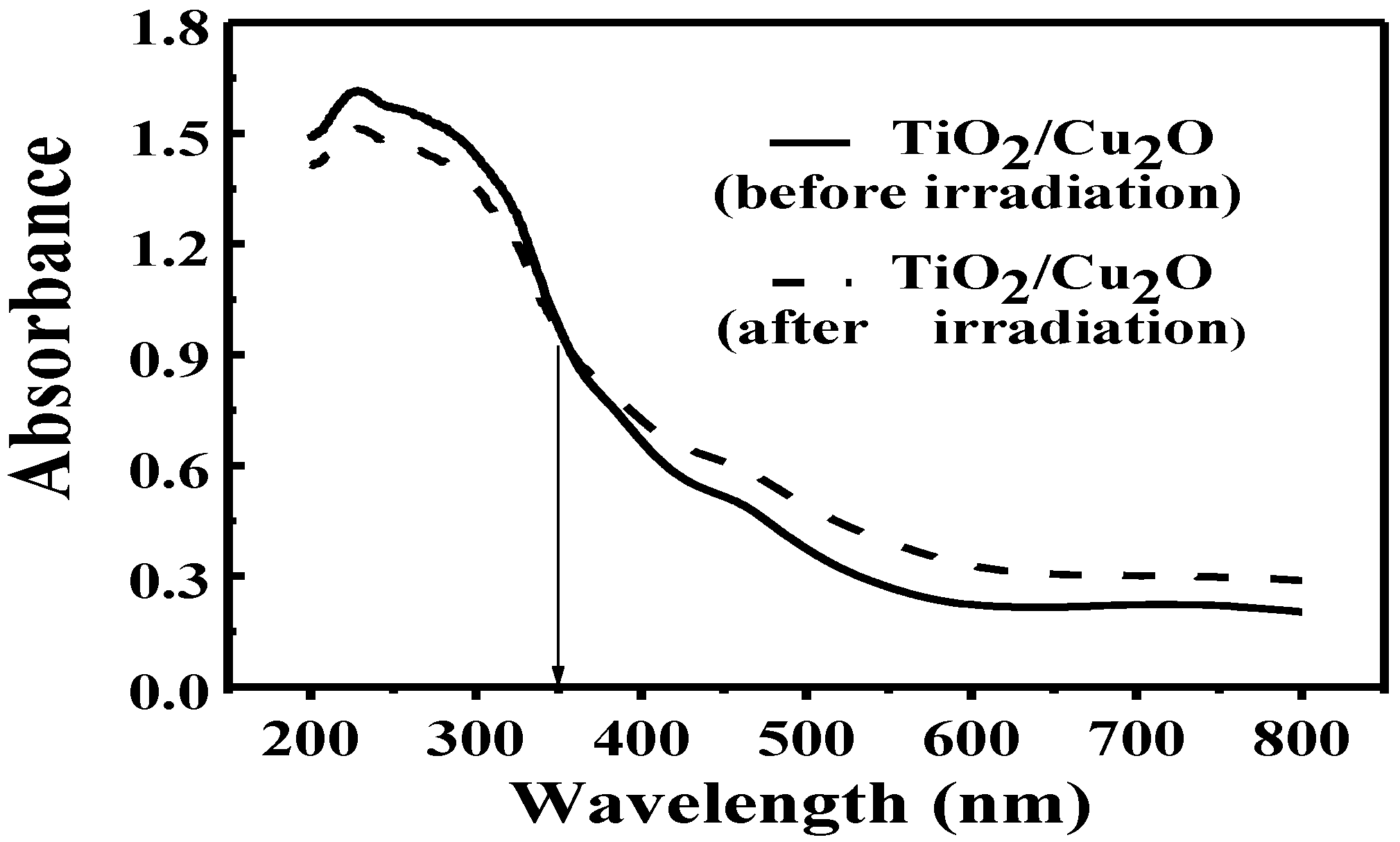
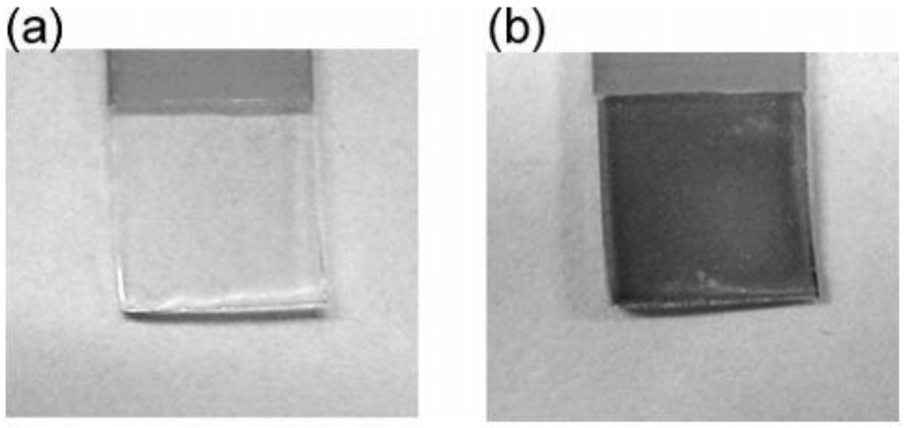
UV-vis diffuse reflectance measurements were further carried out to identify the conversion of Ti
4+ to Ti
3+ in the bilayer film after the irradiation. As shown in
Figure 6, the absorbance of the bilayer film became weaker in the short wavelength range (200 nm ≤ λ ≤ 350 nm) while becoming stronger in the long wavelength range (350 nm < λ ≤ 800 nm) after the irradiation. It is confirmed based on the above data that Ti
3+ ions were produced in the bilayer film after the irradiation. Because Ti
4+ has no response to visible light while Ti
3+ does [
45,
46,
47], the presence of Ti
3+ ions leads to the weaker absorbance of bilayer film in the short wavelength range while stronger in the long wavelength range. It is found that the transparent TiO
2 film turned blue under the irradiation. The phenomenon is similar to Yasomanee’s report [
31] and also demonstrates the presence of Ti
3+.
Figure 6.
UV-vis diffuse reflectance spectra of TiO
2/Cu
2O bilayer film before (solid line) and after irradiation (dashed line) [
36].
Figure 6.
UV-vis diffuse reflectance spectra of TiO
2/Cu
2O bilayer film before (solid line) and after irradiation (dashed line) [
36].
As mentioned in the Introduction, similar work was also carried out by Yasomanee’s group. The main phenomena and results are in accord with each other. For example, as for TiO2/Cu2O composite (or bilayer) film, the color changes under irradiation, the photovoltage curves and hydrogen evolution reactions under irradiation or in dark are similar to each other. However, the explanations for the energy storage between us are different. Yasomanee proposed that electrons excited by UV–vis light are trapped at electron trapping centres of both Cu2O and TiO2. These electrons could release under dark and may eventually participate in the hydrogen evaluation reaction in dark. In our work, we demonstrate that Ti3+ ions in TiO2/Cu2O bilayer film formed under visible light showed energy storage ability.
4. Energy Storage Property Improvement in TiO2 Composite System
Since the first bifunctional TiO
2 systems was developed by Xinjing Zou’s group, the work on the optimization and improvement of the systems has been carried out. Tatsuma
et al made a remarkable achievement in this area. For instance, further efforts were taken to optimize the TiO
2/WO
3 system in order to obtain maximum quantum yield for the electron storage and maximum specific capacity (x in H
xWO
3) [
29]. To attain the maximum energy storage ability of the TiO
2/WO
3 system in the gas phase, film composition (W/Ti mole ratio), UV light intensity and film thickness (film mass), were optimized in terms of apparent quantum yield (flux of stored electrons per flux of incident photons), which is an index of the photoelectrochemical charging rate, capacity (maximum charge stored) as well as the specific capacity (x in H
xWO
3). According to the experimental results, the maximal apparent quantum yield (~8%) was obtained at a W/Ti ratio = 0.5 and a film thickness ≥10 μm (film mass ≥24 mg cm
−2). Although a lower light intensity results in a better apparent quantum yield, it leads to slower charging. The capacity was highest at W/Ti = 0.5 and increased with the film thickness. The specific capacity (~0.10) was almost independent of the parameters in the range examined. Considering all these results, it can be concluded that the optimum W/Ti ratio is 0.5 and the film should be thick. In the case where the electric conductivity of the film is important (e.g., photoelectrochemical protection of metals, in which electrons should be transferred from WO
3 to the metals), the optimum thickness should be around 10 μm (film mass ≥24 mg cm
−2).
To improve the applicabilities of the energy storage materials furthermore, MoO
3, another energy storage materials that have different discharging potentials, capacities and charging–discharging was rated from those of WO
3 [
23].
It is known that MoO
3 and WO
3 undergo the following redox reactions:
where M = H, Li, Na, etc.
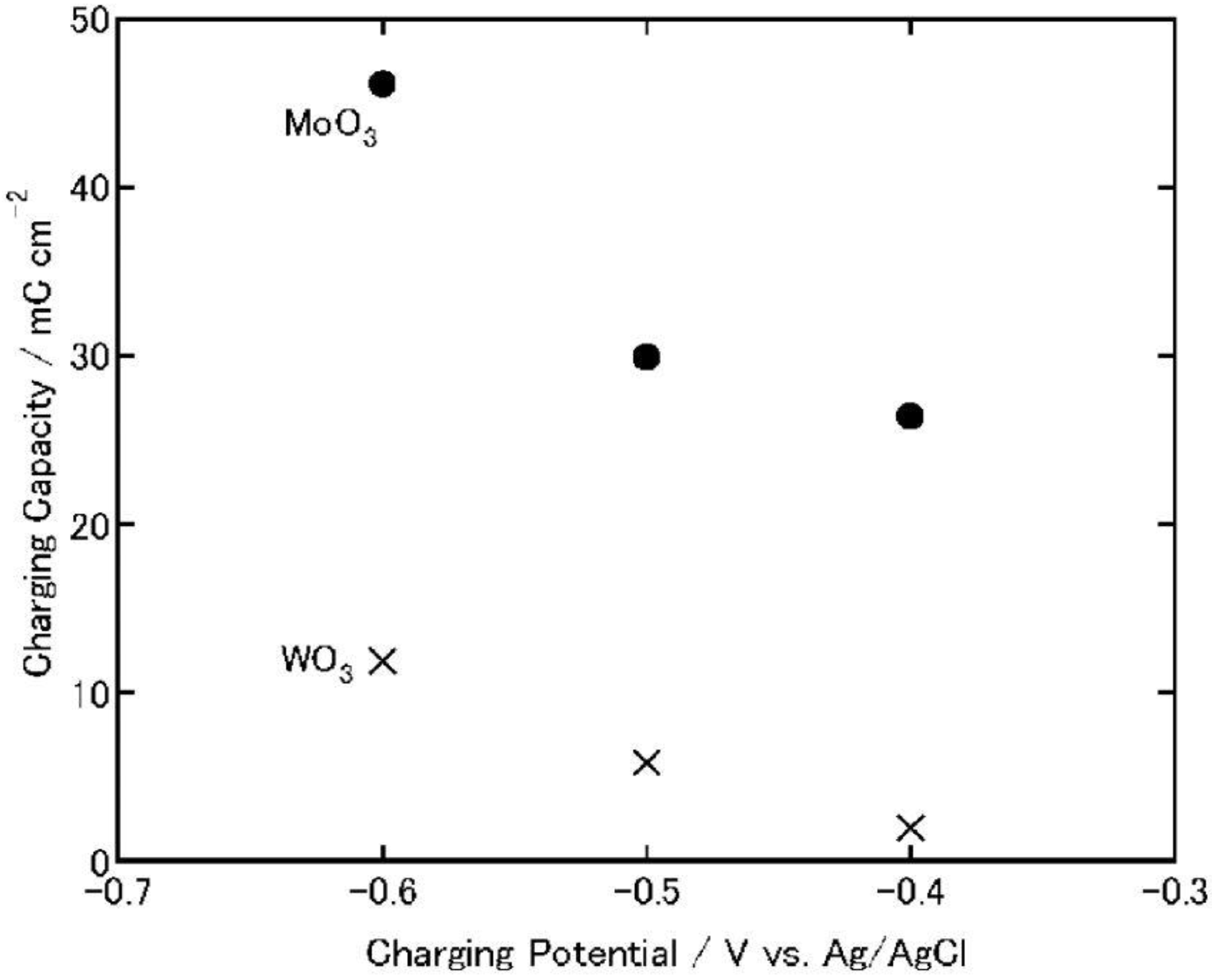
As a comparison, MoO
3 and WO
3 films were electrochemically charged at −0.4, −0.5 or −0.6 V versus Ag|AgCl for 1 h, and discharged at 1 μA (cut-off potential = −0.1 V;
Figure 7 and
Figure 8). As the charging potential was shifted more negatively, both the charging and discharging capacities of WO
3 increased.
Figure 7.
Charging capacities of MoO
3 and WO
3 coatings on ITO electrodes when the coatings are charged electrochemically (1 h) in 3 wt. % NaCl aqueous solutions (pH 5) [
23]. Reproduced with permission from Elsevier, © 2004.
Figure 7.
Charging capacities of MoO
3 and WO
3 coatings on ITO electrodes when the coatings are charged electrochemically (1 h) in 3 wt. % NaCl aqueous solutions (pH 5) [
23]. Reproduced with permission from Elsevier, © 2004.
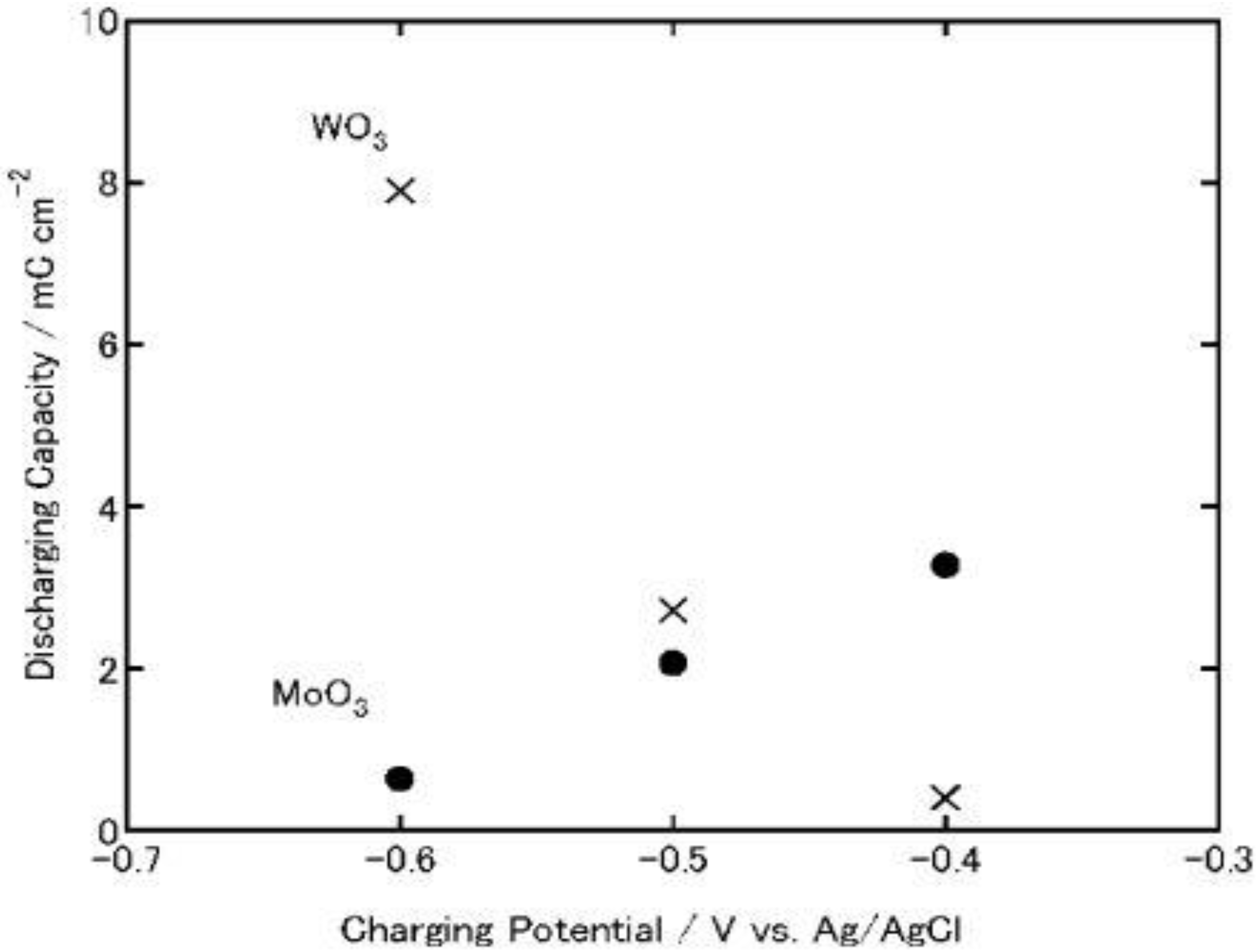
On the other hand, in the case of MoO3, its discharging capacity decreased while its charging capacity increased. The discharging efficiency (discharging capacity/charging capacity) of WO3 increased constantly as the charging potential was shifted negatively (0.23, 0.46 and 0.66 at −0.4, −0.5 and −0.6 V, respectively). However, that of MoO3 decreased (0.12, 0.076 and 0.014 at −0.4, −0.5 and −0.6 V. respectively). After the discharging, the color of the WO3 was almost the same as that before charging while that of the MoO3 film was slightly blue, indicating that the film was still partially reduced. Thus, the low discharging efficiency of MoO3 may be explained in terms of slow reoxidation or high electrical resistance of MxMoO3. In addition, at more negative potentials, MoO3 might be partially reduced to irreversibly intercalated state or to metallic state, which cannot be reoxidized easily to the initial state. Moreover, the fast reoxidation of MoO3 by dissolved oxygen during the electrochemical charging may be responsible for the low efficiency.
Figure 8.
Discharging capacities of MoO
3 and WO
3 coatings on ITO electrodes. The coatings were discharged electrochemically at 1μA (cut-off potential = −0.1V vs. Ag|AgCl) after electrochemical charging (
Figure 3) in 3 wt. % NaCl aqueous solution (pH 5) [
23]. Reproduced with permission from Elsevier, © 2004.
In either event, when the charging potential is −0.4 V, which is the photopotential of TiO2, the charging and discharging capacities of MoO3 are one order of magnitude larger than those of WO3. Therefore, MoO3 could be used as an energy storage material coupled with TiO2.
For a comparison, TiO
2/MoO
3 and TiO
2/WO
3 bilayer films were irradiated with UV light for 8 h in air at relative humidity of 80%, and then its open-circuit potential was monitored in a 3 wt. % NaCl aqueous solution, respectively. As a result, the self-discharging time of TiO
2/MoO
3 bilayer film was elongated to >1.5 h (
Figure 8). However, the TiO
2/WO
3 bilayer film charged under the same conditions exhibited longer self-discharging time than TiO
2/MoO
3 film. Thus, TiO
2/MoO
3 composite film should be more suitable to be used as energy storage materials in air under humid conditions if the MoO
3 overlayer is sufficiently thin and the film retains enough adsorbed water on the surface.
Although WO3 has a longer self-discharging time than MoO3, MoO3 exhibited larger charging and discharging capacities and greater ability for oxygen reduction than WO3. TiO2/MoO3 composite film can also be charged photoelectrochemically in an electrolyte or humid air. Therefore, TiO2/MoO3 composites may function as energy storage materials under humid conditions.
However, TiO
2 photocatalyst has some limitations, which come from its own electronic structure. It can work only under UV illumination (wavelength < 380 nm). To overcome the limitation, visible-light responsive Au–TiO
2 photocatalyst have been developed [
35].
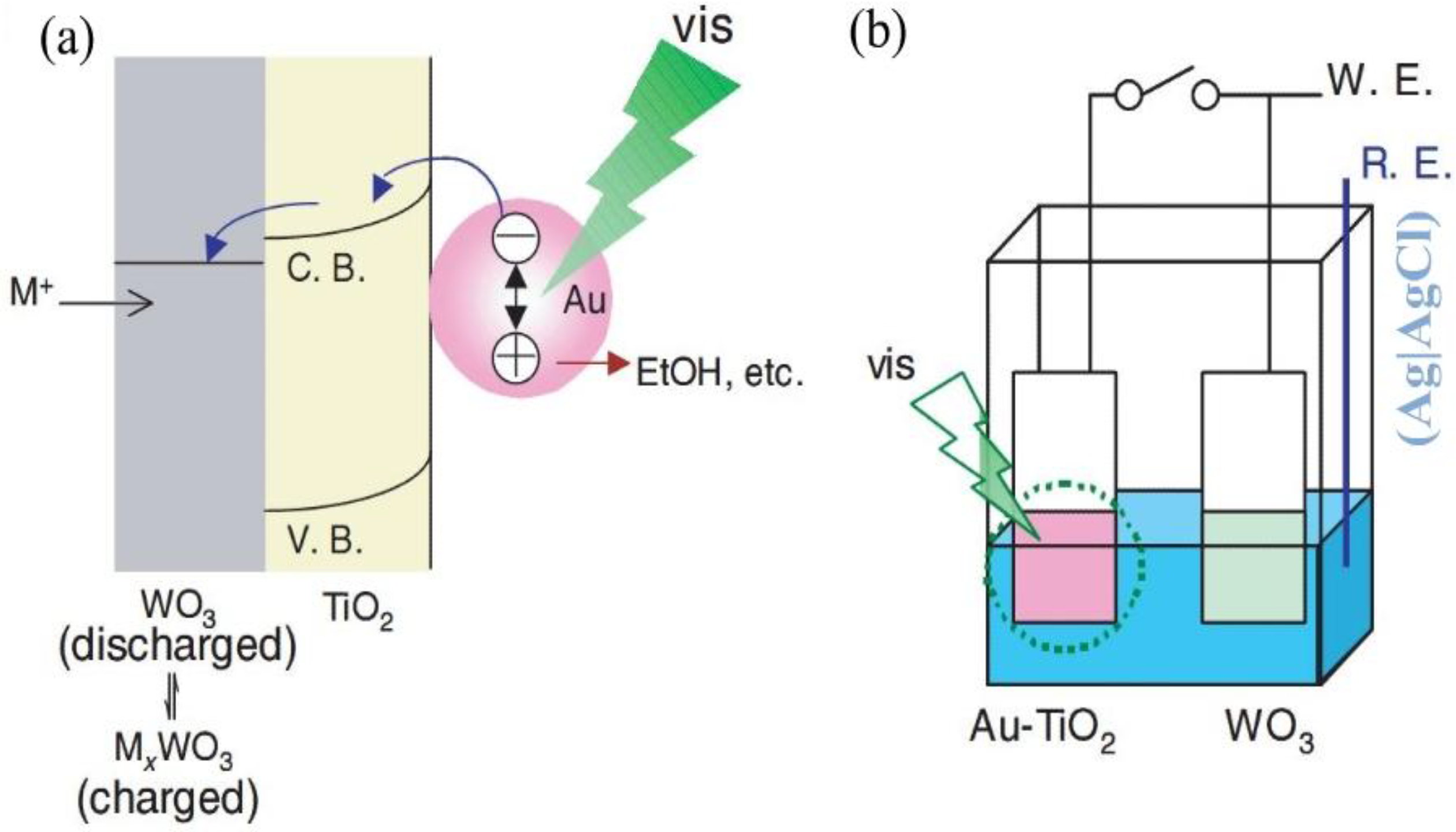
Figure 9a shows the model for visible-light responsive materials with reductive energy storage abilities. The photopotential of the TiO
2-coated electrode without Au nanoparticles was ~0.0 V under visible light. The open-circuit potential of the Au-TiO
2-coated electrode was ~+0.1 V vs. Ag|AgCl in the electrolyte, and the potential shifted to ~0.2 V under visible light (> 480 nm; ~600 mW cm
−2). When the Au-TiO
2 film is irradiated, some of the Au nanoparticles are excited by localized surface plasmon resonance (LSPR) and electrons are transferred to TiO
2. When there is an energy storage material (WO
3, MoO
3, and PWA) combined with the Au-TiO
2 film, the reductive energy will be stored. On the other hand, the positive charges left on the Au nanoparticles are consumed by the oxidation of ethanol in the electrolyte, probably to acetic acid.
Figure 9.
(a) A model for visible-light responsive materials with reductive energy storage abilities. (b) Experimental setup for reductive energy storage in a WO
3 film by a visible-light irradiated Au-TiO
2 film [
35]. Reproduced with permission from Elsevier, © 2008.
Figure 9.
(a) A model for visible-light responsive materials with reductive energy storage abilities. (b) Experimental setup for reductive energy storage in a WO
3 film by a visible-light irradiated Au-TiO
2 film [
35]. Reproduced with permission from Elsevier, © 2008.

 TiO2 * (e− + h+)
 HxWO3
HxWO3


 MxWO3
MxWO3

